VB
VB
2
VB Series Offers High Sealability and
Long Life with Aluminum Die-cast
Enclosure
s
Ideal for machine tools and sequential
control
s
Switch box has an oil drain
s
Sturdy construction through integration
of head with body
s
Ground terminal models have EN/IEC
approval (CE marking)
Ordering Information
Multiple Plunger Limit Switch
VB
s
LIMIT SWITCHES
Actuator
Conduit
With flange (by no. of actuators)
Without flange (by no. of actuators)
type
2
3
4
5
6
2
3
4
5
6
G1/2
VB-2211
VB-3211
VB-4211
VB-5211
VB-6211
VB-2241
VB-3241
VB-4241
VB-5241
VB-6241
2 cond.
G1/2
VB-2221
VB-3221
VB-4221
VB-5221
VB-6221
VB-2251
VB-3251
VB-4251
VB-5251
VB-6251
4 cond.
G1/2
VB-2111
VB-3111
VB-4111
VB-5111
VB-6111
VB-2141
VB-3141
VB-4141
VB-5141
VB-6141
2 cond.
G1/2
VB-2121
VB-3121
VB-4121
VB-5121
VB-6121
VB-2151
VB-3151
VB-4151
VB-5151
VB-6151
4 cond.
s
ACCESSORIES
Item
Part number
Built-in switch for replacement (standard type)
VB-S101N
Built-in switch for replacement (micro load type)
VB-S109N
Cable dia. range: 5.5 to 7.5 mm
SC-1M
Cable dia. range: 7.5 to 9.5 mm
SC-2M
Cable dia. range: 11 to 13 mm
SC-3M
Cable dia. range: 9 mm to 11 mm
SC-5M
Note:
1. Micro load (0.1 A) types are available. To order, add an "A" after the part number.
(ex.: VB-2211
VB-2211A)
2. Ground terminal types are available. To order, add an "E" after the part number.
(ex.: VB-2211
VB-2211E)
3. No replacement parts for actuators.
Roller
plunger
Bevel
plunger
Metal cable fitting with sealing washer
for G1/2 conduit

VB
VB
3
1
Specifications
s
RATINGS
s
MODEL NUMBER LEGEND
Base Units
VB -
1. Number of actuators
2: 2 actuators
3: 3 actuators
4: 4 actuators
5: 5 actuators
6: 6 actuators
2. Actuator
1: Bevel plunger
2: Roller plunger
3. Switch box
1: 2 conduits with flange
2: 4 conduits with flange
4: 2 conduits without flange
5: 4 conduits without flange
4. Rubber material (scraper)
1: NBR (Nitrite Butadiene rubber)
2: FPM (Fluorine rubber)
5. Contacts rating
None: 10 A (standard)
A:
0.1 A
6. Special type
None: Without a ground terminal
E:
With a ground terminal
Construction
Standard
Micro load
Rated voltage
Resistive load (A)
NC
NO
125 VAC
10
250 VAC
125 VDC
0.5
250 VDC
0.25
Rated voltage
Resistive load (A)
125 VAC
0.1
8 VDC
30 VDC
Inrush current
NC
NO
36 A max
24 A max
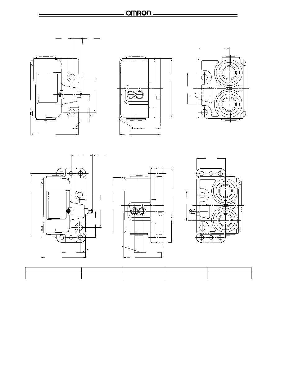
Internal actuator
Cap
Sealing cap
Switch box
Plunger
Seal scraper
Cap screw
O-ring
Built-in switch
Gasket
Cover
2 3 4 5 6
VB
VB
4
Enclosure rating
IP67
Life expectancy
Mechanical
5,000,000 operations min.
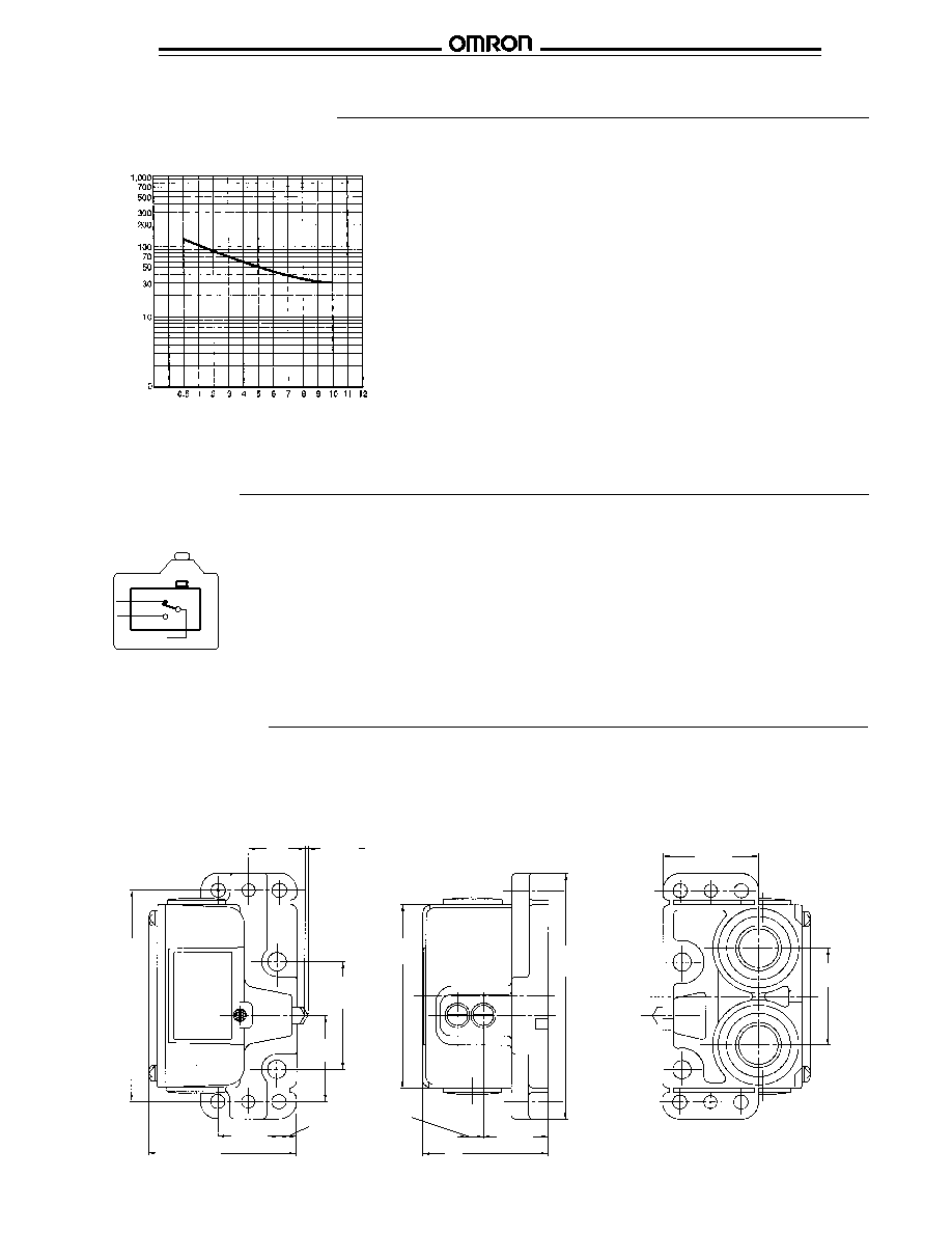
Electrical
300,000 operations min. (at 250 VAC 10 A resistive load)
Operating speed
0.1 mm/s to 0.5 m/s (0.039 to 19.69 in/sec)
Operating frequency
Mechanical
120 operations per minute max.
Electrical
30 operations per minute max.
Rated frequency
50/60 Hz
Insulation resistance
100 M
min. (at 500 VDC)
Contact resistance
10 m
max. (initial value)
Dielectric strength
1,000 VAC min.: between terminals of same polarity
1,500 VAC min.: between current-carrying metal part and ground
1,500 VAC min.: between each terminal and non-current-carrying
metal part
Rated impulse voltage (U
imp
)
4 kV (EN60947-5-1): between current-carrying metal part and
ground
4 kV (EN60947-5-1): between each terminal and non-current-
carrying metal part
4 kV (EN60947-5-1): between terminals of different polarity
Rated insulaton voltage (U
i
)
300 V (EN60947-5-1)
Switching overvoltage
1,000 V max (EN60947-5-1)
Pollution degree (operating environment)
3 (EN60947-5-1)
Short-circuit protective device
10 A fuse, type gl or gG (IEC 269)
Conditional short-circuit current
100 A (EN60947-5-1)
Conventional enclosed thermal current (I
the
)
5 A, 0.5 A (EN60947-5-1)
Protection against electric shock
Class I
Vibration resistance
Malfunction
10 to 55 Hz 1.5 mm (0.06 in.) double amplitude
Shock resistance
Destruction
1,000 m/s
2
min. (approx. 100 G min.) (3280 ft/s
2
)
Malfunction
200 m/s
2
min. (approx. 20 G min.) (656 ft/s
2
)
Ambient temperature
-10
∞
C to 80
∞
C (14
∞
F to 176
∞
F) (no icing)
Ambient humidity
95% RH max.
Weight
Approx. 580 g (VB-4211) (20.5 oz)
s
APPROVED STANDARD RATINGS
TUV (EN60947-5-1)
Standard
Micro load
Utilization category
AC-15
DC-12
AC-14
DC-12
Rated operating current (l
e
)
2 A
0.1 A
Rated operating voltage (U
e
)
250 V
48 V
125 V
30 V
s
CHARACTERISTICS
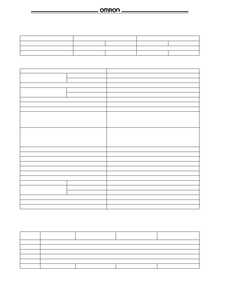
Model
VB- 221
VB- 251
VB- 121
VB- 151
VB- 211
VB- 241
VB- 111
VB- 141
OF max
14.71 N (1500 gf) (3.31 lbf)
RF max
4.90 N (500 gf) (1.11 lbf)
PT max
1.5 mm
OT min
3.5 mm
MD
0.5 mm
OP
32
±
0.4 mm
19
±
0.4 mm
26
±
0.4 mm
13
±
0.4 mm
s
OPERATING CHARACTERISTICS
Note:
The above mechanical and electrical life is ensured at an ambient temperature of 5
∞
C to 35
∞
C and an ambient humidity of 40%
to 70%.
..