 | –≠–ª–µ–∫—Ç—Ä–æ–Ω–Ω—ã–π –∫–æ–º–ø–æ–Ω–µ–Ω—Ç: WLRCA2-TS | –°–∫–∞—á–∞—Ç—å:  PDF PDF  ZIP ZIP |
Document Outline
- Front Page
- Ordering Information
- Construction
- Specifications
- Engineering Data
- Operation
- Dimensions
- Installation
- Overtravel Type
- High-Precision Type
- Contacting Omron
WL
WL
2
Fork
lock
lever
Roller
lever
Ordering Information
s
BASIC TYPE SIDE ROTARY SWITCHES
Actuator
Part number
Complete
Head with
Lever
Head
Built-in switch
Leverless
switch
lever
Short (38 mm radius)
WLCA2-TS
WL-1H1100
WL-1A100
WL-1H
W-10FB3
WLRCA2-TS
Medium (50 mm radius)
WLCA2-7TS
WL-1H1200
WL-1A200
Long (63 mm radius)
WLCA2-8TS
WL-1H1300
WL-1A300
Adjustable roller lever
WLCA12-TS
WL-1H2100
WL-2A100
Adjustable rod lever (140 mm)
WLCL-TS
WL-4H4100
WL-4A100
WL-4H
WLRCL-TS
Left roller on front,
WLCA32-41TS
WL-5H5100
WL-5A100
WL-5H
WLRCA32-TS
right roller on back
Left roller on back,
WLCA32-42TS
WL-5H5102
WL-5A102
right roller on front
Both rollers on front
WLCA32-43TS
WL-5H5104
WL-5A104
s
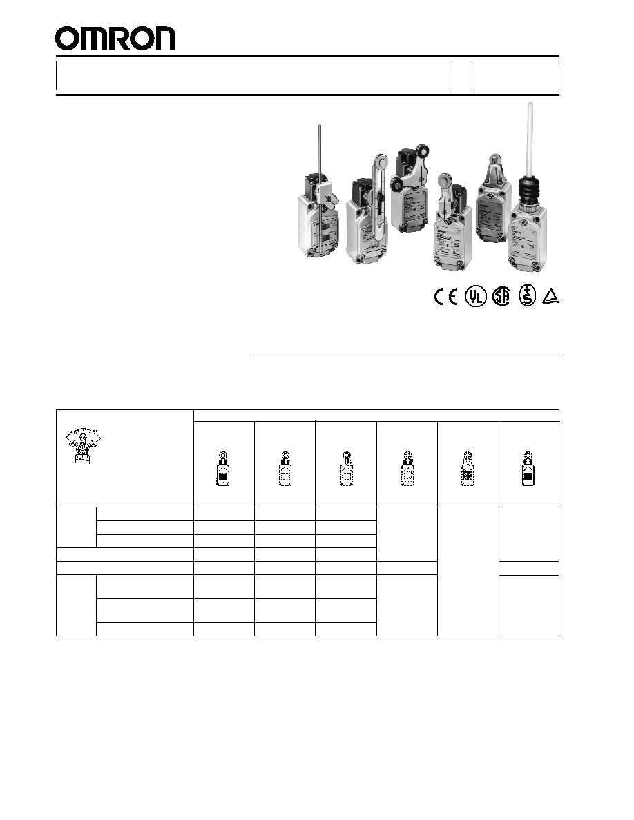
Rugged diecast housing
s
High mechanical strength
s
Oiltight, waterproof, dustproof
construction
s
Overtravel and high-precision types
available
s
Choose switches with neon lamp or
LED status indicator
Wide Selection of Two-Circuit
Double-Break Limit Switches
Robust General-Purpose Limit Switch
WL
Total travel 45 degrees, with one-way operation option, 1/2-14NPT conduit (-TS type)

WL
WL
3
Adj. rod
lever
Adj. roller
lever
s
OVERTRAVEL TYPE SIDE ROTARY SWITCHES
Actuator
Part number
Complete
Head with
Lever
Head
Built-in switch
Leverless
switch
lever
Roller
Short (38 mm radius),
WLH2-TS
WL-2H1100
WL-1A100
WL-2H
W-10FB3
WLRH2-TS
lever
standard sensitivity
Short, high sensitivity
WLG2-TS
W-10FB3-8
WLRG2-TS
Standard sensitivity
WLH12-TS
WL-2H2100
WL-2A100
W-10FB3
WLRH2-TS
High sensitivity
WLG12-TS
W-10FB3-8
WLRG2-TS
140 mm, std. sensitivity
WLHL-TS
WL-2H4100
WL-4A100
W-10FB3
WLRH2-TS
140 mm, high sensitivity
WLGL-TS
W-10FB3-8
WLRG2-TS
380 mm, std. sensitivity
WLHAL4-TS
WL-2H3100
WL-3A100
W-10FB3
WLRH2-TS
Spring rod lever
WLHAL5-TS
WL-2H3200
WL-3A200
Total travel 80 degrees, without one-way operation option, 1/2-14NPT conduit (-TS type)
s
OVERTRAVEL TYPE SIDE ROTARY SWITCHES
Actuator
Part number
Complete
Head with
Lever
Head
Built-in switch
Leverless
switch
lever
Roller
Short (38 mm radius)
WLCA2-2NTS WL-6H1100
WL-1A100
WL-6H
W-10FB3
WLRCA2-
lever
2NTS
Adj. roller lever
WLCA12-
WL-6H2100
WL-2A100
WLRCA12-
2NTS
2NTS
Adj. rod lever, 140 mm
WLCL-2NTS
WL-6H3100
WL-3A100
WLRCAL4-
2NTS
Total travel 90 degrees, with one-way operation option (-2N type), 1/2-14NPT conduit (-TS type)
Roller
lever
s
HIGH PRECISION TYPE SIDE ROTARY SWITCHES
Actuator
Part number
Complete
Head with
Lever
Head
Built-in switch
Leverless
switch
lever
Short (38 mm radius)
WLGCA2-TS
WL-1H1100-1
WL-1A100
N/A
W-10FB3-4
WLRGCA2-TS
Medium (50 mm radius)
WLGCA2-7TS WL-1H1200-1
WL-1A200
Long (63 mm radius)
WLGCA2-8TS WL-1H1300-1
WL-1A300
Adjustable roller lever
WLGCA12-TS WL-1H2100-1
WL-2A100
Adjustable rod lever (140 mm)
WLGCL-TS
WL-4H4100-1
WL-4A100
WLRGCL-TS
Total travel 45 degrees, with one-way operation option, 1/2-14NPT conduit (-TS type)
WL
WL
4
s
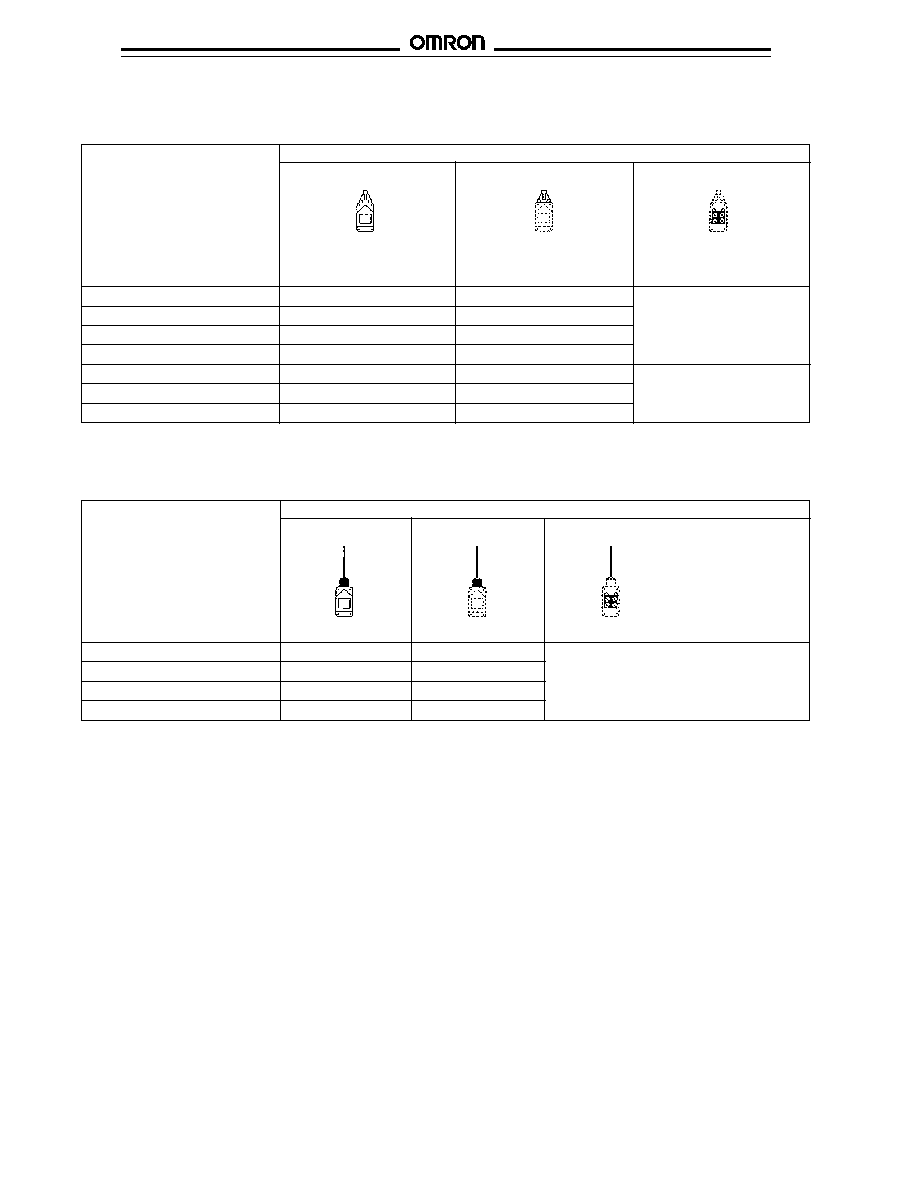
PLUNGER SWITCHES
Actuator
Part number
Complete switch
Head with actuator
Built-in switch
Top plunger
WLD-TS
WL-7H100
W-10FB3
Top roller plunger
WLD2-TS
WL-7H200
Top sealed roller plunger
WLD28-TS
WL-7H400
Top ball plunger
WLD3-TS
WL-7H300
Horizontal plunger
WLSD-TS
WL-8H100
W-10FB3-4
Horizontal roller plunger
WLSD2-TS
WL-8H200
Horizontal ball plunger
WLSD3-TS
WL-8H300
1/2-14NPT conduit (-TS type)
s
COIL SPRING / STEEL WIRE SWITCHES
Actuator
Part number
Complete switch
Head with actuator
Built-in switch
Coil spring, 6.5 mm dia.
WNJ-TS
WL-9H100
W-10FB3
Coil spring, 5.0 mm dia.
WLNJ30-TS
WL-9H200
Steel wire, 1.0 mm dia.
WLNJ-S2TS
WL-9H400
Nylon rod, 8.0 mm dia.
WLNJ-2TS
WL-9H300
1/2-14NPT conduit (-TS type)
s
STATUS INDICATOR EQUIPPED SWITCHES
Any of the WL switches above can be ordered with a neon or LED indicator that shows normally open and normally closed status. For a
neon indicator, add "-LE" to the end of a part number, for example, WLD2-TSLE. For an LED indicator, add "-LD" to the end of a part
number, for example, WLCA2-TSLD.

WL
WL
5
s
MODEL NUMBER LEGEND
Base Units
WL -
≠
1
Identifier
Symbol
Definition
1
Electrical ratings
None
10A, 125/250/480 VAC Rivet
01
0.1 A, 125/250 VAC Micro current/voltage crossbar
2
Head, actuator
--
See following "Head and Actuator Chart"
3
Corrosion
None
Non-corrosion-proof or acid-proof
RP
Corrosion-proof type
P1
Acid-proof type
4
Built-in switch
None
W-10FB3 (standard type)
55
W-10FB3-55 (special hermetic type)
5
Operating temp.
None
-10
∞
C to 80
∞
C
TH
5
∞
C to 120
∞
C (high temp. type)
TC
-40
∞
C to 40
∞
C (low temp. type)
6
Special hermetic
None
Without cable/no part is molded/standard switch (W-10FB3)
136
With 5M VCI cable pre-wired/conduit opening is resin-molded/standard built-in switch
(W-10FB3)
139
With 5M VCI cable pre-wired/conduit opening and case cover are resin-molded/standard
built-in switch (W-10FB3)
140
With 5M VCI cable pre-wired/special hermetic built-in switch (W-10FB3-55)
141
With 5M VCI cable pre-wired/conduit opening and case cover are resin-molded/special
hermetic built-in switch (W-10FB3-55)
RP40
With 5M S-flex cable pre-wired/conduit opening and case cover are resin-molded/special
hermetic built-in switch (W-10FB3-55)/special molding head
RP60
With 5M S-flex cable pre-wired/conduit opening and case cover are resin-molded/special
hermetic built-in switch (W-10FB3-55)/viton sealed
7
Conduit
None
PF
1
/
2
without Earth Terminal
G1
PF
1
/
2
with Earth Terminal
G
PG 13.5 with Earth Terminal
Y
M20 with Earth Terminal
TS
1
/
2
-14NPT with Earth Terminal
8
Operating indicator
None
Without indicator
LE
With neon indicator (125 to 250 VAC)
LD
With LED indicator (10 to 115 VAC/VDC)
9
Lever clamping
None
With single nuts
A
With double nuts
10
Spatter proof option
None
Non-spatter-proof type
S
Spatter-proof type
11
Pre-wired connector/
None
Screw terminal
receptacle option
K13
4-pin receptacle (NO, DC type, wired no.3 & no.4)
K13A
4-pin receptacle (NO, AC type, wired no.3 & no.4)
K43
4-pin receptacle (DC type, all wired)
K43A
4-pin receptacle (AC type, all wired)
-M1J
Pre-wired connector (4-pin, NO, DC type, wired no.3 & no.4, 0.3m cable)
-AGJ03
Pre-wired connector (4-pin, AC type, 0.3m cable)
-DGJ03
Pre-wired connector (4-pin, DC type, 0.3m cable)
2
3 4 5 6 7 8 9 10 11

WL
WL
6
Head and Actuator Chart
Symbol
Definition
CA2
Roller lever, short (38 mm radius), with one-way operation option
CA2-7
Roller lever, medium (50 mm radius), with one-way operation option
CA2-8
Roller lever, long (63 mm radius), with one-way operation option
H2
Roller lever, short (38 mm radius), overtravel: 80 degrees
G2
Roller lever, short (38 mm radius), overtravel: 80 degrees, high sensitivity
CA2-2
Roller lever, short (38 mm radius), overtravel: 90 degrees
CA2-2N
Roller lever, short (38 mm radius), overtravel: 90 degrees, with one-way operation option
GCA2
Roller lever, short (38 mm radius), high precision, with one-way operation option
GCA2-7
Roller lever, medium (50 mm radius), high precision, with one-way operation option
GCA2-8
Roller lever, long (63 mm radius), high precision, with one-way operation option
CA12
Adjustable roller lever, with one-way operation option
H12
Adjustable roller lever, overtravel: 80 degrees
G12
Adjustable roller lever, overtravel: 80 degrees, high sensitivity
CA12-2
Adjustable roller lever, overtravel: 90 degrees
CA12-2N
Adjustable roller lever, overtravel: 90 degrees, with one-way operation option
GCA12
Adjustable roller lever, high precision
CL
Adjustable rod lever (140 mm), with one-way operation option
HL
Adjustable rod lever (140 mm), overtravel: 80 degrees
HLAL4
Adjustable rod lever (380 mm), overtravel: 80 degrees
GL
Adjustable rod lever (140 mm), overtravel: 80 degrees, high sensitivity
CL-2N
Adjustable rod lever (140 mm), overtravel: 90 degrees, with one-way operation option
HAL5
Spring rod lever, overtravel: 80 degrees
CA32-41
Fork lock lever, left roller on front, right roller on back, with one-way operation option
CA32-42
Fork lock lever, left roller on back, right roller on front, with one-way operation option
CA32-43
Fork lock lever, both rollers on front, with one-way operation option
D
Top plunger
D2
Top roller plunger
D28
Top sealed roller plunger
D3
Top ball plunger
SD
Horizontal plunger
SD2
Horizontal roller plunger
SD3
Horizontal ball plunger
NJ
Coil spring, 6.5 mm dia.
NJ-30
Coil spring, 5.0 mm dia.
NJ-2
Nylon rod, 8.0 mm dia.
NJ-2S
Steel wire, 1.0 mm dia.

WL
WL
7
Rated
voltage
Non-inductive load
Inductive load
Resistive load
Lamp load
Inductive load
Motor load
NC
NO
NC
NO
NC
NO
NC
NO
125 VAC
10 A
10 A
3 A
1.5A
10 A
5 A
2.5 A
250 VAC
10 A
10 A
2 A
1 A
10 A
3 A
1.5 A
480 VAC
10 A
10 A
1.5 A
0.8 A
3 A
1.5 A
0.8 A
600 VAC
3 A
1 A
1 A
0.5 A
1.5 A
1 A
0.5 A
8 VDC
10 A
6 A
3 A
10 A
6 A
14 VDC
10 A
6 A
3 A
10 A
6 A
30 VDC
6 A
4 A
3 A
6 A
4 A
125 VDC
0.8 A
0.2 A
0.8 A
0.2 A
250 VDC
0.4 A
0.1 A
0.4 A
0.1 A
Microvoltage/Current Load Model (WL01 )
Note:
1. Inductive loads have a power factor of 0.4 min. (AC) and a time constant of 7 ms max. (DC).
2. Lamp load has an inrush current of 10 times the steady-state current.
3. Motor load has an inrush current of 6 times the steady-state current.
Construction
Too much Overtravel, adjustment needed.
Too much Overtravel, adjustment needed.
Too little Overtravel, adjustment needed.
Normal operation
Normal operation
Operating Head
Roller lever, rod lever and side
plunger types may be locked in
at any of four 90
∞
positions.
Proper Operation Zone Markers
Two raised markers on the shaft
housing indicate the proper limits
for normal operation to simplify
installation.
Axis Bearing
Assures smooth plunger movement.
Shaft Seal
O-ring provides a high
degree of sealing.
Built-in Switch
Long mechanical life of 15
million operations, minimum.
Conduit Entrance
1/2-14 NPT
Roller
Sintered stainless steel with self-
lubricating bearing resists wear.
Lever
Aluminum alloy resists corrosion.
Roller Lever Mounting Screw
Cover Seal
O-ring provides a high
degree of sealing.
Terminal Screws
Four M4 screws
Insulation
Material provides insulation and
seals out corrosive gas.
Cover Mounting Screws
Self-retaining Phillips head
screws will not fall out.
Specifications
s
GENERAL RATINGS
Rated voltage
Resistive Load
125 VAC
0.1 A
30 VDC
WL
WL
8
s
EN60947-5-1 RATINGS
Current (mA)
Voltage (VDC)
Recommended Load Range (DC only)
Zones 1 through 3
Note:
Without neon lamp model
Model
Category and rating
Thermal current (i
the
)
Indicator
WL
AC-15
2 A/250 VAC
10 A
None
DC-12
2 A/48 VDC
WL01
AC-14
0.1 A/125 VAC
0.5 A
None
DC-12
0.1 A/48 VDC
WL -LE
AC-15
2 A/250 VAC
10 A
Neon lamp
WL01 -LE
AC-14
0.1 A/125 VAC
0.5 A
Neon lamp
WL -LD
AC-15
2 A/115 VAC
10 A
LED
DC-12
2 A/48 VDC
WL01 -LD
AC-14
0.1 A/115 VAC
0.5 A
LED
DC-12
0.1 A/48 VDC
WL
WL
9
s
APPROVED STANDARDS
Approval
Standard
File no.
UL
UL508
E76675
CSA
CSA C22.2 no. 14
LR45746
TUV
EN60947-5-1
R9551016
SEV
SEV
93.5 51936.01
LR
LR
88/10274 (E3)
s
CHARACTERISTICS
Operating speed
1 mm/s to 2 m/s (with WLCA2)
Operating frequency
Mechanical
120 operations/min.
Electrical
30 operations/min.
Insulation resistance
100 M
min. (at 500 VDC)
Contact resistance
25 m
(initial)
Dielectric strength
1,000 VAC (600 VAC for overtravel model), 50/60 Hz for 1 min
between non-continuous terminals
2,200 VAC, 50/60 for 1 min between each terminal and non-current-
carrying metal part and between each terminal and ground
Rated impulse withstand voltage (U
imp
)
4 kV
Rated insulation voltage (U
i
)
300 VAC (EN60947-5-1)
Thermal current (I
the
)
10 A (0.5 A for micro load type) (EN60947-5-1)
Short-circuit protective device
10 A fuse (type gG, IEC269 approved, EN60947-5-1)
Conditional short circuit current
100 A (EN60947-5-1)
Operating environment pollution degree
3 (EN60947-5-1)
Protection against electric shock
Class I
Temperature rise
50
∞
max
Vibration resistance
Malfunction
10 to 55 Hz, 1.5 mm double amplitude
Shock resistance (See Note 1.)
Destruction
1,000 m/s
2
(approx. 100G)
Malfunction
300 m/s
2
(approx. 30 G)
Ambient temperature
Operating
-10
∞
C to 80
∞
C (14
∞
F to 176
∞
F) with no icing
Ambient humidity
Operating
95% max
Life expectancy
Mechanical
15,000,000 operations min. (See Note 2.)
Electrical
See
Engineering Data
Enclosure ratings
UL
Types 3, 4 and 13
NEMA
Types 1, 2, 3, 3R, 4, 5, 6, 12 and 13
IEC
IP67
Weight
Approx. 275 g (with WLCA2)
Note:
1. Excludes the coil spring models (-NJ)
2. Overtravel model, low differential model, wobble stick model and micro load model: 10,000,000 operations min.
..
WL
WL
10
s
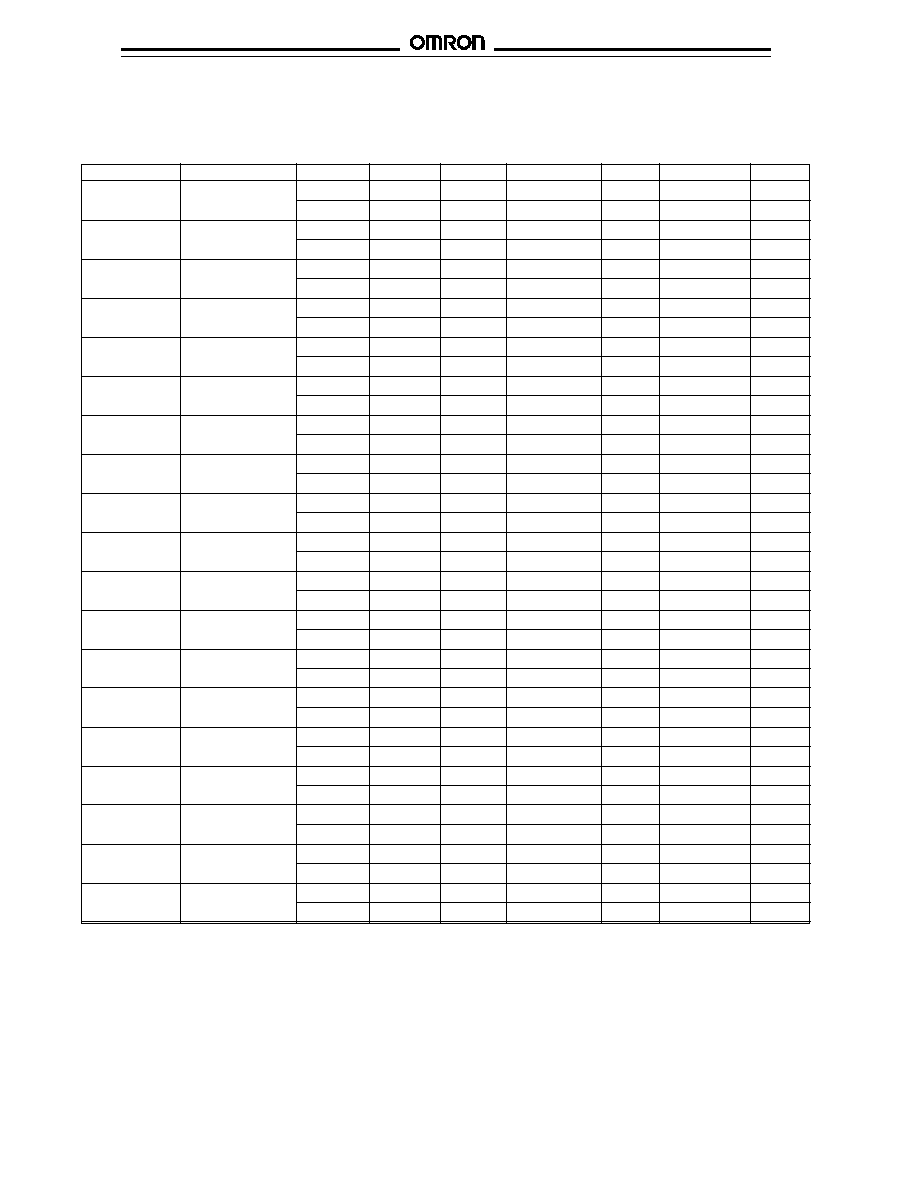
OPERATING CHARACTERISTICS
Legend: OF = Operating Force (max.); RF = Reset Force (min.); OT = Overtravel (min.); PT = Pretravel
MD = Movement Differential (max.); OP = Operating Position; TT = Total Travel (min.); TTP = Total Travel Position (mm/inch)
Note:
* Operating characteristics of WLCA-12-TS is measured at arm length of 38 mm (1.496 in).
** Operating characteristics of WLCL-TS is measured at the rod length of 140 mm (5.512 in)
*** Operating characteristics are measured at the tip of the coil spring or steel wire.
Part number
Description
OF
RF
OT
PT
MD
OP
TT(P)
WLCA2-TS
Short roller lever
1.36 kg
227 g
30
∞
15
∞
±
5
∞
12
∞
--
40
∞
(3 lb)
(8.01 oz.)
WLCA2-7TS
Medium roller lever
1.04 kg
170 g
30
∞
15
∞
±
5
∞
12
∞
--
40
∞
(2.3 lb)
(6.00 oz.)
WLCA2-8TS
Long roller lever
820 g
137 g
30
∞
15
∞
±
5
∞
12
∞
--
40
∞
(28.92 oz.)
(4.83 oz.)
WLCA12-TS*
Adjustable roller
1.36 kg
227 g
30
∞
15
∞
±
5
∞
12
∞
--
40
∞
lever
(3 lb)
(8.01 oz.)
WLCL-TS**
Adjustable rod
142 g
28 g
30
∞
15
∞
±
5
∞
12
∞
--
40
∞
lever
(5.00 oz.)
(0.99 oz.)
WLCA32-41TS
Fork roller lever,
1.2 kg
--
35
∞
50
∞
±
5
∞
--
--
90
∞
±
10
∞
left front, right back
(2.7 lb)
WLCA32-42TS
Fork roller lever,
1.2 kg
--
35
∞
50
∞
±
5
∞
--
--
90
∞
±
10
∞
left back, right front
(2.7 lb)
WLCA32-43TS
Fork roller lever,
1.2 kg
--
35
∞
50
∞
±
5
∞
--
--
90
∞
±
10
∞
both on front
(2.7 lb)
WLD-TS
Plain top plunger
2.72 kg
910 g
6.4 mm
1.7 mm
1 mm
34
±
0.8 mm
29.5 mm
(6 lb)
(2.01 lb)
(0.252 in)
(0.067 in)
(0.04 in)
(1.34
±
0.03 in)
(1.16 in)
WLD2-TS
Top roller plunger
2.72 kg
910 g
5.6 mm
1.7 mm
1 mm
44
±
0.8 mm
39.5 mm
(6 lb)
(2.01 lb)
(0.220 in)
(0.067 in)
(0.04 in)
(1.73
±
0.03 in)
(1.56 in)
WLD28-TS
Top sealed roller
1.7 kg
450 g
5.6 mm
1.7 mm
1 mm
44
±
0.8 mm
39.5 mm
plunger
(3.75 lb)
(15.87 oz.)
(0.220 in)
(0.067 in)
(0.04 in)
(1.73
±
0.03 in)
(1.56 in)
WLD3-TS
Top ball plunger
2.72 kg
910 g
4 mm
1.7 mm
1 mm
44.5
±
0.8 mm
41 mm
(6 lb)
(2.01 lb)
(0.157 in)
(0.067 in)
(0.04 in)
(1.75
±
0.03 in)
(1.61 in)
WLSD-TS
Horizontal plain
4.082 kg
907 g
6.4 mm
2.8 mm
1 mm
40.6
±
0.8 mm
--
plunger
(9.01 lb)
(2.00 lb)
(0.252 in)
(0.110 in)
(0.04 in)
(1.60
±
0.03 in)
WLSD2-TS
Horizontal roller
4.082 kg
907 g
5.6 mm
2.8 mm
1 mm
54.2
±
0.8 mm
--
plunger
(9.01 lb)
(2.00 lb)
(0.220 in)
(0.110 in)
(0.04 in)
(2.13
±
0.03 in)
WLSD3-TS
Horizontal ball
4.082 kg
907 g
4 mm
28 mm
1 mm
54.2
±
0.8 mm
--
plunger
(9.01 lb)
(2.00 lb)
(0.157 in)
(0.110 in)
(0.04 in)
(2.13
±
0.03 in)
WLNJ-TS***
Coil spring,
150 g
--
--
20 mm
±
10 mm
--
--
--
6.5 mm dia.
(5.29 oz.)
(0.79
±
0.39 in)
WLNJ30-TS***
Coil spring,
150 g
--
--
20 mm
±
10 mm
--
--
--
5.0 mm dia.
(5.29 oz.)
(0.79
±
0.39 in)
WLNJ-S2TS***
Steel wire
29 g
--
--
40 mm
±
20 mm
--
--
--
(1.02 oz.)
(1.58
±
0.79 in)
WLNJ-2TS***
Nylon rod
150 g
--
--
40 mm
±
20 mm
--
--
--
(5.29 oz.)
(1.58
±
0.79 in)
WL
WL
11
Engineering Data
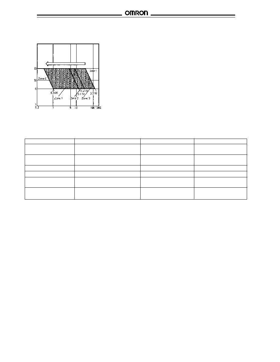
s
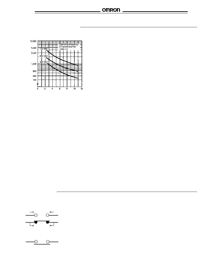
ELECTRICAL LIFE EXPECTANCY
Switching current (mA)
Life expectancy (x 10
3
operations)
Operation
s
CONTACT FORM
Standard/microload models
SPST-NO model
NO
NC
(4)
(3)
NO
NC
(1)
(2)
NO
NO
s
CONTACT RATINGS
NEMA A600 for SPDT switches without status
indicators:
10 A at 125, 250, 480 VAC
1/2 HP at 125 VAC, 1 HP at 250 VAC
0.8 A at 125 VDC, 0.4 A at 250 VDC
0.1 A at 600 VDC
NEMA A300 for SPDT switches with neon status
indicator type
s
CONTACT RESISTANCE
25 m
max (initial)
s
ELECTRICAL APPROVALS
UL Recognized, File No. E76675
CSA Certified, File No. LR45746
WL
WL
12
Actuators for rotary switches such as
WLCA
-TS roller lever and WLCL-TS rod
lever switches can be positioned within a
360
∞
range. Loosen the Allen-head set bolt
on the side of the actuator, position the
actuator, then tighten in place.
Actuator lever
can be installed
at any angle in
360
∞
.
s
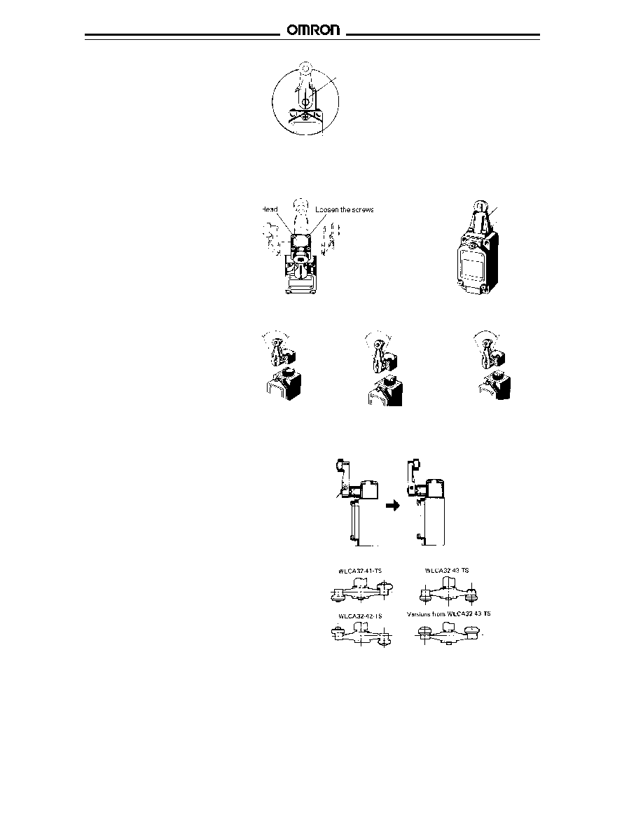
ROTARY ACTUATOR POSITIONING
The operating head of many switches can
be set to four 90
∞
positions to match
installation requirements. Loosen the four
Phillips head screws on the operating
head, and lift the head off. Then, position
with the shaft in the desired direction.
Replace the four screws to fasten the
operating head. Applicable switches
include those with roller levers (WLCA
-
TS), rod levers (WLCL-TS), horizontal
plungers (WLSD
-TS) and roller plungers
(WLD2-TS and WLD28-TS).
s
OPERATING HEAD POSITIONING
Example of roller lever, rod lever and
horizontal plunger switches
Head
Loosen the screws
Example of roller plunger switches
Rotary actuator switches can be set for
clockwise (CW), counterclockwise (CCW) or
operation both ways (CW+CCW). To change
the operating direction, loosen the four
screws on the switch head. Then, lift off the
head. The plunger marker inside is set
parallel with the face plate, as shown at right.
Turn the plunger so the marking faces left for
CW or right for CCW as shown. Replace the
actuator head in the direction suitable for the
installation and tighten the four screws.
s
OPERATING DIRECTION OF STANDARD SWITCHES
Operates
CCW
90
∞
operation
to left
CW+CCW
(both ways
operation)
Operates
Operates
CW
90
∞
operation
to right
Operates
s
ROLLER LEVER ACTUATOR POSITIONING
The roller(s) on roller lever actuators may
be faced inward toward the operating head
or use the more typical installation with the
roller lever facing away from the body. To
change the actuator position, loosen the
Allen-head set bolt, pull the actuator off,
and reposition it on the shaft. Then, tighten
the set bolt at the desired angle.
Loosen the
Allen-head
set bolt
s
FORK ROLLER LEVER ACTUATORS
The illustration at right indicates the
differences among the fork lever actuators.
All may be reversed as shown above.

WL
WL
13
s
STATUS INDICATOR EQUIPPED SWITCH OPERATION
WL switches are available with neon lamp
(WL
-TS-LE) or LED (WL
-TS-
LD) status indicators for easy monitoring
and troubleshooting. They come factory-
set for Normally Open operation ON. It is
easy to change the status to Normally
Closed operation ON. See the Installation
section for details.
Part number
Indicator type
Rated voltage
Leakage current
WL
-TS-LE
Neon lamp
125 VAC
Approx. 0.6 mA
250 VAC
Approx. 1.9 mA
WL
-TS-LD
LED
10 to 115 VAC
Approx. 1 mA
10 to 115 VDC
Factory
installed
position
for
Normally
Open ON
Indicator lights
when NC contacts
release (when
actuator rotates or
is pushed down)
Indicator is lit
while actuator is
free, then goes off
when NO contacts
close: when
actuator rotates or
is pushed down
When connecting a limit switch to a
programmable controller, select the neon
lamp or LED with the smallest leakage
current. Refer to the table at right.
To change operation to Normally Closed
ON, remove the cover from the switch
body, and rotate lamp holder 180
∞
. Then,
replace the unit in the housing.
Switches with adjustable lever and rod
actuators can be set to desired length by
loosening the Allen-head set screw, setting
the length. Then tighten the set screw.
Rod lever switch
Adjustable roller lever switch
s
ADJUSTING LEVER AND ROD LENGTH
WL
WL
14
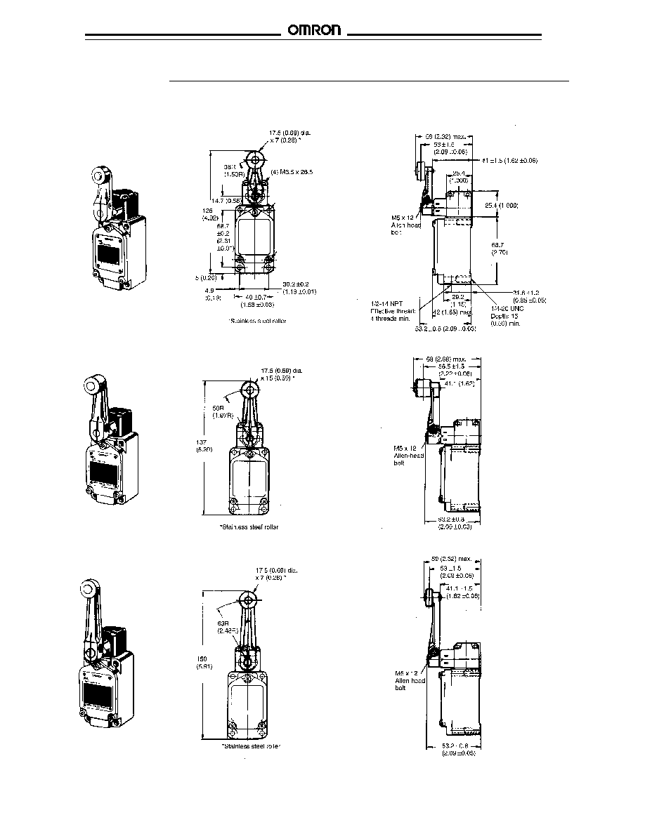
s
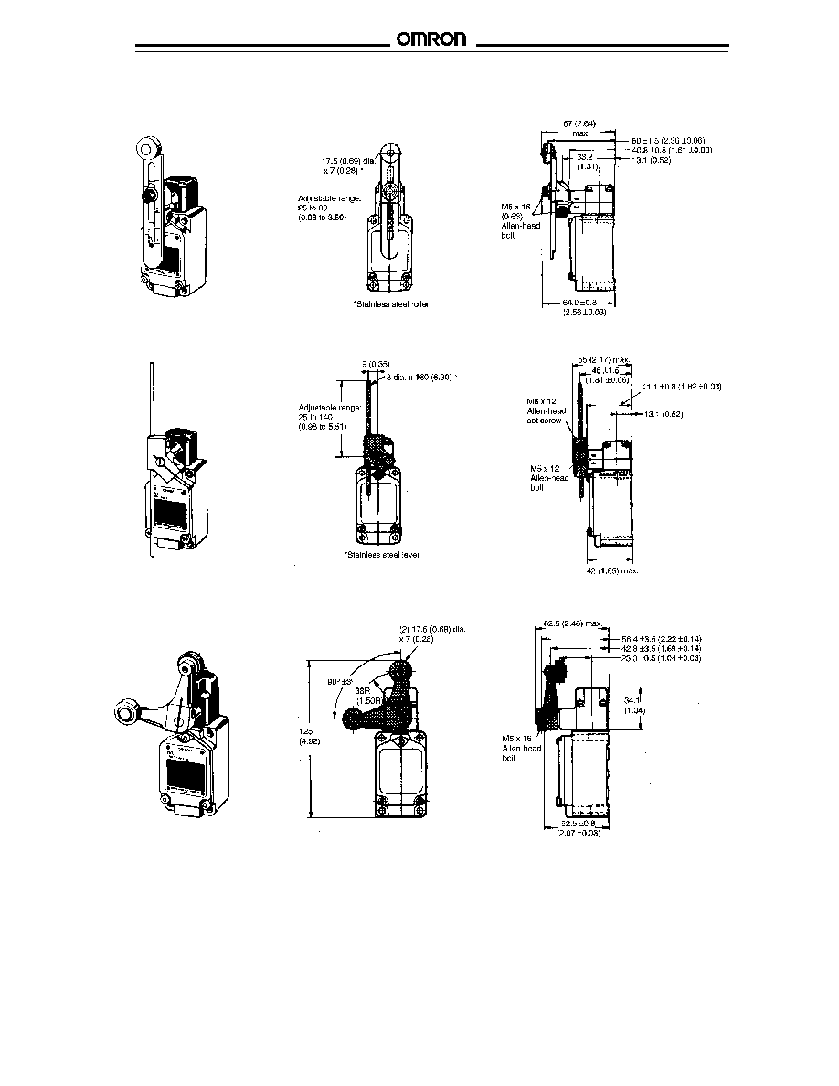
LIMIT SWITCHES
Unit: mm (inch)
WLCA2-TS Short Roller Lever Switch
WLCA2-7TS Medium Roller Lever Switch
Dimensions
WLCA2-8TS Long Roller Lever Switch
WL
WL
15
WLCA32-41, WLCA32-42, WLCA32-43 Fork Roller Lever Switches
Unit: mm (inch)
WLCL-TS Adjustable Rod Lever Switch
WLCA12-TS Adjustable Roller Lever Switch
WL
WL
16
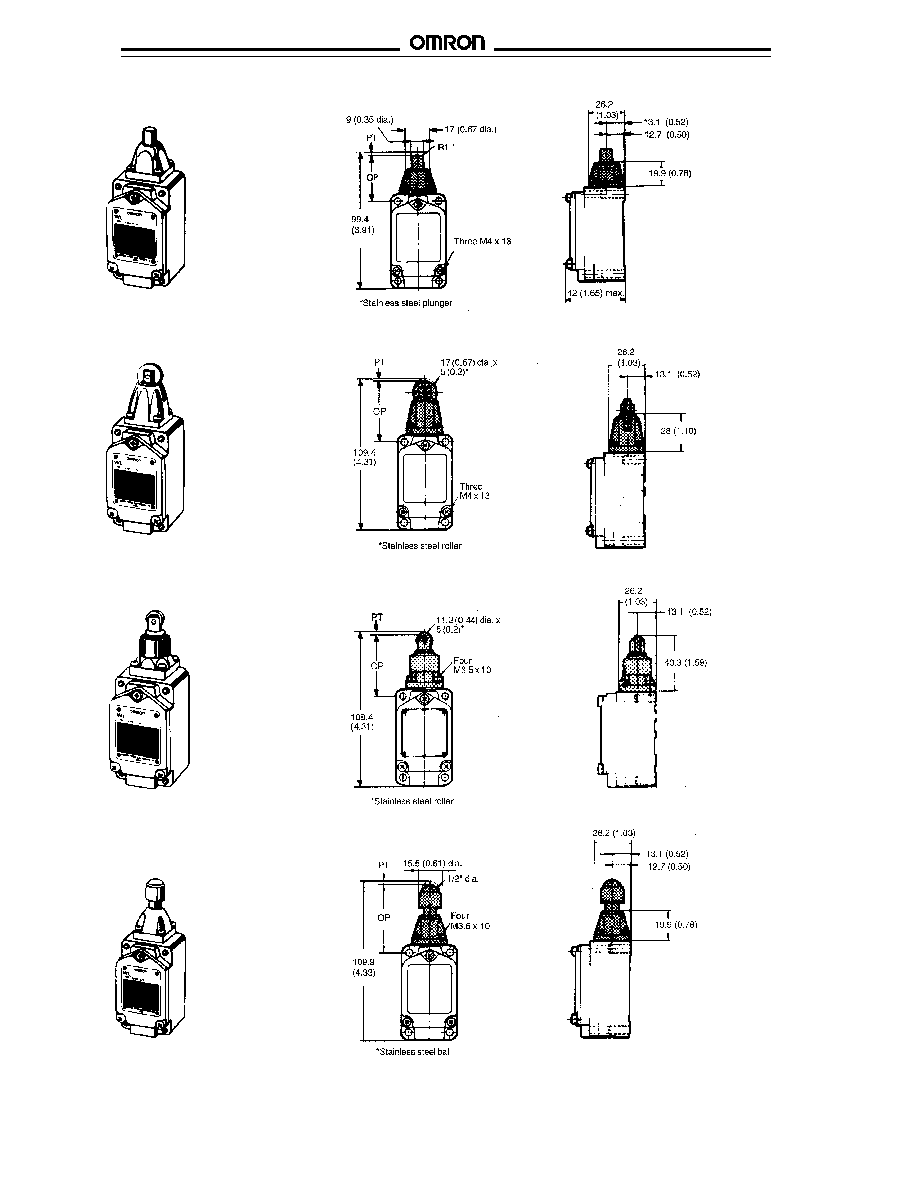
WLD-TS Plain Plunger Switch
WLD2-TS Roller Plunger Switch
WLD28-TS Sealed Roller Plunger Switch
WLD3-TS Ball Plunger Switch
WL
WL
17
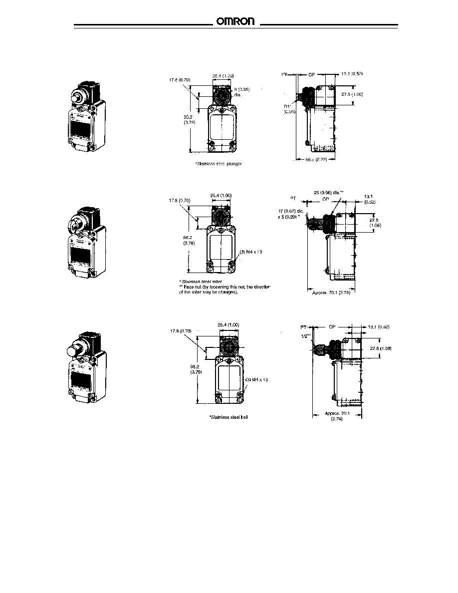
WLSD3-TS Horizontal Ball Plunger Switch
Unit: mm (inch)
WLSD2-TS Horizontal Roller Plunger Switch
WLSD-TS Horizontal Plain Plunger Switch

WL
WL
18
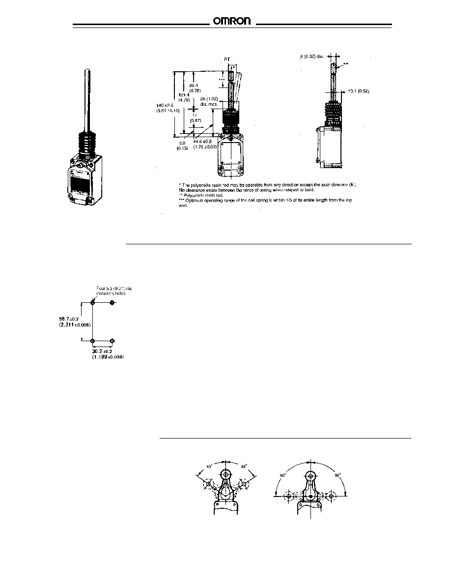
WLNJ-TS Coil Spring Switch
WLNJ-S2TS Steel Wire Switch
WLNJ30-TS Coil Spring Switch
WL
WL
19
Overtravel Type
Standard Limit Switches
Overtravel Limit Switches
Overtravel type limit switches offer a longer
overtravel (OT) to accommodate different
cam shapes. The key difference between
"standard" and "overtravel" is in the angle
of operation: overtravel types can operate
at 90
∞
on either side of the center point.
Standard types are recommended for
operation at 45
∞
on either side of the center
point. However, overtravel type switches
cannot be expected to provide 90
∞
operation on only one side.
Customized Models
Installation
s
MOUNTING HOLES
Most WL Switches
WLNJ-2TS Nylon Rod Switch
Unit: mm (inch)

WL
WL
20
s
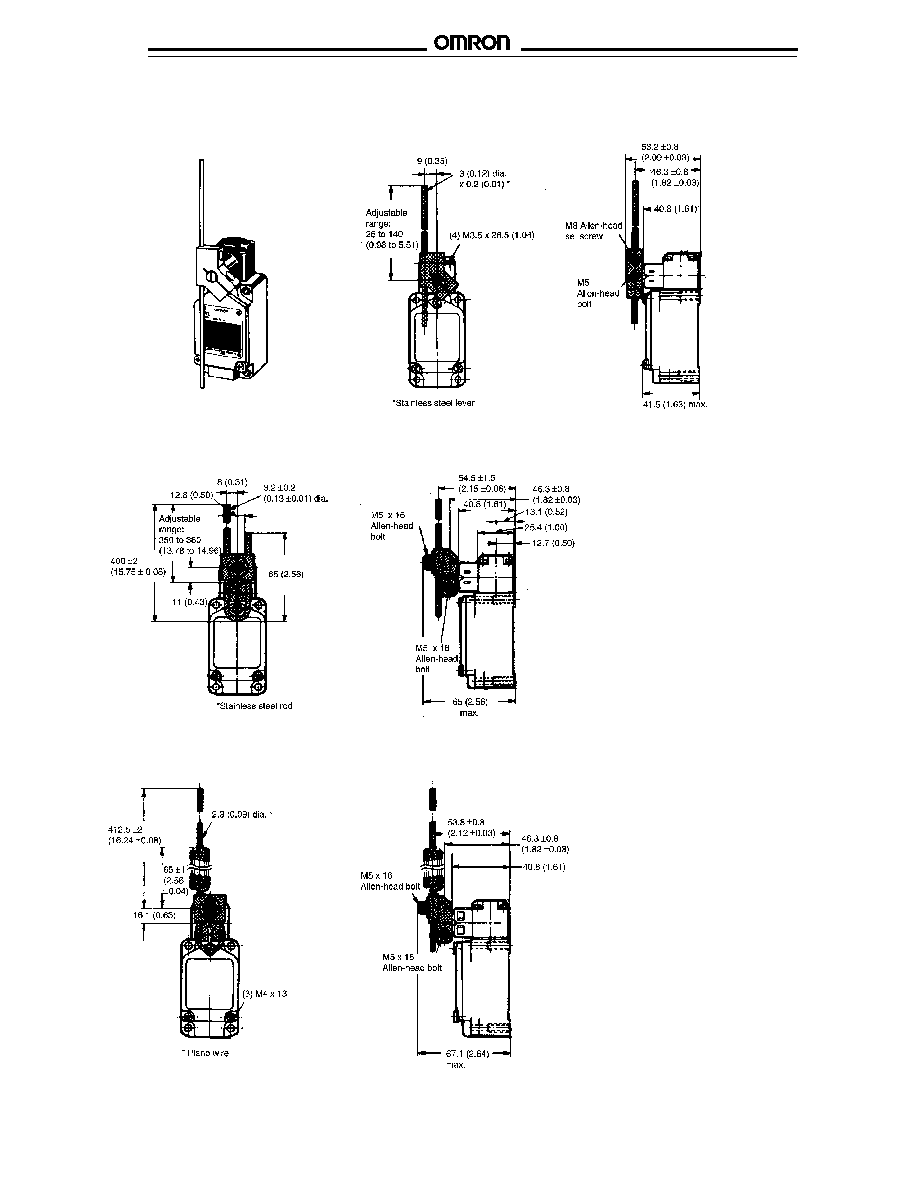
DIMENSIONS
Unit: mm (inch)
WLCA2-2TS Short Roller Lever Overtravel Switch
WLCA12-2TS Adjustable Roller Lever Overtravel Switch
Note:
Levers for WLCAL4-2-TS and WLCAL5-2-TS have a large tare, so positioning the actuator with the bottom up will reduce chattering.
Operating characteristics of WLCA12-2-TS are measured at arm length of 38 mm (1.29 in).
Operating characteristics of WLCL-2-TS are at arm length of 140 mm (5.51 in)
Operating characteristics of WLCAL4-2-TS are measured at rod length of 380 mm (1.25 ft)
Operating characteristics of WLCAL5-2-TS are measured at rod length of 412.5 mm (1.35 ft)
Legend: OF = Operating Force (max.); RF = Reset Force (min.); OT = Overtravel (min.); PT = Pretravel
MD = Movement Differential (max.); OP = Operating Position; TT = Total Travel (min.)
s
OPERATING CHARACTERISTICS
Part number
Description
OF
RF
OT
PT
MD
TT
WLCA2-2-TS
Short roller lever
900 g (31.74 oz.)
50 g (1.76 oz.)
60
∞
25
∞
±
5
∞
16
∞
90
∞
WLCA12-2-TS
Adjustable roller lever
900 g (31.74 oz.)
50 g (1.76 oz.)
60
∞
25
∞
±
5
∞
16
∞
90
∞
WLCL-2-TS
Adjustable rod lever, 140 mm L
260 g (9.17 oz.)
10 g (0.35 oz.)
60
∞
25
∞
±
5
∞
16
∞
90
∞
WLCAL4-2-TS
Adjustable rod lever, 380 mm L
80 g (2.82 oz.)
8 g (0.28 oz.)
60
∞
25
∞
±
5
∞
16
∞
90
∞
WLCAL5-2-TS
Spring
80 g (2.82 oz.)
8 g (0.28 oz.)
60
∞
25
∞
±
5
∞
16
∞
90
∞
WL
WL
21
WLCAL5-2TS Adjustable Spring Lever Overtravel Switch
Unit: mm (inch)
WLCAL4-2TS Long Adjustable Rod Lever Overtravel Switch
WLCL-2TS Adjustable Rod Lever Overtravel Switch

WL
WL
22
Legend: OF = Operating Force (max.); RF = Reset Force (min.); OT = Overtravel (min.); PT = Pretravel;
MD = Movement Differential (max.)
s
OPERATING CHARACTERISTICS
Part number
Description
OF
RF
OT
PT
MD
WLGCA2-TS
Short roller lever
1.3 kg (47.97 oz.)
150 g (5.29 oz.)
40
∞
5
∞
(+2
∞
/-0
∞
)
3
∞
WLGCA2-2-TS
Overtravel short roller lever
900 g (31.74 oz.)
50 g (1.76 oz.)
85
∞
8
∞
max.
3
∞
WLGCA2-7-TS
Medium roller lever
1.04 kg (36.68 oz.)
110 g (3.88 oz.)
40
∞
5
∞
3
∞
WLGCA2-8-TS
Long roller lever
820 g (28.92 oz.)
90 g (3.17 oz.)
40
∞
5
∞
3
∞
WLGCA12-TS
Adjustable roller lever
1.36 kg (47.97 oz.)
150 g (5.29 oz.)
40
∞
5
∞
(+2
∞
/-0
∞
)
3
∞
WLGCL-TS
Adjustable rod lever, 140 mm L
400 g (14.1 oz.)
10 g (0.35 oz.)
40
∞
5
∞
(+2
∞
/-0
∞
)
3
∞
Note:
Operating characteristics of WLGCA12-TS are measured at arm length of 38 mm (1.29 in).
Operating characteristics of WLGCL-TS are at arm length of 140 mm (5.51 in)
s
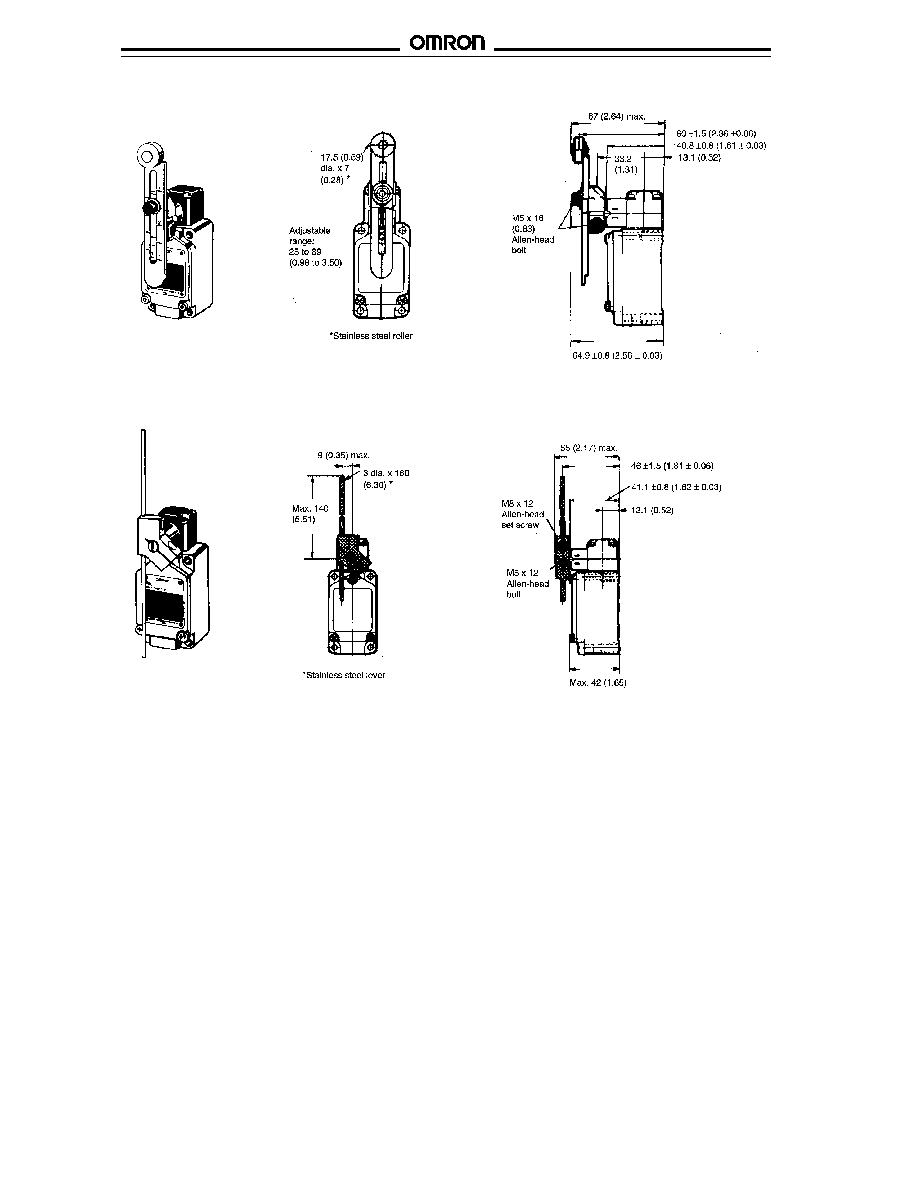
DIMENSIONS
Unit: mm (inch)
WLGCA2-TS Short Roller Lever High Precision Switch
The key differences between "high-
precision" and "standard" limit switches
are in the pretravel (PT) ratings and the
repeat accuracy. High-precision
switches have a pretravel (PT) of 5
∞
compared to 20
∞
for standard switches.
The repeat accuracy is best compared by
referring to the graph at right. High-
precision switches are ideal for position-
ing control in machine tools and other
applications.
High-Precision Type

WL
WL
23
WLGCA2-8TS Long Roller Lever High Precision Switch
Unit: mm (inch)
WLGCA2-7TS Medium Roller Lever High Precision Switch
WLGCA2-2TS Short Overtravel Roller Lever High Precision Switch
WL
WL
24
WLGCL-TS Adjustable Rod Lever High Precision Switch
WLGCA12-TS Adjustable Roller Lever High Precision Switch

WL
WL
OMRON ELECTRONICS LLC
OMRON CANADA, INC.
One East Commerce Drive
885 Milner Avenue
Schaumburg, IL 60173
Scarborough, Ontario M1B 5V8
1-800-55-OMRON
416-286-6465
Cat. No. CEDSAX4
11/01
Specifications subject to change without notice.
Printed in the U.S.A.
OMRON ON-LINE
Global - http://www.omron.com
USA - http://www.omron.com/oei
Canada - http://www.omron.com/oci