
⌐
Semiconductor Components Industries, LLC, 2001
April, 2001 ¡ Rev. 1
1
Publication Order Number:
NCN6010/D
NCN6010
SIM Card Supply and
Level Shifter
The NCN6010 is a level shifter analog circuit designed to translate
the voltages between a SIM Card and an external microcontroller. A
built¡in DC/DC converter makes the NCN6010 useable to drive any
type of SIM card. The device fulfills the GSM 11.11 specification. The
external MPU has an access to a dedicated input STOP pin, providing
a way to switch off the power applied to the SIM card in case of failure
or when the card is removed.
Features
╖
Supports 3.0 V or 5.0 V Operating SIM Card
╖
Built¡in Pull Up Resistor for I/O Pin in Both Directions
╖
All Pins are Fully ESD Protected, According to GSM Specification
╖
Supports 10 MHz Clock
╖
6.0 kV ESD Proof on SIM Card Pins
Typical Applications
╖
Cellular Phone SIM Interface
╖
Identification Module
Figure 1. Typical Interface Application
C8
I/O
GND
V
pp
C4
CLK
RST
V
CC
DET
DET
V
CC
P4
P3
P2
P1
MPU or GSM Controller
1
2
3
4
5
6
7
14
13
12
10
RESET
I/O
CLOCK
SIM_V
CC
SIM_IO
SIM_CLK
SIM_RST
C2
220 nF
1
╡
F
GND
GND
C3
P0
V
DD
STOP
MOD_V
CC
PWR_ON
Cta
Ctb
9
8
11
V
DD
C4
4.7
╡
F
GND
GND
8
7
6
5
4
3
2
1
10
9
GND
Device
Package
Shipping
ORDERING INFORMATION
NCN6010DTB
TSSOP¡14
96 Units/Rail
http://onsemi.com
TSSOP¡14
CASE 948G
1
14
MARKING
DIAGRAM
A = Assembly Location
L
= Wafer Lot
Y = Year
W = Work Week
PIN CONNECTIONS
2
3
4
5
6
7
14
13
12
10
9
(Top View
)
I/O
V
DD
STOP
MOD_VCC
PWR_ON
CLOCK
RESET
SIM_VCC
Cta
GND
SIM_CLK
Ctb
SIM_RST
1
11 SIM_IO
1
14
1
8
NCN
6010
ALYW
NCN6010DTBR2 TSSOP¡14
2500 Tape & Reel

NCN6010
http://onsemi.com
2
GND
STOP
2
PWR_ON
V
CC
SIM_V
CC
V
DD
Cta
I/O
I/O
DATA
DATA
3
4
1
6
7
5
14
13
12
9
8
11
10
ENABLE
3 V/5 V
POWER UNIT & LOGIC
MANAGEMENT
V
CC
20 k
GND
ENABLE
Ctb
SIM_CLK
SIM_RST
SIM_IO
GROUND
MOD_V
CC
PWR_ON
V
DD
CLOCK
RESET
I/O
GND
GND
GND
Figure 2. NCN6010 Block Diagram
20
k

NCN6010
http://onsemi.com
3
PIN DESCRIPTIONS
Pin
Name
Type
Description
1
V
DD
POWER
This pin is connected to the system controller power supply suitable to operate from
a 3.6 V typical battery. A low ESR ceramic capacitor (4.7
m
F typical) shall be used to
bypass the power supply voltage.
2
STOP
INPUT
A Low level on this pin resets the SIM interface, switching off the SIM_VCC,
according to the ISO7816¡3 Power Down procedure (See Table 1 and Figure 3).
3
MOD_V
CC
INPUT
The signal present on this pin programs the SIM_VCC value (See Table 1):
MOD_VCC = L
SIM_VCC = 5.0 V
MOD_VCC = H
SIM_VCC = 3.0 V
4
PWR_ON
INPUT
The signal present on this pin controls the SIM_VCC state (See Table 1):
PWR_ON = L
SIM_VCC = Open, no supply connected to the SIM card.
PWR_ON = H
SIM_VCC = Active, the card is powered.
5
I/O
INPUT
This pin is connected to an external microcontroller or GSM management unit. A
bi¡directional level translator adapts the serial I/O signal between the smart card and
the external controller. A built¡in constant 20 k
(typical) resistor provides a high
impedance state when not activated.
6
CLOCK
INPUT
The clock signal, coming from the external controller, must have a Duty Cycle within
the Min/Max values defined by the specification (typically 50%). The built¡in level
shifter translates the input signal to the external SIM card CLK input.
7
RESET
INPUT
The RESET signal present at this pin is connected to the SIM card. The internal level
shifter translates the level according to the voltages present at pin 1 and the
SIM_VCC programmed value.
8
SIM_RST
OUTPUT
This pin is connected to the RESET pin of the card connector. A level translator
adapts the external RESET signal to the SIM card. A built¡in active pull down
connects this pin to ground when the device is in a nonoperating mode.
9
SIM_CLK
OUTPUT
This pin is connected to the CLK pin of the card connector. The CLOCK signal
comes from the external clock generator, the internal level shifter being used to
adapt the voltage defined for the SIM_VCC. A built¡in active pull down connects this
pin to ground when the device is in a nonoperating mode.
10
GND
GROUND
This pin is the GROUND reference for the integrated circuit and associated signals.
Cares must be observed to avoid voltage spikes when the device operates in a
normal operation.
11
SIM_I/O
This pin handles the connection to the serial I/O of the card connector. A
bi¡directional level translator adapts the serial I/O signal between the card and the
microcontroller. A 20 k
(typical) pull up resistor provides a High impedance state for
the SIM card I/O link.
12
Cta
POWER
This pin is connected to the external capacitor used by the internal Charge Pump
converter. Using Low ESR ceramic type is recommended (X5R or X7R).
13
Ctb
POWER
This pin is connected to the external capacitor used by the internal Charge Pump
converter. Using Low ESR ceramic type is recommended (X5R or X7R).
14
SIM_VCC
POWER
This pin is connected to the SIM card power supply pin. An internal Charge Pump
converter is programmable by the external MPU to supply either 3.0 V or 5.0 V
output voltage. An external 1.0
╡
F minimum ceramic capacitor (ESR
t
100 m
W
,
X5R or X7R recommended) must be connected across SIM_VCC and GND.
During a normal operation, the SIM_VCC voltage can be set to 3.0 V followed by a
5.0 V value, or can start directly to any of these two values. When the voltage is
adjusted downward (from 5.0 V to 3.0 V) cares must be observed as reverse peak
current can flow from the external capacitors to the battery during a short amount of
time (in the 1.0
╡
s range). When such a voltage adjustment is necessary, it is
recommended to force SIM_VCC to zero, wait 350
╡
s minimum, then reprogram the
chip to get SIM_VCC = 3.0 V.

NCN6010
http://onsemi.com
4
MAXIMUM RATINGS
(Note 1.)
Rating
Symbol
Value
Unit
Power Supply
V
DD
7.0
V
External Card Power Supply and Level Shifter
SIM_VCC
7.0
V
Digital Input Voltage
Digital Input Current
STOP
¡0.3
v
V
v
V
DD
1.0
V
mA
Digital Input Voltage
Digital Input Current
RESET
¡0.3
v
V
v
V
DD
1.0
V
mA
Digital Input Voltage
Digital Input Current
CLOCK
¡0.3
v
V
v
V
DD
1.0
V
mA
Digital Input Voltage
Digital Input Current
I/O
¡0.3
v
V
v
V
DD
1.0
V
mA
Digital Output Voltage
Digital Output Current
SIM_RST
¡0.3
v
V
v
SIM_VCC
25
V
mA
Digital Input/Output Voltage
Digital Input/Output Current
SIM_I/O
¡0.3
v
V
v
SIM_VCC
25
V
mA
Digital Output Voltage
Digital Output Current
SIM_CLK
¡0.3
v
V
v
SIM_VCC
50
V
mA
Human Body Model: R = 1500
, C = 100 pF
SIM card side, pins 8, 9, 11 & 14
All other pins
ESD
6.0
2.0
kV
kV
TSSOP¡14 Package
Power Dissipation @ T
A
= +85
░
C
Thermal Resistance Junction to Air
P
D
R
THhja
275
145
mW
░
C/W
Operating Ambient Temperature Range
T
A
¡25 to +85
░
C
Operating Junction Temperature Range
T
J
¡25 to +125
░
C
Maximum Junction Temperature
T
Jmax
+150
░
C
Storage Temperature Range
T
stg
¡65 to +150
░
C
1. Maximum electrical ratings are defined as those values beyond which damage to the device may occur at T
A
= +25
░
C.

NCN6010
http://onsemi.com
5
POWER SUPPLY SECTION
(¡25
5
C to +85
5
C)
Rating
Symbol
Pin
Min
Typ
Max
Unit
Power Supply
V
DD
1
2.7
¡
3.6
V
Standby Supply Current @ No Input Clock, All Input
Logic to H, No Load Connected to the SIM Interface.
I V
DD
1
¡
500
¡
nA
Ground Current, @ V
DD
= 3.0 V, Operating Conditions:
PWR_ON = 0
SIM_VCC = 5.0 V, I
CC
= 0 mA
SIM_VCC = 5.0 V, I
CC
= 10 mA (Note 2.)
SIM_VCC = 3.0 V, I
CC
= 0 mA
SIM_VCC = 3.0 V, I
CC
= 6.0 mA (Note 2.)
I V
DD
1
¡
200
40
5.0
125
25
╡
A
External Card Power Supply at 5.0 V
@ 2.7 V
v
V
DD
v
3.6 V, I
CC
= 10 mA
External Card Power Supply at 3.0 V
@ 2.7 V
v
V
DD
v
3.6 V, I
CC
= 10 mA
SIM_VCC
14
4.5
V
DD
¡ 50 mV
V
DD
¡ 25 mV
5.5
V
DD
V
Output SIM Card Supply Voltage Turn On Time
Ct = 220 nF, Cout1 = 1.0
╡
F
"
20%
V
DD
= 3.0 V, SIM_VCC = 5.0 V
V
DD
= 3.0 V, SIM_VCC = 3.0 V
VCC
TON
14
¡
0.5
1.0
ms
Output SIM Card Supply Voltage Turn Off Time
Ct = 220 nF, Cout1 = 1.0
╡
F
"
20% (Note 3.)
V
DD
= 2.7 V, SIM_VCC = 5.0 V, @ V
LOW
= 0.4 V
V
DD
= 2.7 V, SIM_VCC = 3.0 V, @ V
LOW
= 0.4 V
VCC
TOFF
14
¡
¡
300
300
╡
s
Output Voltage Ripple (Note 4.)
Ct = 220 nF, Cout1 = 1.0
╡
F, Cout2 = 100 nF
V
DD
= 3.0 V, SIM_VCC = 5.0 V, I
CC
= 10 mA
(Not Relevant at SIM_VCC = 3.0 V)
VCC
RIP
14
¡
¡
200
mV
Input Peak Current During DC/DC Startup
@ V
DD
= 3.0 V, SIM_VCC = 5.0 V
I
DDpk
1
¡
300
¡
mA
Input Average Current During Normal Operation,
@ V
DD
= 3.0 V, SIM_VCC = 5.0 V
I
DDavg
1
¡
20
¡
mA
DC/DC Internal Oscillator
Fosc
¡
¡
800
¡
kHz
2. The I
DD
current represents the absolute difference between the current absorbed by the load and the one absorbed by the chip.
3. A 350
╡
s delay must be observed by the external MPU prior to reactivate the SIM_VCC output.
4. Using low ESR capacitors type (max 100 m
) is mandatory for Ct, Cout1 and Cout2 to reach the NCN6010 specifications. Ceramic type
(X5R or X7R) are recommended.
DIGITAL INPUT SECTION CLOCK, RESET, I/O, STOP, MOD_VCC, PWR_ON
Rating
Symbol
Pin
Min
Typ
Max
Unit
High Level Input Voltage
Low Level Input Voltage
Input Rise Time
Input Fall Time
Input Capacitance
V
IH
V
IL
tr
tf
Cin
2, 3
4, 5
6, 7
0.7 * V
DD
¡
V
DD
0.3 * V
DD
50
50
10
V
V
ns
ns
pF
Input @ 45% < Duty Cycle < 55%
Clock Rise Time
Clock Fall Time
Input Clock Capacitance
CLOCK
6
¡
¡
5.0
50
50
10
MHz
ns
ns
pF
Input/Output Data Transfer Frequency
I/O Rise Time
I/O Fall Time
Input I/O Capacitance
I/O
5
¡
15
160
0.8
0.8
10
kHz
╡
s
╡
s
pF

NCN6010
http://onsemi.com
6
SIM INTERFACE SECTION
(Note 7.)
Rating
Symbol
Pin
Min
Typ
Max
Unit
SIM_VCC = +5.0 V
Output RESET V
OH
@ Isim_rst = +200
╡
A
Output RESET V
OL
@ Isim_rst = ¡200
╡
A
Output RESET Rise Time @ Cout = 50 pF
Output RESET Fall Time @ Cout = 50 pF
SIM_VCC = +3.0 V
Output RESET V
OH
@ Isim_rst = +200
╡
A
Output RESET V
OL
@ Isim_rst = ¡200
╡
A
Output RESET Rise Time @ Cout = 50 pF
Output RESET Fall Time @ Cout = 50 pF
SIM_RST
Note 5.
8
SIM_VCC ¡ 0.7
0
0.8 * SIM_VCC
0
¡
SIM_VCC
0.6
400
400
SIM_VCC
0.2 * SIM_VCC
400
400
V
V
ns
ns
V
V
ns
ns
SIM_VCC = +5.0 V
Output Duty Cycle
Output Frequency
Output SIM_CLK Rise Time @ Cout = 50 pF
Output SIM_CLK Fall Time @ Cout = 50 pF
Output V
OH
@ Isim_clk = +20
╡
A
Output V
OL
@ Isim_clk = ¡200
╡
A
SIM_VCC = +3.0 V
Output Duty Cycle
Output Frequency
Output SIM_CLK Rise Time @ Cout = 50 pF
Output SIM_CLK Fall Time @ Cout = 50 pF
Output V
OH
@ Isim_clk = +20
╡
A
Output V
OL
@ Isim_clk = ¡20
╡
A
SIM_CLK
Note 5.
Note 6.
9
40
0.7 * SIM_VCC
0
40
0.7 * SIM_VCC
0
¡
60
5.0
18
18
SIM_VCC
0.5
60
5.0
18
18
SIM_VCC
0.2 * SIM_VCC
%
MHz
ns
ns
V
V
%
MHz
ns
ns
V
V
SIM_VCC = +5.0 V
SIM_I/O Data Transfer Frequency
SIM_I/O Rise Time @ Cout = 50 pF
SIM_I/O Fall Time @ Cout = 50 pF
Output V
OH
@ I
SIM_IO
= +20
╡
A, V
IH
= V
DD
Output V
OL
@ I
SIM_IO
= ¡1.0 mA,
V
IL
I/O = 0 V
SIM_VCC = +3.0 V
SIM_I/O Data Transfer Frequency
SIM_I/O Rise Time @ Cout = 50 pF
SIM_I/O Fall Time @ Cout = 50 pF
Output V
OH
@ I
SIM_IO
= +20
╡
A, V
IH
= V
DD
Output V
OL
@ I
SIM_IO
= ¡1.0 mA,
V
IL
I/O = 0 V
SIM_I/O
11
0.7 * SIM_VCC
0
0.7 * SIM_VCC
0
15
15
160
0.8
0.8
SIM_VCC
0.4
160
0.8
0.8
SIM_VCC
0.4
kHz
╡
s
╡
s
V
V
kHz
╡
s
╡
s
V
V
I/O Pull Up Resistor
I/O_
RP
5
13
20
¡
k
Card I/O Pull Up Resistor
SIM_I/O_
RP
11
13
20
¡
k
5. Internal NMOS device, biased to V
DD
, provides low impedance when SIM_V
CC
is disconnected to sustain GSM 11.11¡200
╡
A input current
test.
6. The SIM_CLK clock can operate up to 10 MHz, but the rise and fall time are not guaranteed to be fully within the ISO7816 specification over
the temperature range. Typically, tr and tf are 12 ns @ CRD_CLK = 10 MHz.
7. Digital inputs undershoot
t
¡0.30 V, Digital inputs overshoot
t
0.30 V.

NCN6010
http://onsemi.com
7
Card Supply Charge Pump Converter
The NCN6010 device provides three pins to control the
operation of the interface as depicted in Table 1. The built¡in
charge pump converter circuit provides either a 3.0 V or a
5.0 V output voltage as defined by the programming mode.
The external capacitor connected across pins 12 and 13 is
used to generate the step up voltage. Since the device
operates at 800 kHz typically, one must use high quality,
Low ESR type, ceramic capacitor (220 nF recommended).
The second external capacitor, connected across pin 14 and
GND, smooths the output voltage coming from the Charge
Pump. A high quality, Low ESR capacitor is necessary to
achieve the SIM_VCC ripple voltage (1.0
╡
F Ceramic type
is recommended).
The setting of the SIM_VCC voltage, using MOD_VCC
= 0 or 1, can only be made when PWR_ON is Low.
Consequently, a new supply voltage adjustment is
performed by first deactivating the SIM card, followed by
reactivating it with the new supply voltage. The SIM_VCC
voltage can be reprogrammed straightforward when the
output voltage increases from 3.0 V to 5.0 V. On the other
hand, although it is possible to change the SIM_VCC
voltage from 5.0 V to 3.0 V, it is recommended to switch off
the Charge Pump prior to reprogram the SIM_VCC voltage
from the high 5.0 V to a low 3.0 V.
The DC/DC converter operates under two modes as
defined by the logic level present at MOD_VCC/pin 3:
MOD_VCC = 0 SIM_CC = 5.0 V,
"10%. This is the
default condition at start up.
MOD_VCC = 1 The Charge Pump is not activated and the
SIM_VCC voltage is equal to the V
DD
supply minus the internal maximum
50 mV drop.
The NCN6010 provides a POWER DOWN sequence,
according to the ISO7816¡3 specification.
Since a built¡in active pull down MOS pull the SIM_VCC
pin to ground when the smart card is deactivated, a 350
╡
s
minimum delay must be observed prior to reactivate the
power supply. This timing assumes a 1.0
╡
F external
reservoir capacitor connected across SIM_VCC and
Ground.
Table 1. Programming Functions
STOP
MOD_VCC
PWR_ON
Operation Mode
0
X
X
The SIM card supply is disabled, the SIM_VCC pin is Open, SIM_RST = L,
SIM_I/O = L, SIM_CLK = L
1
0
0
The NCN6010 is in the power down mode. The SIM card supply is disabled,
SIM_VCC = Open, SIM_RST = L, SIM_CLK = L, SIM_IO = L.
The SIM_VCC voltage is programmed to 5.0 V.
1
1
0
The NCN6010 is in the power down mode. The SIM card supply is disabled,
SIM_VCC = Open, SIM_RST = L, SIM_CLK = L, SIM_IO = L.
The SIM_VCC voltage is programmed to 3.0 V.
1
X
1
The NCN6010 is in normal operating mode. The SIM card supply is enabled, SIM_VCC
voltage is the one previously programmed, all the SIM interface pins are active.
Table 1: Programming Mode
When the card is removed, the STOP pin shall be asserted
Low to disable the NCN6010. A mechanical switch, or
equivalent, can be either sensed by the MPU, or directly
connected to pin 2, to handle the procedure.
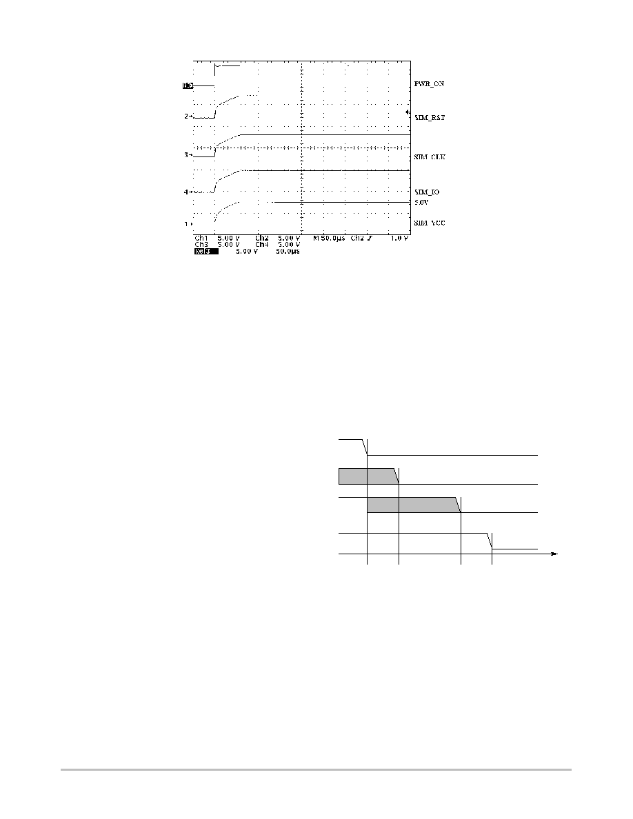
Power Up Sequence
When the charge pump is activated, MOD_VCC = Low,
the SIM card related level shifter pins are biased to the 5.0 V
voltage. When the output voltage starts from zero, as
depicted in Figure 3, a 50
ms stabilization delay (typical) is
necessary to make sure all the output signals are biased at the
nominal 5.0 V voltage. To avoid a card transaction error, the
user must take this delay into account and program the chip
accordingly.
NCN6010
http://onsemi.com
8
Figure 3. Power On Sequence
Power Down Operation
The power down mode can be initiated by either the
PWR_ON or by the STOP pin condition. In both cases, the
communication I/O session is terminated immediately,
according to the ISO7816¡3 sequence as depicted in
Figure 4. When the PWR_ON signal is set Low, the
NCN6010 goes to the power down mode. According to the
ISO7816¡3 procedure defined to deactivate the SIM
contacts, the input pins I/O, CLOCK and RESET must be
Low before the PWR_ON is taken Low. When the
PWR_ON is Low, the SIM_IO, SIM_CLK and SIM_RST
pins are forced to Low and the SIM_VCC pin is left floating.
When the STOP signal is Low, the SIM_IO, SIM_CLK
and SIM_RST are forced Low, the SIM_VCC being left
floating, until the STOP pin is taken High again.
When the card is extracted, the external MPU shall detect
the operation and run the Power Down of the card by forcing
PWR_ON input to Low. The NCN6010 fulfills the power
sequence as defined by the ISO/CEI 7816¡3 norm (see
oscillogram given in Figure 5).
SIM_V
CC
SIM_CLK
SIM_RST
SIM_IO
UNDEFINED
T0
T1
T2
T3
T
Force SIM_RST to Low
Force SIM_CLK to Low, unless it is already in this state
Force SIM_IO to Low
Shut Off the SIM_V
CC
supply
Figure 4. ISO7816¡3 Power Down Sequence

NCN6010
http://onsemi.com
9
Figure 5. Power Down Sequence Oscillogram
Level Shifters
When the SIM card voltage is either higher or lower than
the MPU V
DD
supply, the level shifters can be
reprogrammed to cope with the expected output voltage.
When the MPU and the SIM card operate under the same
supply voltage, the DC/DC converter is not activated
(SIM_VCC = V
DD
¡50 mV) and the signals go directly
through the level shifters.
The bi¡directional I/O line provides a way to
automatically
adapt the voltage difference between the
╡
CU
and the SIM card. In addition with the pull up resistor, an
active pull up circuit (Figure 6 Q1 and Q2) provides a fast
charge of the stray capacitance, yielding a rise time fully
within the ISO/EMV specifications.
Figure 6. Basic I/O Line Interface
GND
V
DD
I/O
20 k
20 k
SIM_IO
V
CC
LOGIC
IO/CONTROL
200 ns
200 ns
GND
Q3
Q1
Q2
The typical waveform provided in Figure 7 shows how the
accelerator operates. During the first 200 ns (typical), the
slope of the rise time is solely a function of the pull up
resistor associated with the stray capacitance. During this
period, the PMOS devices are not activated since the input
voltage is below their Vgs threshold. When the input slope
crosses the Vgsth, the opposite one shot is activated,
providing a low impedance to charge the capacitance, thus
increasing the rise time as depicted in Figure 7. The same
mechanism applies for the opposite side of the line to make
sure the system is optimum.

NCN6010
http://onsemi.com
10
Figure 7. SIM_IO Rise and Fall Time Oscillogram
Input Schmitt Triggers
All the Logic Input pins have built¡in Schmitt trigger
circuits to prevent the NCN6010 against uncontrolled
operation. The typical dynamic characteristics of the related
pins are depicted in Figure 8.
The output signal is guaranteed to go High when the input
voltage is above 0.70*Vbat, and will go Low when the input
voltage is below 0.30 * Vbat.
Figure 8. Typical Schmitt Trigger Characteristic
Output
V
bat
ON
OFF
0.30
V
bat
0.70 V
bat
V
bat
Input
Charge Pump Converter
The converter uses a switched capacitor technique to
increase the SIM_VCC voltage up to 5.0 V from a 3.3 V
typical battery. The concept, depicted in Figure 9, charges
the transfer capacitor C1 up to the Vcc value, then connects
this capacitor is series with the input voltage¡output
reservoir network. The voltage developed across the load is,
theoretically, twice the battery voltage, but the system must
takes into account the losses associated with the power
switches and the internal ohmic drops.
S1
S4
S5
C1
B
S3
S2
C2
V
CC
V
O
LOAD
I
S
A
Figure 9. Basic Charge Pump Converter
When the output voltage is programmed to 3.0 V, the
clocks are inactive and the load is directly connected to the
battery by means of switch S5. The SIM_VCC voltage
follows the input value, minus the drop coming from the
internal resistance . The current is limited by the Ron of the
power device S5 and t he output voltage will decrease as the
load current increases above 20 mA (typical). Figure 10
illustrates the theoretical waveforms.

NCN6010
http://onsemi.com
11
Figure 10. Basic Charge Pump Operating Timings
SIM_V
CC
= 5.0 V
S1
S2
S3
S4
S5
SIM_V
CC
= 3.0 V
MOD_V
CC
When the NCN6010 is programmed in the 5.0 V output
voltage, the clocks are activated, switch S5 is disconnected
and the output voltage is the result of the C1 charge transfer
into the output load. The current is limited by three mains
parameters:
¡ the Ron of the switching MOS (S1 through S4)
¡ the operating frequency
¡ the C1/C2 ratio and their ESR
The first parameters are depending upon the internal
structure and size of the NMOS/PMOS devices used to
design the chip. The third parameter is adjustable by the user
and, beside the micro farad values, the type of capacitors
plays a significant role. As a matter of fact, using a low cost
electrolytic model will ruin the efficiency due to the high
ESR of such a capacitor. It is highly recommended to use
ceramic types, preferably from the X5R or X7R series, to
achieve the efficiency and the SIM_VCC output voltage
ripple. Table 2 summarizes the characteristics of the most
common type of capacitors.
Table 2. Comparison of Capacitor Types
Manufacturers
Type/Serie
Format
Max Value
Tolerance
Typ. Z @ 500 kHz
MURATA
CERAMIC/GRM225
0805
10
m
F/6.3 V
+80%/¡20%
30 m
W
VISHAY
Tantalum/594C/593C
1206
10
m
F/16 V
¡
450 m
W
VISHAY
Electrolytic/94SV
1206
10
m
F/10 V
¡20%/+20%
400 m
W

NCN6010
http://onsemi.com
12
It is clear that, with nearly half an ohm of resistance is
series with the pure capacitor, the tantalum or the electrolytic
type will generate high voltage spikes and poor regulation in
the high frequency operating charge pump built into the
NCN6010. Moreover, with ESR in the 3.0 Ohm range, low
cost capacitors are not suitable for this application.
Figure 11 provides the schematic diagram of the simulated
charge pump circuit. Although this schematic does not
represent the accurate internal structure of the NCN6010, it
can be used for engineering purpose. The ABM devices S1,
S2, S4 and S5 have been defined in the PSPICE model to
represent the NMOS and PMOS used in the silicon. The
ESR value of C2 and C3 can be adjusted, at PSPICE level,
to cope with any type of external capacitors and are useful
to double check the behavior of the system as a function of
the external passives components.
+
+
¡
+
¡
+
¡
+
¡
+
¡
+
¡
S1
U1A
74HC08
1
2
3
U3A
74HC14
1
2
U2A
74HC14
1
2
S2
V1
275 V
V2
V1 = 0
Transfer Capacitor
S4
E5
EVALUE
S5
Battery Pack
V3
5.0 V
¡
+
+
¡
TD = 10 ns
TR = 10 ns
TF = 10 ns
PW = 600 ns
PER = 1200 ns
+
¡
+
¡
+
¡
OUT+ IN+
OUT¡ IN¡
R1
0.1 R
C1
4.7
╡
F
IC = 0
S
V
OFF
= 0.0 V
V
ON
= 1.0 V
S
V
OFF
= 2.0 V
V
ON
= 0.0 V
R2
0.1 R
C2
1
╡
F
R4
0.05 R
C3
220 nF
S
V
ON
= 1.0 V
V
OFF
= 0.0 V
S
V
OFF
= 2.0 V
V
ON
= 0.0 V
R3
0.5 R
Figure 11. Charge Pump Simulation Schematic Diagram
if (V (%IN+, %IN¡) > 80 mV, 5, 0)
R5
500 R
LOAD
V2 = 3
NCN6010
http://onsemi.com
13
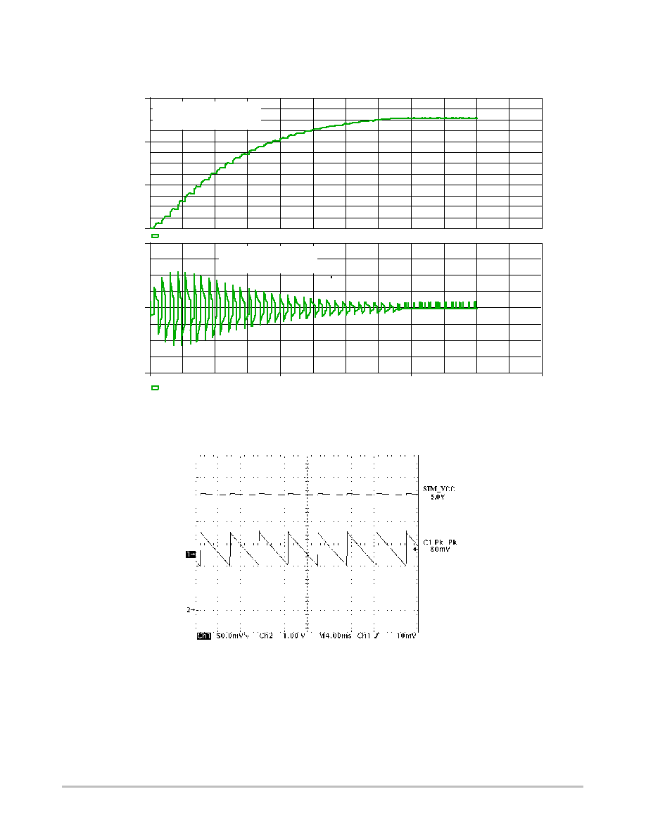
The operating waveforms are given in Figure 12 to
illustrate the high peak current flowing in the transfer
capacitor. The real ripple voltage, coming from the
engineering board, is given in Figure 13.
TIME (
╡
s)
I(R4)
¡2.0 A
0 A
2.0 A
SEL>>
V(C2:2)
0 V
2.0 V
4.0 V
6.0 V
SIM_V
CC
Output Voltage
Load = 10 mA
Charge Pump Transfer
Capacitor Current
0
20
40
60
Figure 12. Simulated Charge Pump Typical Waveforms
Figure 13. SIM_VCC Output Voltage Ripple @ Iout = 10 mA

NCN6010
http://onsemi.com
14
Figure 14. Engineering Test Board
1
2
3
4
5
6
7
14
13
12
10
RESET
I/O
CLOCK
SIM_V
CC
SIM_IO
SIM_CLK
SIM_RST
C4
220 nF
U1
NCN6010
V
DD
STOP
MOD_V
CC
PWR_ON
Cta
Ctb
9
8
11
GND
TP6
TP7
TP8
TP9
RST
CLK
S_IO
VCC
17
18
8
4
3
2
1
5
7
SMARTCARD
J2
Swa
Swb
C8
C4
CLK
RST
V
CC
GND
I/O
V
PP
ISO7816
6
C1
47
╡
F
C2
1.0
╡
F
C3
100 nF
GND
GND
S2
POL. DET
+3.3 V
R2
10 k
POL. DET
+3.3 V
+3.3 V
S1
B7
B6
B5
B4
B3
B2
B1
B0
Y7
D6
D5
D4
D3
D2
D1
D0
26
25
24
23
22
21
20
19
18
17
16
15
14
13
12
11
10
9
8
7
6
5
4
3
2
1
R4
100 R
CLK
RST
I/O
PWR_ON
R3
1 k
TP1
E
TP2
RST
TP3
I/O
TP4
PWR
TP5
MOD
C5
100 nF
GND
+3.3 V
MOD_V
CC
GND
V
DD
ON
470 R
MANUAL PWR_ON
MANUAL MOD_V
CC
S4
S3
+3.3 V
+3.3 V
R5
10 k
R6
10 k
GND
J1
1
1
1
1
1
1
1
1
1
GND
GND
E
IRQ
GND

NCN6010
http://onsemi.com
15
The layout of the PCB is a key parameter to avoid the
voltage spikes that could pollute the rest of the system.
Figure 16 represents a typical printed circuit lay out, based
on the schematic diagram given in Figure 14, highlighting
the large ground plane used in this engineering tool.
Obviously, a GSM application will use much less area, but
cares must be observed to locate the capacitors as close as
possible to the integrated circuit associated pins.
Capacitors C1, C2, C3, C4 and C5 are ceramic, X7R, 10 V,
surface mount.
Figure 15. Engineering Test Board Silk Layer
Figure 16. Engineering Test Board Top Layer
NCN6010
http://onsemi.com
16
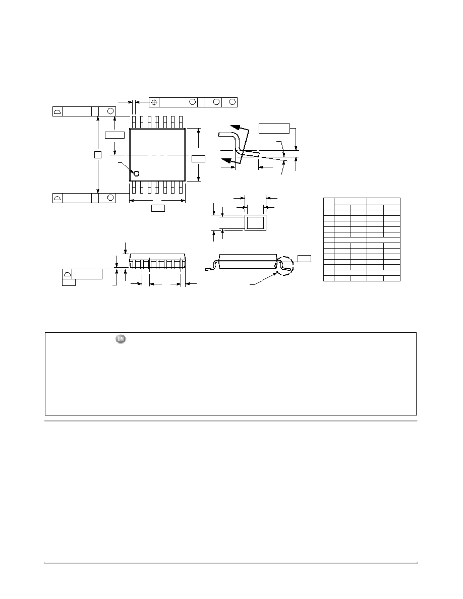
PACKAGE DIMENSIONS
TSSOP¡14
CASE 948G¡01
ISSUE O
DIM
MIN
MAX
MIN
MAX
INCHES
MILLIMETERS
A
4.90
5.10
0.193
0.200
B
4.30
4.50
0.169
0.177
C
---
1.20
---
0.047
D
0.05
0.15
0.002
0.006
F
0.50
0.75
0.020
0.030
G
0.65 BSC
0.026 BSC
H
0.50
0.60
0.020
0.024
J
0.09
0.20
0.004
0.008
J1
0.09
0.16
0.004
0.006
K
0.19
0.30
0.007
0.012
K1
0.19
0.25
0.007
0.010
L
6.40 BSC
0.252 BSC
M
0
8
0
8
NOTES:
1. DIMENSIONING AND TOLERANCING PER ANSI
Y14.5M, 1982.
2. CONTROLLING DIMENSION: MILLIMETER.
3. DIMENSION A DOES NOT INCLUDE MOLD FLASH,
PROTRUSIONS OR GATE BURRS. MOLD FLASH
OR GATE BURRS SHALL NOT EXCEED 0.15
(0.006) PER SIDE.
4. DIMENSION B DOES NOT INCLUDE INTERLEAD
FLASH OR PROTRUSION. INTERLEAD FLASH OR
PROTRUSION SHALL NOT EXCEED
0.25 (0.010) PER SIDE.
5. DIMENSION K DOES NOT INCLUDE DAMBAR
PROTRUSION. ALLOWABLE DAMBAR
PROTRUSION SHALL BE 0.08 (0.003) TOTAL IN
EXCESS OF THE K DIMENSION AT MAXIMUM
MATERIAL CONDITION.
6. TERMINAL NUMBERS ARE SHOWN FOR
REFERENCE ONLY.
7. DIMENSION A AND B ARE TO BE DETERMINED
AT DATUM PLANE -W-.
_
_
_
_
S
U
0.15 (0.006) T
2X
L/2
S
U
M
0.10 (0.004)
V
S
T
L
¡U¡
SEATING
PLANE
0.10 (0.004)
¡T¡
╟╟
╟╟
SECTION N¡N
DETAIL E
J J1
K
K1
╔╔
╔╔
DETAIL E
F
M
¡W¡
0.25 (0.010)
8
14
7
1
PIN 1
IDENT.
H
G
A
D
C
B
S
U
0.15 (0.006) T
¡V¡
14X REF
K
N
N
ON Semiconductor and are trademarks of Semiconductor Components Industries, LLC (SCILLC). SCILLC reserves the right to make changes
without further notice to any products herein. SCILLC makes no warranty, representation or guarantee regarding the suitability of its products for any particular
purpose, nor does SCILLC assume any liability arising out of the application or use of any product or circuit, and specifically disclaims any and all liability,
including without limitation special, consequential or incidental damages. "Typical" parameters which may be provided in SCILLC data sheets and/or
specifications can and do vary in different applications and actual performance may vary over time. All operating parameters, including "Typicals" must be
validated for each customer application by customer's technical experts. SCILLC does not convey any license under its patent rights nor the rights of others.
SCILLC products are not designed, intended, or authorized for use as components in systems intended for surgical implant into the body, or other applications
intended to support or sustain life, or for any other application in which the failure of the SCILLC product could create a situation where personal injury or
death may occur. Should Buyer purchase or use SCILLC products for any such unintended or unauthorized application, Buyer shall indemnify and hold
SCILLC and its officers, employees, subsidiaries, affiliates, and distributors harmless against all claims, costs, damages, and expenses, and reasonable
attorney fees arising out of, directly or indirectly, any claim of personal injury or death associated with such unintended or unauthorized use, even if such claim
alleges that SCILLC was negligent regarding the design or manufacture of the part. SCILLC is an Equal Opportunity/Affirmative Action Employer.
PUBLICATION ORDERING INFORMATION
CENTRAL/SOUTH AMERICA:
Spanish Phone: 303¡308¡7143 (Mon¡Fri 8:00am to 5:00pm MST)
Email: ONlit¡spanish@hibbertco.com
Toll¡Free from Mexico: Dial 01¡800¡288¡2872 for Access ¡
then Dial 866¡297¡9322
ASIA/PACIFIC: LDC for ON Semiconductor ¡ Asia Support
Phone: 1¡303¡675¡2121 (Tue¡Fri 9:00am to 1:00pm, Hong Kong Time)
Toll Free from Hong Kong & Singapore:
001¡800¡4422¡3781
Email: ONlit¡asia@hibbertco.com
JAPAN: ON Semiconductor, Japan Customer Focus Center
4¡32¡1 Nishi¡Gotanda, Shinagawa¡ku, Tokyo, Japan 141¡0031
Phone: 81¡3¡5740¡2700
Email: r14525@onsemi.com
ON Semiconductor Website: http://onsemi.com
For additional information, please contact your local
Sales Representative.
NCN6010/D
NORTH AMERICA Literature Fulfillment:
Literature Distribution Center for ON Semiconductor
P.O. Box 5163, Denver, Colorado 80217 USA
Phone: 303¡675¡2175 or 800¡344¡3860 Toll Free USA/Canada
Fax: 303¡675¡2176 or 800¡344¡3867 Toll Free USA/Canada
Email: ONlit@hibbertco.com
Fax Response Line: 303¡675¡2167 or 800¡344¡3810 Toll Free USA/Canada
N. American Technical Support: 800¡282¡9855 Toll Free USA/Canada
EUROPE: LDC for ON Semiconductor ¡ European Support
German Phone: (+1) 303¡308¡7140 (Mon¡Fri 2:30pm to 7:00pm CET)
Email: ONlit¡german@hibbertco.com
French Phone: (+1) 303¡308¡7141 (Mon¡Fri 2:00pm to 7:00pm CET)
Email: ONlit¡french@hibbertco.com
English Phone: (+1) 303¡308¡7142 (Mon¡Fri 12:00pm to 5:00pm GMT)
Email: ONlit@hibbertco.com
EUROPEAN TOLL¡FREE ACCESS*: 00¡800¡4422¡3781
*Available from Germany, France, Italy, UK, Ireland