Fea tures
∑
0.125" (3.18 mm) wide gap
∑
24" minimum, 26 AWG wire leads
∑
Choice of aperture
∑
Choice of opaque or IR transmissive
shell material
∑
Choice of mounting configuration
∑
Choice of lead spacing
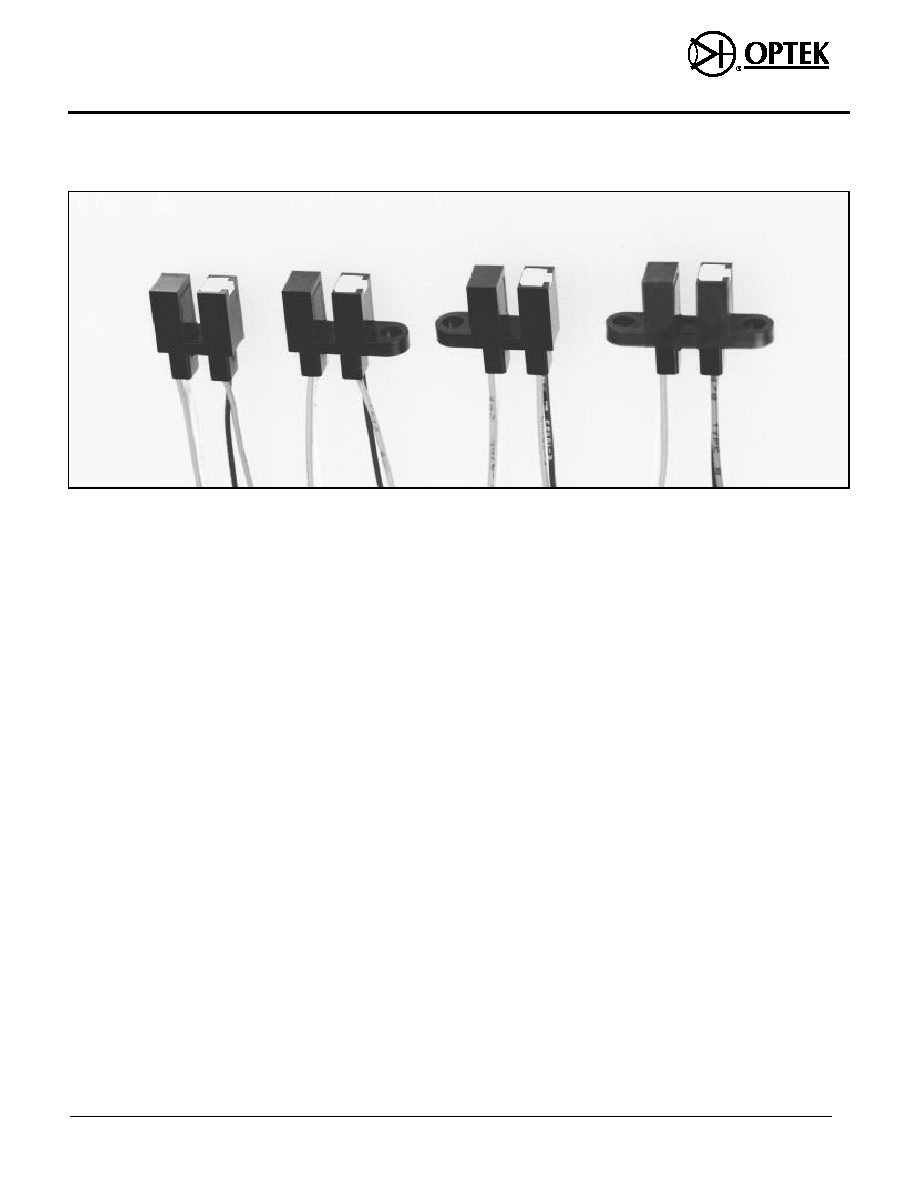
De scrip tion
The OPB380/390 series of slotted
switches provides the design engineer
with the flexibility of a custom device
from a standard product line. Building
from a standard housing with a 0.125"
(3.18 mm) wide slot, the user can specify
(1) electrical output parameters, (2)
mounting tab configuration, (3) discrete
shell material, and (4) aperture width.
All housings are an opaque grade of
injection-molded plastic to minimize the
assembly's sensitivity to ambient
radiation, both visible and near-infrared.
Discrete shells (exposed only on the
parallel faces inside the device throat)
are either IR transmissive plastic for
applications where aperture
contamination may occur or opaque
plastic with aperture openings for
maximum protection against ambient
light.
Re places/Up grades
OPB880/OPB890 Series
Ab so lute Maxi mum Rat ings (T
A
= 25
o
C un less oth er wise noted)
Stor age and Op er at ing Tem pera ture Range . . . . . . . . . . . . . . . . . -40
o
C to +80
o
C
(1)
In put Di ode
For ward DC Cur rent . . . . . . . . . . . . . . . . . . . . . . . . . . . . . . . . . . . . . . . . . . . . . 50 mA
Peak For ward Cur rent (1
µ
s pulse width, 300 pps) . . . . . . . . . . . . . . . . . . . . . . . 3.0 A
Re verse DC Volt age. . . . . . . . . . . . . . . . . . . . . . . . . . . . . . . . . . . . . . . . . . . . . . . 2.0 V
Power Dis si pa tion . . . . . . . . . . . . . . . . . . . . . . . . . . . . . . . . . . . . . . . . . . . . 100 mW
(1)
Out put Pho to tran sis tor
Collector- Emitter Volt age. . . . . . . . . . . . . . . . . . . . . . . . . . . . . . . . . . . . . . . . . . . . 30 V
Emitter- Collector Volt age . . . . . . . . . . . . . . . . . . . . . . . . . . . . . . . . . . . . . . . . . . . 5.0 V
Col lec tor DC Cur rent . . . . . . . . . . . . . . . . . . . . . . . . . . . . . . . . . . . . . . . . . . . . . 30 mA
Power Dis si pa tion . . . . . . . . . . . . . . . . . . . . . . . . . . . . . . . . . . . . . . . . . . . . 100 mW
(1)
Notes:
(1) Derate linearly 1.82 mW/
o
C above 25
o
C (Maximum storage and operating temperature is
limited by the temperature rating of the lead wires)
(2) All parameters tested using pulse technique.
(3) The OPB380/OPB390 wire terminations are 24" of 7 strand, 26 AWG, UL 1429 insulated wire
on each terminal. The devices incorporate a wire strain relief at the housing surface. The
insulation colors and functions are:
RED - IRED An ode
WHITE - Pho to tran sis tor Col lec tor
BLACK - IRED Cath ode
GREEN - Pho to tran sis tor Emit ter
Other wire lengths and/or col ors are avail able. Con tact your lo cal rep re sen ta tive or call the
fac tory.
Prod uct Bul le tin OPB380
August 1996
Slot ted Op ti cal Switches
Types OPB380, OPB390 Se ries
Op tek Tech nol ogy, Inc. 1215 W. Crosby Road Car roll ton, Texas 75006 (972) 323- 2200 Fax (972) 323- 2396
12-12
PART NUMBER GUIDE
OPB 3 X X X X X
Optek Assembly
Aperture Width In Front
of Sensor
5 = 0.050" 1 = 0.010"
Phototransistor Output
Aperture Width In Front
Family
of Emitter
5 = 0.050" 1= 0.010"
Discrete Shell Material
Mounting Configurations
Designation
8 - Base Mount IR Transmissive
T -Both Mounting Tabs
Plastic Discrete Shell
N - No Mounting Tabs
With Wire Termination
L - Single Mounting Tab
Emitter Side
9 - Base Mount Opaque
P - Single Mounting Tab
Plastic Discrete Shell
Phototransistor Side
With Wire Termination
Types OPB380, OPB390 Series
Optek reserves the right to make changes at any time in order to improve design and to supply the best product possible.
Op tek Tech nol ogy, Inc. 1215 W. Crosby Road Car roll ton, Texas 75006 (972) 323- 2200 Fax (972) 323- 2396
12-13
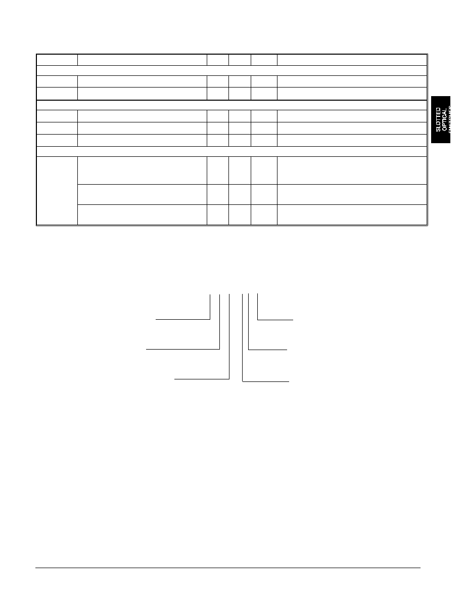
Elec tri cal Char ac ter is tics (T
A
= 25
o
C un less oth er wise noted)
SYM BOL
PA RAME TER
MIN MAX UNITS
TEST CON DI TIONS
In put Di ode
V
F
Forward Voltage
1.7
V
I
F
= 20 mA
I
R
Reverse Current
100
µ
A
V
R
= 2 V
Out put Pho to tran sis tor
V
(BR)CEO
Collector-Emitter Breakdown Voltage
30
V
I
C
= 1 mA
V
(BR)ECO
Emitter-Collector Breakdown Voltage
5.0
V
I
E
= 100
µ
A
I
CEO
Collector-Emitter Dark Curreent
100
nA
V
CE
= 10 V, I
F
= 0, E
e
= 0
Cou pled
I
C(ON)
On-State Collector Current
OPB380T, N, L, P55
OPB390T, N, L, P55
3.5
14.0
mA
V
CE
= 0.4 V, I
F
= 20 mA
OPB380T, N, L, P51
OPB390T, N, L, P51
2.5
10.0
mA
V
CE
= 0.4 V, I
F
= 20 mA
OPB380T, N, L, P11
OPB390T, N, L, P11
1.0
5.0
mA
V
CE
= 0.4 V, I
F
= 20 mA
Types OPB380, OPB390 Series
Op tek Tech nol ogy, Inc. 1215 W. Crosby Road Car roll ton, Texas 75006 (972) 323- 2200 Fax (972) 323- 2396
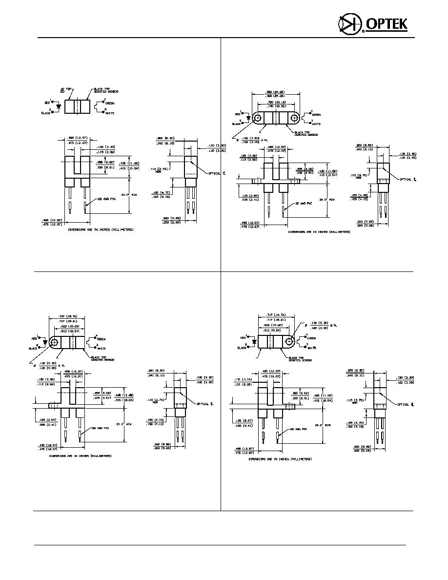
Package N
Package T
Package P
Package L
12-14
Notes:
(1) Ap er ture di men sions de pend ent on part number. See Part Num ber Guide.
GRAY/CLEAR TOP
DENOTES LED
GRAY/CLEAR TOP
GRAY/CLEAR TOP
DENOTES LED
GRAY/CLEAR TOP
DENOTES LED
Types OPB380, OPB390 Series
12-15
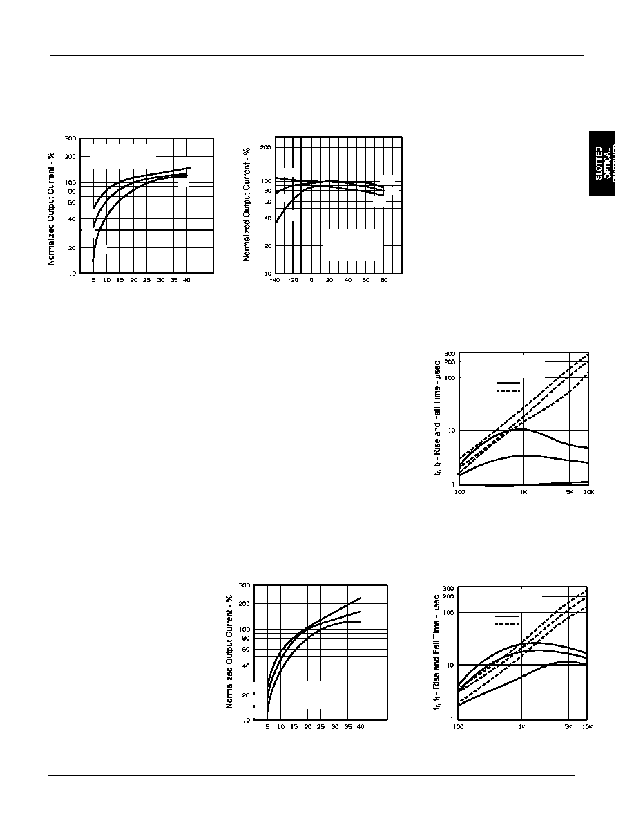
Typi cal Per form ance Curves
Normalized Output Current vs
Forward Current
I
F
- Forward Current - mA
Normalized Output Current vs
Ambient Temperature
T
A
- Ambient Temperature -
o
C
V
CE
= 0.4 V
I
F
= 20 mA
Normalized to
T
A
= 25
o
C
Normalized Output Current vs
Forward Current
I
F
- Forward Current - mA
V
CE
= 0.4 V
Normalized to
I
F
= 20 mA
Rise and Fall Time vs
Load Resistance
R
L
- Load Resistance -
I
F
= 20 mA (50% Duty
Cycle)
V
CE
= 0.4 V
Rise and Fall Time vs
Load Resistance
R
L
- Load Resistance -
I
F
= 20 mA (50% Duty
Cycle)
V
CE
= 0.4 V
V
CE
= 0.4 V
Normalized to
I
F
= 20 mA
+2
Typ
-2
+2
Typ
-2
Rise Time
Fall Time
All Part Numbers Ending in "1"
+2
Typ
-2
+2
Typ
-2
Rise Time
Fall Time
+2
Typ
-2
+2
Typ
Optek reserves the right to make changes at any time in order to improve the design and to supply the best product possible.
Op tek Tech nol ogy, Inc. 1215 W. Crosby Road Car roll ton, Texas 75006 (972) 323- 2200 Fax (972) 323- 2396
-2