 | –≠–ª–µ–∫—Ç—Ä–æ–Ω–Ω—ã–π –∫–æ–º–ø–æ–Ω–µ–Ω—Ç: OPB608A | –°–∫–∞—á–∞—Ç—å:  PDF PDF  ZIP ZIP |
Optek Technology
OPTEK Technology Inc.--
1645 Wallace Drive, Carrollton, Texas 75006
Phone: (800) 341-4747 FAX: (972) 323≠ 2396 sensors@optekinc.com www.optekinc.com
Reflective Object Sensor
OPB608A/B/C, OPB608R, OPB608V
∑
Phototransistor Output
∑
Unfocused for sensing diffuse surface
∑
Low Cost Plastic Housing
∑
Enhanced signal to noise ratio
∑
Reduced ambient light sensitivity
The OPB608 is a reflective switch that consist of an infrared emitting device (LED or VCSEL) and an NPN silicon phototransistor mounted
"side-by-side" on a parallel axis in a black opaque plastic housing. Both the emitting device and phototransistor are encapsulated in a visible
filtering epoxy except the OPB608R. The phototransistor responds to radiation from the emitter only when a reflective object passes within its
field of view. The phototransistor has enhanced low current roll off to improve the contrast ratio and immunity to background irradiance. The
LED versions are designed for near field applications with the VCSEL version being designed for longer distances.
The OPB608A/B/C devices are designed for applications with reflective distances between 0.050" and 0.375" and when the light pattern is not
to be seen by the human eye except for the OPB608R. By utilizing the night enhancement function of a camera, the near infrared light pattern
can be seen. This allows the user to see the pattern shining on the reflective object.
The OPB608R device is designed for applications with reflective distances between 0.050" and 0.300" and when the light pattern is to be seen
by the human eye. The efficiency of the sensor is lower for optical wavelengths in the visible range thus reducing the distance that can be
used.
The OPB608V device is designed for applications with reflective distances between 0.050" and 1.5" and when the light pattern is not to be seen
by the human eye. By utilizing the night enhancement function of a camera, the near infrared light pattern can be seen. This allows the user to
see the pattern shining on the reflective object.
Reflective distances are dependent upon the drive current for the light emitting device, the wavelength of the light source, and the type of re-
flective material, therefore each application should be checked for the ability to meet each application.
Optek reserves the right to make changes at any time in order to improve design and to supply the best product possible.
Issue A 06.04
A subsidiary of
TT electronics plc
Ordering Information
OPB608A--880nm LED, I
C(ON)
2.0 mA min.
OPB608B--880nm LED, I
C(ON)
1.0 mA min, 4.0 mA max.
OPB608C--880nm LED, I
C(ON)
0.5 mA min
OPB608R--660nm LED, I
C(ON)
1.0 mA min, 6.0 mA max.
OPB608V--850nm VCSEL, I
C(ON)
5.0 mA min.
Additional laser safety information can be found
on the Optek website. See application #221.
Classification is not marked on the device due to
space limitations. See package outline for
centerline of optical radiance. Operating de-
vices beyond maximum rating may cause de-
vices to exceed rated classification

Optek Technology
OPTEK Technology Inc.--
1645 Wallace Drive, Carrollton, Texas 75006
Phone: (800) 341-4747 FAX: (972) 323≠ 2396 sensors@optekinc.com www.optekinc.com
Absolute Maximum Ratings
T
A
= 25
o
C unless otherwise noted
Storage and Operating Temperature
-40∞ C to +85∞ C
Lead Soldering Temperature (1/16" (1.6mm) from case for 5 seconds with soldering iron)
260
∞ C
(1)
Infrared-LED (880nm)
(OPB608A, OPB608B, OPB608C)
Forward DC Current
50 mA
Power Dissipation
75 mW
(3)
Reverse DC voltage
2.0 V
Peak Forward Current (1µs pulse width, 300 pps)
3.0 A
Infrared-VCSEL (850nm)
(OPB608V)
Forward DC Current
30 mA
Reverse DC voltage
5.0 V
Power Dissipation
75 mW
(3)
Notes:
(1) RMA flux is recommended. Duration can be extended to 10 seconds maximum when flow soldering.
(2) Methanol or isopropanol are recommended as cleaning agents. The plastic housing is soluble in chlorinated hydrocarbons and keytones.
(3) Derate Linearly 1.6 mW/∞C above 25∞C.
Phototransistor
Collector-Emitter Voltage
30 V
Emitter Reverse Current
10 mA
Collector DC Current
25 mA
Power Dissipation
100 mW
(3)
Visible Red-LED (660nm)
(OPB608R)
Forward DC Current
50 mA
Reverse DC voltage
5.0 V
Power Dissipation
100 mW
(3)
Reflective Object Sensor
OPB608A, OPB608B, OPB608C, OPB608R, OPB608V
Issue A 06.04
Page 2 of 9

Optek Technology
Reflective Object Sensor
OPB608A, OPB608B, OPB608C, OPB608R, OPB608V
OPTEK Technology Inc.--
1645 Wallace Drive, Carrollton, Texas 75006
Phone: (800) 341-4747 FAX: (972) 323≠ 2396 sensors@optekinc.com www.optekinc.com
Electrical Characteristics
(T
A
= 25
∞C unless otherwise noted)
Issue A 06.04
Page 3 of 9
SYMBOL
PARAMETER
MIN
Typ. MAX UNITS
CONDITIONS
Infrared-LED (880nm)
V
F
Forward Voltage
--
1.7
V
I
F
= 20 mA
I
R
Reverse Current
--
100
µA
V
R
= 2.0 V
Visible Red-LED (650nm)
VF
Forward Voltage
--
1.9
2.5
V
I
F
= 20 mA
V
R
Reverse Voltage
5.0
V
I
R
= 10.0 µA
Infrared VCSEL (850)
VF
Forward Voltage
--
2.15
V
I
F
= 12 mA
I
R
Reverse Current
--
30
nA
V
R
= 5 V
I
TH
Threshold Current
2.0
5.5
mA
Beam Divergence
12
Deg.
I
F
= 12 mA
Phototransistor
V
BR
/
CEO
Collector Emitter Breakdown Voltage
30
--
V
I
C
= 100 µA
I
ECO
Emitter Collector Reverse Current
--
100
µA
V
EC
= 0.4 Volts
I
CEO
Collector Emitter Dark Current
--
100
nA
V
CE
= 5.0 V, Ee = 0.10 µW/cm
2
,
I
F
=0
I
C(ON)
On-State Collector Current
OPB608A
OPB608B
OPB608C
OPB608R
OPB608V
2.0
1.0
0.5
1.0
5.0
--
4.0
--
6.0
--
mA
mA
mA
mA
mA
V
CE
= 5.0 V, I
F
= 20 mA
d = 0.110 inch (2.79 mm)
(1)(2)
I
C(OFF)
Off-State Collector Current
--
100
nA
V
CE
= 5.0 V, I
F
= 20 mA
No reflective surface
Combined
NOTES:
(1) Distance from the measurement surface to reflective surface (see mechanical page outline).
(2) Measured using Eastman Kodak Gray card. The white side of the card uses as a 90% diffuse reflective surface. Reference Eastman
Kodak catalog # E152 7795
(3) All parameters are tested using pulse techniques.
Optek Technology
OPTEK Technology Inc.--
1645 Wallace Drive, Carrollton, Texas 75006
Phone: (800) 341-4747 FAX: (972) 323≠ 2396 sensors@optekinc.com www.optekinc.com
Reflective Object Sensor
OPB608A, OPB608B, OPB608C, OPB608R, OPB608V
Issue A 06.04
Page 4 of 9
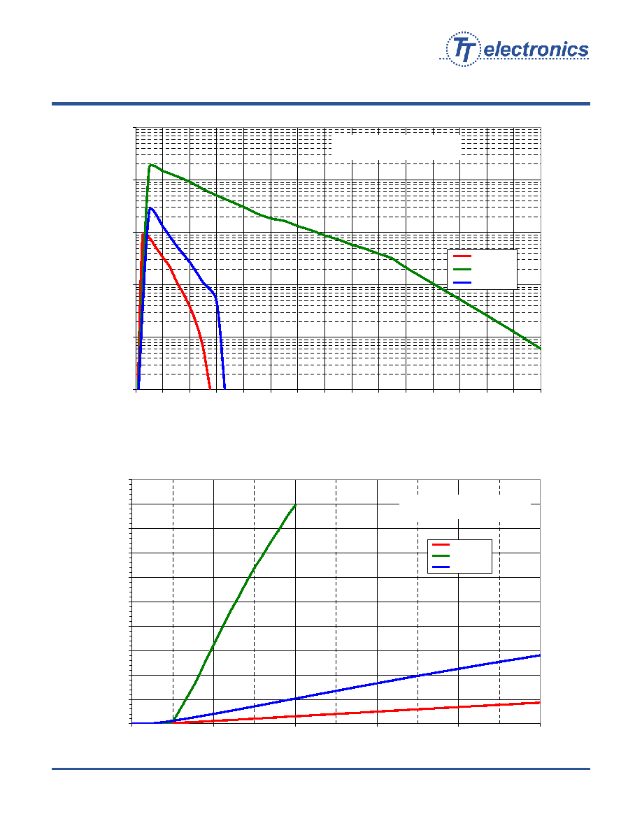
Collector Current vs Object Distance
0.001
0.010
0.100
1.000
10.000
100.000
0.00
0.10
0.20
0.30
0.40
0.50
0.60
0.70
0.80
0.90
1.00
1.10
1.20
1.30
1.40
1.50
Distance to Reflectave Surface - Inches
Ic - Typical Collector Current - mA
OPB608R
OPB608V
OPB608
Vce=5 Volts, I
F
= 20 mA
Standard Test Conditions
Collector Current vs Diode Forward Current
0
2
4
6
8
10
12
14
16
18
20
0
10
20
30
40
50
I
F
- Forward Current - mA
Ic - Typical Collector Current - mA
OPB608R
OPB608V
OPB608
Vce = 5 Volts
Standard Test Conditions
Optek Technology
OPTEK Technology Inc.--
1645 Wallace Drive, Carrollton, Texas 75006
Phone: (800) 341-4747 FAX: (972) 323≠ 2396 sensors@optekinc.com www.optekinc.com
Reflective Object Sensor
OPB608A, OPB608B, OPB608C, OPB608R, OPB608V
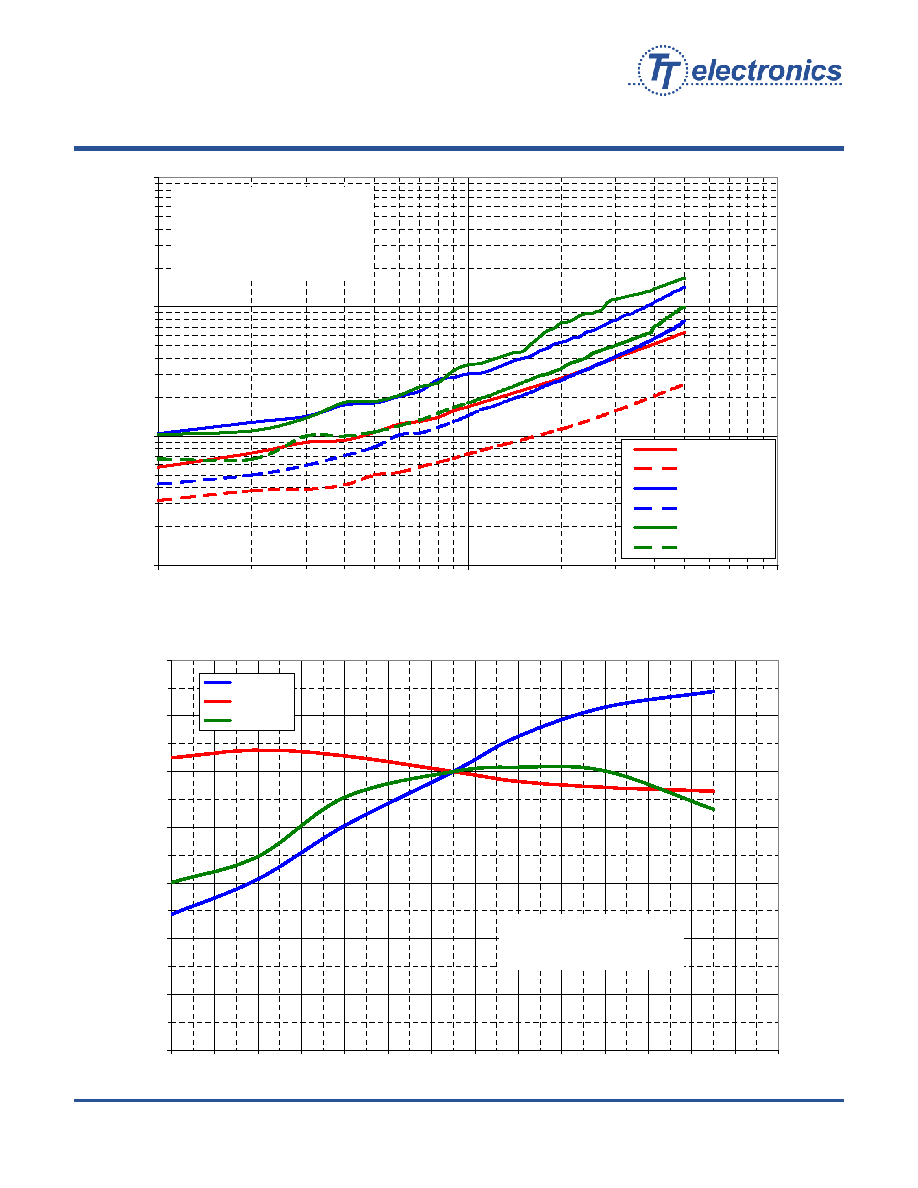
Rise and Fall vs Load Resistance
1
10
100
1000
100
1000
10000
RL - Load resistance - Ohms
Tr,Tf - Switching Speed - usec
OPB608R - Tr
OPB608R - Tf
OPB608 - Tr
OPB608 - Tf
OPB608V - Tr
OPB608V - Tf
10% Duty Cycle
1 ms Pulse Width
Vce = 5 Volts
Standard Test Conditons
Normalized Collector Current vs Ambient Temperature
0%
20%
40%
60%
80%
100%
120%
140%
-40
-30
-20
-10
0
10
20
30
40
50
60
70
80
90
100
Ta - Ambient Temperature - ∞C
Normalized Collector Current - %
OPB608R
OPB608
OPB608V
Standard Test Conditions
Vce=5 Volts
Normalized to Ta=25 ∞C
Issue A 06.04
Page 5 of 9
Optek Technology
OPTEK Technology Inc.--
1645 Wallace Drive, Carrollton, Texas 75006
Phone: (800) 341-4747 FAX: (972) 323≠ 2396 sensors@optekinc.com www.optekinc.com
Reflective Object Sensor
OPB608A, OPB608B, OPB608C, OPB608R, OPB608V
Issue A 06.04
Page 6 of 9
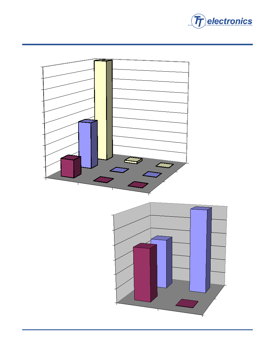
OPB608V
OPB608
OPB608R
Copier Black
Inkjet Black
Laserjet Black
0
10
20
30
40
50
60
70
80
90
100
OPB608
OPB608R
Black Thermal Paper
Thermal Paper
0
200
400
600
800
1000
1200
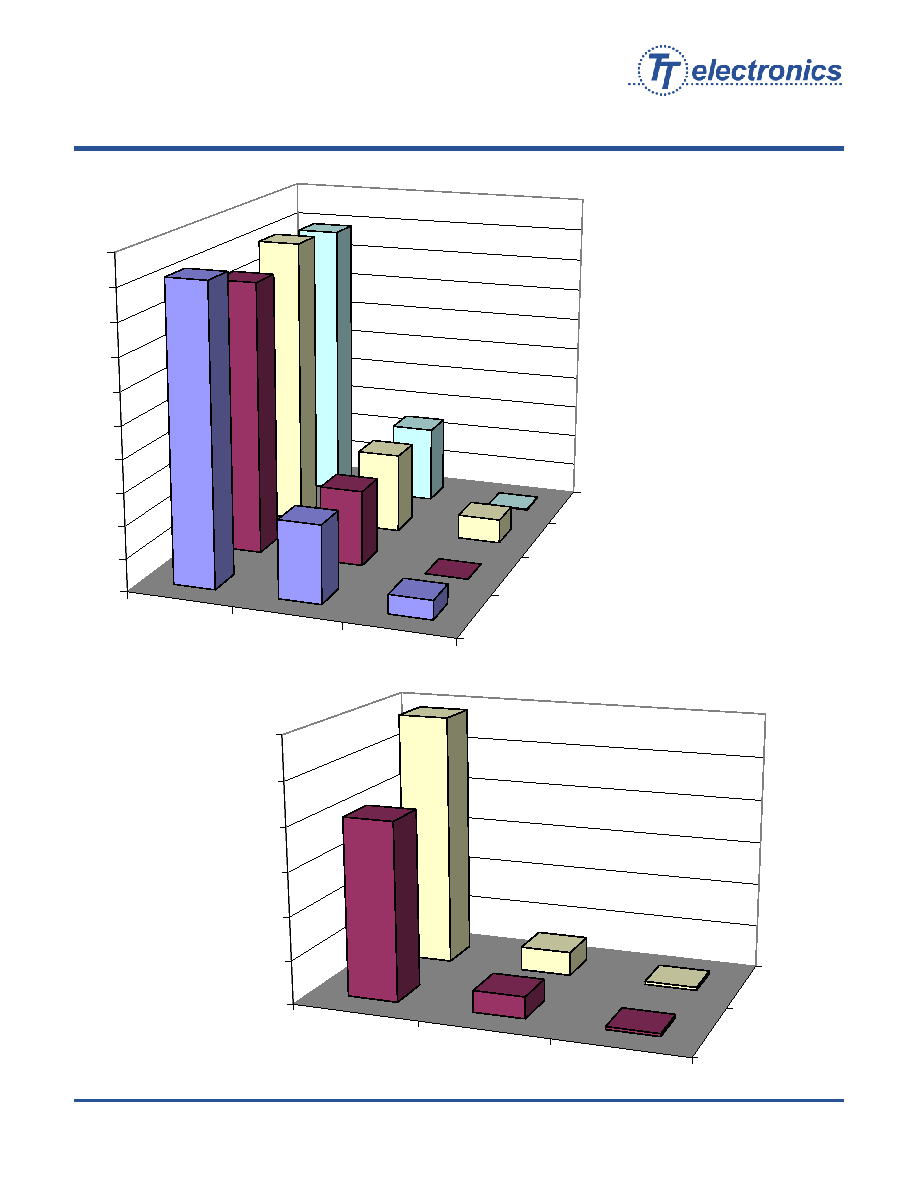
Reletive Response

Optek Technology
OPTEK Technology Inc.--
1645 Wallace Drive, Carrollton, Texas 75006
Phone: (800) 341-4747 FAX: (972) 323≠ 2396 sensors@optekinc.com www.optekinc.com
Reflective Object Sensor
OPB608A, OPB608B, OPB608C, OPB608R, OPB608V
Issue A 06.04
Page 7 of 9
Reletive Response
OPB608V
OPB608
OPB608R
Gray 18%
White 90%
0
500
1000
1500
2000
2500
3000
3500
4000
4500
5000
OPB608V
OPB608
OPB608R
Copier 20% Black
Laser 20% Black
Laserjet 20% Black
Inkjet 20% Black
0
1000
2000
3000
4000
5000
6000
Optek Technology
OPTEK Technology Inc.--
1645 Wallace Drive, Carrollton, Texas 75006
Phone: (800) 341-4747 FAX: (972) 323≠ 2396 sensors@optekinc.com www.optekinc.com
Reflective Object Sensor
OPB608A, OPB608B, OPB608C, OPB608R, OPB608V
Issue A 06.04
Page 8 of 9
Reletive Response
OPB608V
OPB608
OPB608R
Inkjet Magenta
Inkjet Cyan
Inkjet Yellow
Inkjet Green
0
500
1000
1500
2000
2500
3000
3500
4000
4500
5000
OPB608V
OPB608
OPB608R
White Plastic
Silver Tape
0
500
1000
1500
2000
2500
3000
Optek Technology
OPTEK Technology Inc.--
1645 Wallace Drive, Carrollton, Texas 75006
Phone: (800) 341-4747 FAX: (972) 323≠ 2396 sensors@optekinc.com www.optekinc.com
Reflective Object Sensor
OPB608A, OPB608B, OPB608C, OPB608R, OPB608V
Issue A 06.04
Page 9 of 9
Ordering Information
OPB608A--880nm LED, I
C(ON)
2.0 mA min.
OPB608B--880nm LED, I
C(ON)
1.0 mA min, 4.0 mA max.
OPB608C--880nm LED, I
C(ON)
1.0 mA min
OPB608R--650nm LED, I
C(ON)
0.5 mA min, 6.0 mA max.
OPB608V--850nm VCSEL, I
C(ON)
5.0 mA min.
Notes:
(1) RMA flux is recommended. Duration can be extended to 10 seconds maximum when flow soldering.
(2) Methanol or isopropanol are recommended as cleaning agents. The plastic housing is soluble in chlorinated hydrocarbons and keytones.
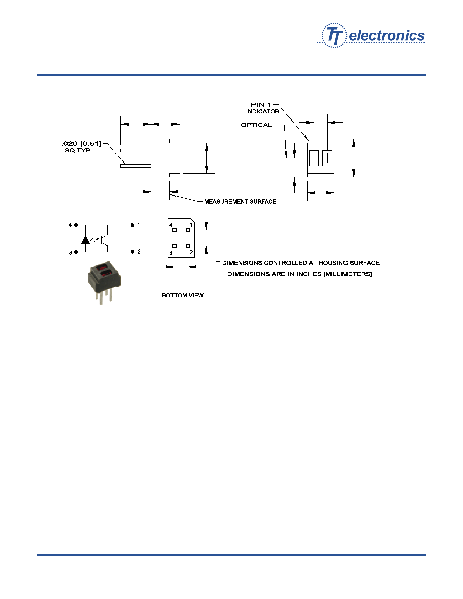
0.100 [2.54]
0.087 [2.21]
0.120 [3.05]
0.200 [5.08]
0.185 [4.70]
0.200 [5.08]
0.125 [3.18]
0.173 [4.39]
0.250 [6.35]
0.087 [2.21]
CL