Optek Technology, Inc.
sensor@optekinc.com
Carrollton, Texas 75006
(972) 323-2200
www.optekinc.com
May 2003
Issue 1.0
Page 1
850nm Fiber Optic
Receiver Module
in Dual-in-Line Package
Technical Data
OPF2416, OPF2416T, OPF2416TC
Features
x
850 nm wavelength
x
Link distance up to 2 km
x
Data rates up to 155 Mbps
x
Wide operating temperature range
x
Optimized for use with 62.5/125µm and
50/125µm Multimode Fiber
x
ST
Æ
Receptacle
x
Wave Solderable Dual-in-Line Package
Description
The OPF0400 series is a cost effective solution for 850 nm
fiber optic link designs. The transmitter and receiver pair are
designed for use with multimode optical fiber with either
50/125µm or 62.5/125µm diameters. This fiber optic pair is
housed in a space saving, auto-insertable package that is
compatible with most wave solder processes.
Receiver
OPF2416 is a low cost solution for high speed, fiber optic
communications designs. The internal lensing of this re-
ceiver's design allows optimal response from fiber sizes of
100µm and below.
The receiver is comprised of a high speed, low noise, photodi-
ode coupled to a transimpedance amplifier (TIA). The photo-
diode/TIA combination produces an output voltage that is pro-
portional in the input light amplitude. This hybrid approach
solves many of the problems of high speed data link designs
by placing the photodiode close to the TIA. The amplification
of the TIA makes the output much less susceptible to EMI.
The output of the OPF2416 is an analog, low impedance,
emitter follower voltage source. Subsequent circuitry can
utilized to convert the analog voltage to ECL/TTL for digital
data rates up to 155 Mbps.
The OPF2416 is available with either standard or threaded
panel mount ST
Æ
receptacles. The threaded version is also
available in conductive plastic. Refer to the part number
guide for more details.
ST
Æ
is a registered trademark of OFS Fitel USA.
Storage Temperature Range
-55 to +85 ∞C
Operating Temperature Range
-40 to +85 ∞C
Lead Soldering Temperature
260 ∞C for 10 Seconds
Supply Voltage Range
-0.5 to 6.0 V
Output Current
25mA
Output Pin Voltage
-0.5 V
Absolute Maximum Ratings
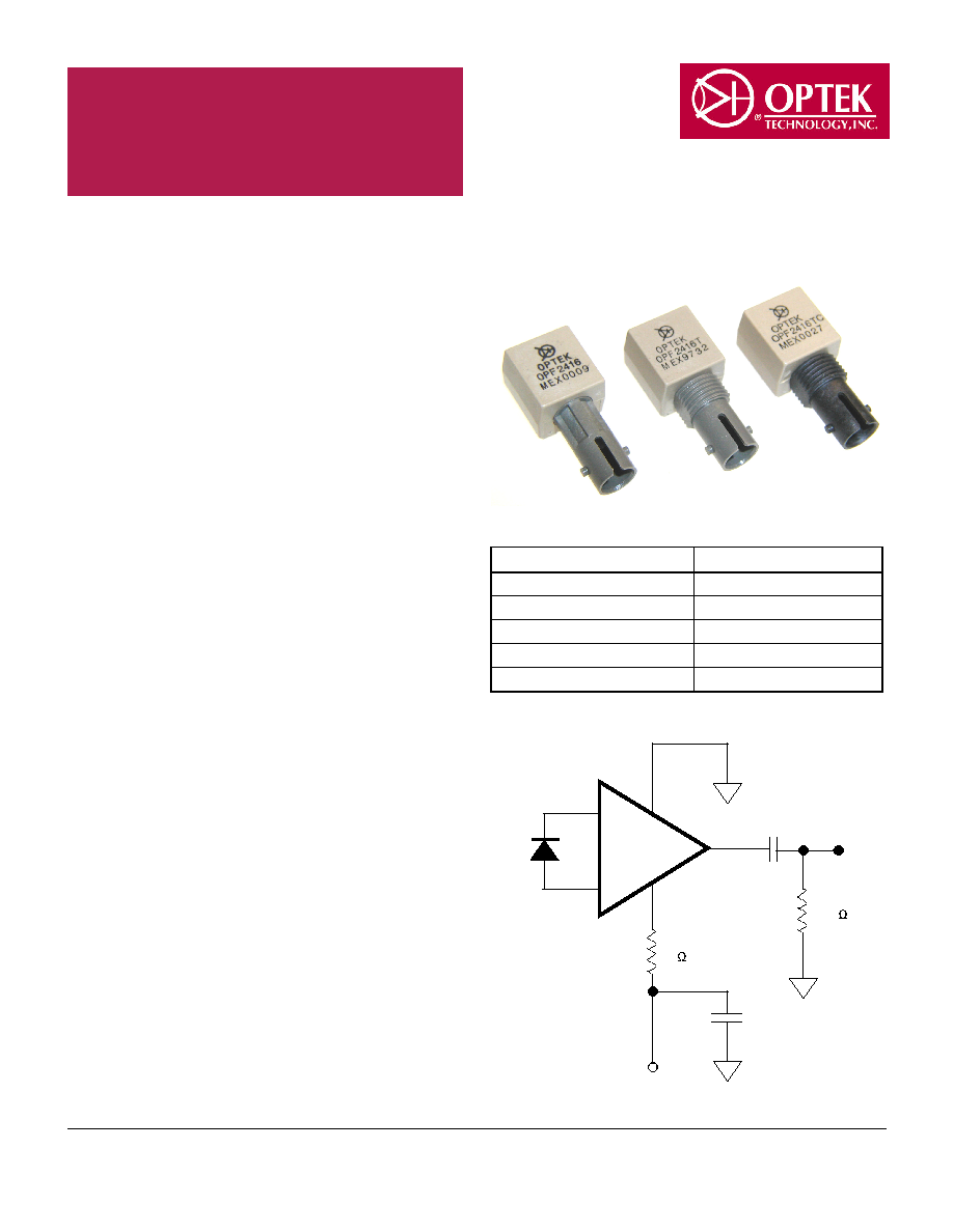
OPF2416
10
511
0.1µF
6
3,7
2
-5.2V
0.1µF
Recommended AC coupled receiver circuit
Optek Technology, Inc.
sensor@optekinc.com
Carrollton, Texas 75006
(972) 323-2200
www.optekinc.com
May 2003
Issue 1.0
Page 2
OPF0400 Series Technical Data
Data Rate (MBd)
Distance (m)
Transmitter
Receiver
Fiber Size (µm)
5
1500
OPF1414
OPF2412
200 HCS
5
2000
OPF1414
OPF2412
62.5/125
20
2500
OPF1414
OPF2416
62.5/125
30
2000
OPF1414
OPF2416
62.5/125
50
1500
OPF1414
OPF2416
62.5/125
155
300
OPF1414
OPF2418
62.5/125
125
500
OPF1414
OPF2416
62.5/125
Link Selection Guide
Part Number Guide
Distances listed in this guide are for reference only. A link budget should be completed for the specific application to determine actual
distance.
OPF X 4 1 X yy
Type
Options
1 - Transmitter
T - Threaded Receptacle
2 - Receiver
C - Conductive Receiver Receptacle
Family
Transmitter
4 - 850nm Transmitters
4 - High Optical Power
and Receivers
Connector
Receiver
1 - ST Receptacle
2 - 5MBd, TTL Output
6 - 125Mhz, Analog Output
8 - 155Mhz, Analog Output
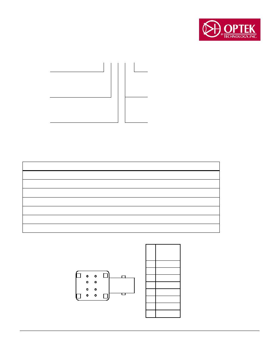
1
2
3
4
8
7
6
5
Pin
OPF2416
OPF2416T
OPF2416TC
1 N.C.
2 Signal
3 V
EE
4 N.C.
5 N.C.
6 V
CC
7 V
EE
8 N.C.
Bottom View
Optek reserves the right to make changes at any time, without notice, in order to improve design and provide the be product possible.
Optek Technology, Inc.
sensor@optekinc.com
Carrollton, Texas 75006
(972) 323-2200
www.optekinc.com
May 2003
Issue 1.0
Page 3
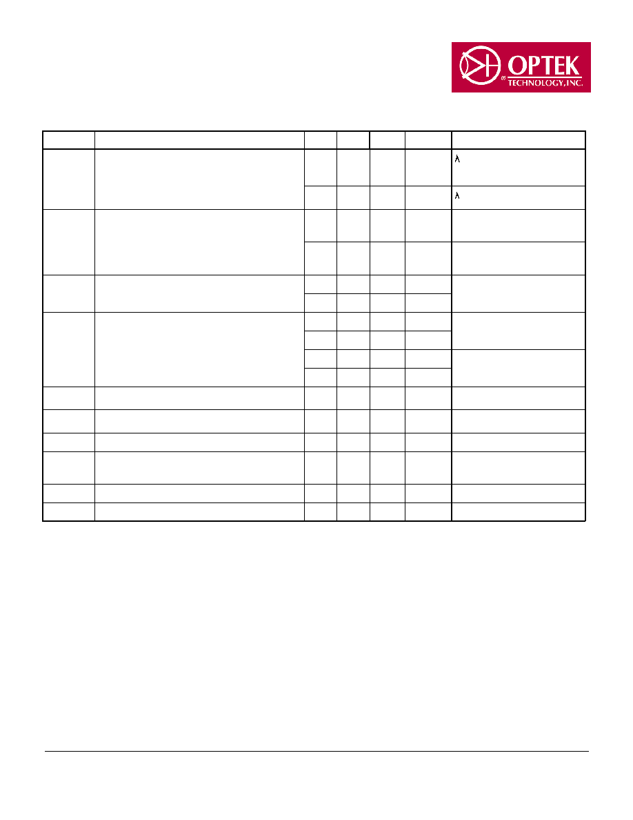
SYMBOL
PARAMETER
MIN TYP MAX UNITS
TEST CONDITION
R
P
Responsivity
5.3
7.0
9.6
mV/µW
P
=850 nm, 50 MHz
T
A
=25
°
C
4.5
11.5 mV/µW
P
=850 nm, 50 MHz
V
NO
RMS Output Noise Voltage
0.40 0.59
mV
75 MHz Bandwidth
P
R
= 0 µW
0.7
mV
Unfiltered Bandwidth
P
R
= 0 µW
P
N
RMS Equivalent Optical Noise Input Power
-43.0 -41.4
dBm
f =100 MHz
P
R
= 0 µW
0.050 0.065
µW
P
R
Peak Received Optical Power
-7.6
dBm
T
A
=25
°
C
175
µW
-8.2
dBm
150
µW
V
O
Output Voltage
-4.2 -3.1
-2.4
V
P
R
= 0 µW
I
CC
Supply Current
9
15
mA
R
L
=
f
BW
Bandwidth
125
MHz
-3 dB electrical
t
r
, t
f
Rise and Fall Time
3.3
6.3
ns
f =50 MHz
P
R
= -10 dBm, peak
PWD
Pulse Width Distortion
0.4
2.5
ns
P
R
= -10 dBm, peak
PSRR Power Supply Rejection Ratio
20
dB
10MHz
OPF2416 Receiver Electrical/Optical and Dynamic Characteristics
-5.45V
d
V
CC
d
-4.75, Operating Temperature Range ≠40 to 85∫C unless otherwise noted
OPF2416 Technical Data
Optek reserves the right to make changes at any time, without notice, in order to improve design and provide the be product possible.
