Optek Technology, Inc.
Carrollton, Texas 75006
(972) 323-2200
sensor@optekinc.com
www.optekinc.com
Page 1 of 4
July 2003
Issue 3.1
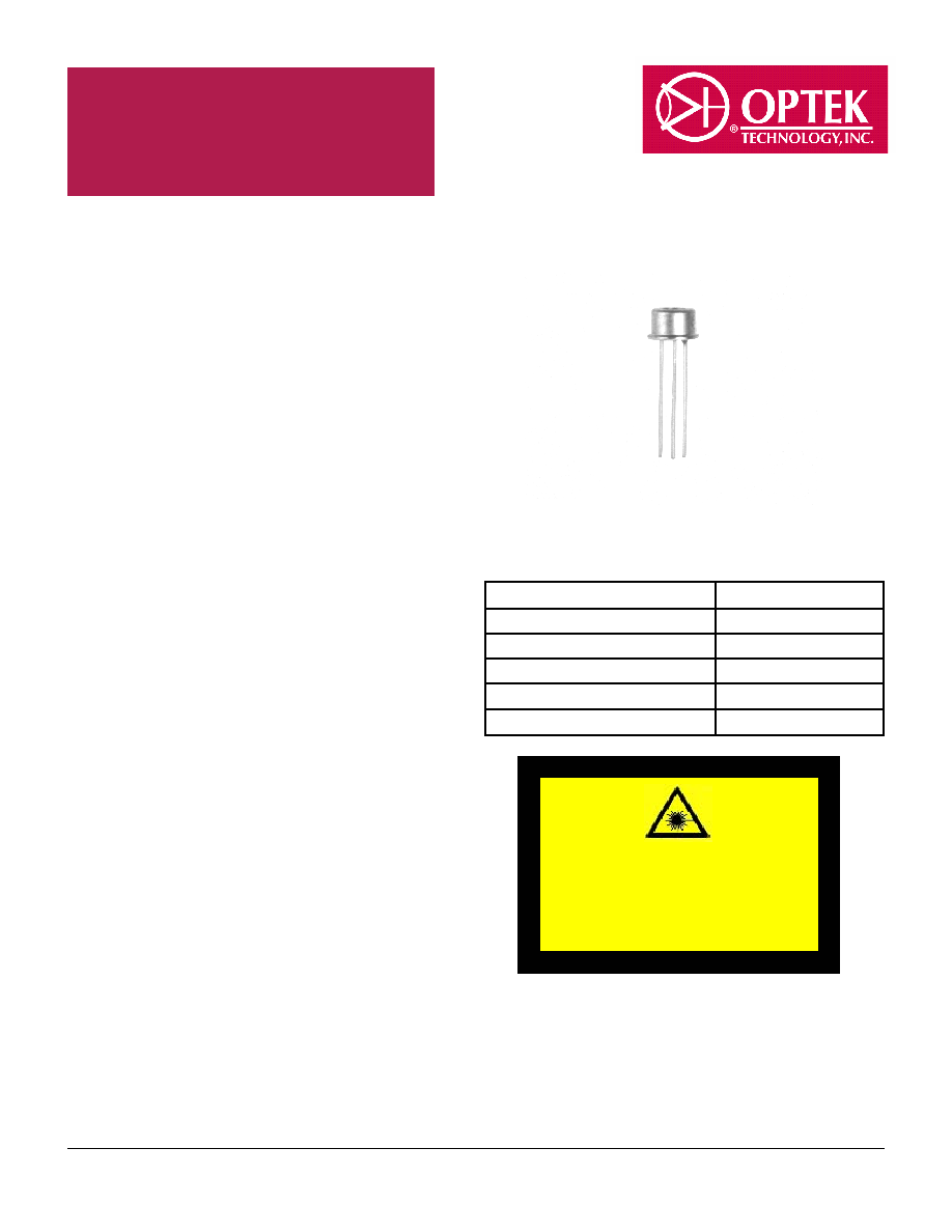
Vertical Cavity Surface
Emitting Laser in TO-46
Package
Description
The OPV210 is a high performance 850nm VCSEL
packaged for high speed communication links. OPV210
combines all the performance advantages of a VCSEL
with the addition of a power monitor diode for precise
control of optical power.
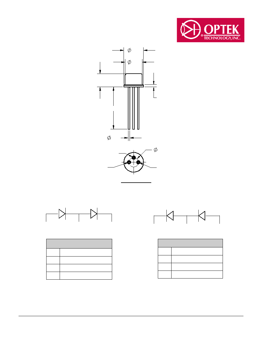
The OPV210Y is identical electrically and optically and
differs only in pin out. Refer to mechanical drawings for
details.
This product's combination of features including high
speed, high output power and concentric beam make it
an ideal transmitter for integration into all types of data
communications equipment.
Applications include:
Fibre Channel
Gigabit Ethernet
ATM
VSR (Very Short Reach)
Intra-system links
Optical backplane interconnects
.
Storage Temperature
-40∞ C to +125∞ C
Operating Temperature
-40∞ C to +85∞ C
Soldering Lead Temperature
260∞ C for 10 Seconds
Maximum Forward Peak Current
30 mA
Maximum Reverse Voltage
5 V
Max. Continuous Optical Power at 70∞C
1.1 mW
Absolute Maximum Ratings
(T
A
= 25∞ C unless otherwise noted)
Features
∑
850nm VCSEL Technology
∑
High thermal stability
∑
Low drive current/high output density
∑
Narrow and concentric beam angle
∑
Up to 1.25 Gbps
∑
Recommended for multimode fiber applications
∑
Flat Window
∑
Pin out and attenuation options available on
request
∑
Burned in for communication level reliability
This product is classified as 1M per EN/IEC60825-1/
A2:2001. The output from class 1M products must
not be viewed directly using optical magnifiers.
Additional laser safety information can be found on
the Optek website. See application bulletin #221.
850nm 0.7mW

Optek Technology, Inc.
Carrollton, Texas 75006
(972) 323-2200
sensor@optekinc.com
www.optekinc.com
Page 2 of 4
July 2003
Issue 3.1
OPV210, OPV210Y Technical Data
NOTES:
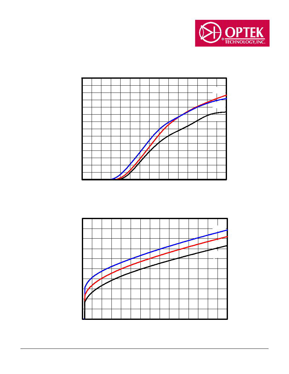
(1) Threshold Current is based on the two line intersection method specified in Telcordia GR-468-Core. Line 1 from 6 mA to 8 mA. Line 2 from 0
mA to 2 mA.
(2) Series Resistance is the slope of the Voltage-Current line from 8 to 12 mA.
(3) Slope efficiency, is the slope of the best fit LI line from 8 mA 12 mA.
(4) Using data points taken for slope efficiency above, delta L/delta I shall be calculated for each adjacent pair of 0.5 mA points. The minimum
shall be 0.0. (No negative values permitted).
Electrical/Optical Characteristics
(at 25
C unless otherwise specified)
Optek reserves the right to make changes at any time in order to improve design and to supply the best product possible.
SYMBOL
PARAMETER
MIN TYP MAX UNITS
TEST CONDITION
P
OT
Power Out Total
1.4
4.5
mW
I
F
= 12 mA
I
TH
Threshold Current
2.0
5.5
mA
Note1
V
F
Forward Voltage
2.15
V
I
F
= 12 mA
I
R
Reverse Current, VCSEL
30
nA
V
R
= 5 V
R
S
Series Resistance
14
40
ohms
Note 2
Slope Efficiency
0.17
mW/mA Note 3
Linearity
0.0
Note 4
I
RPD
Reverse Current, photo diode
30
nA
I
F
= 0 mA, V
R
= 5 V
I
M
Monitor Current
30
µ
A
I
F
= 12 mA, V
R
= 5 V
Wavelength
830
850
860
nm
Optical Bandwidth
0.85
nm
Beam Divergence
12
Degree I
F
= 12 mA
t
r
,
t
f
Rise and Fall Time
200
ps
20% to 80%
N
RI
Relative Intensity Noise
-123
db/Hz
l
TH
/
T
Temp Coefficient of Threshold Current
±1.5
mA
0∞ - 70∞ C, Note 1
/
T
Temp Coefficient of Wavelength
0.06
%/∞C
0∞ - 70∞ C, I
F
= 12 mA
V
F
/
T
Temperature Coefficient for VF
-2.5
mV/∞C 0∞ - 70∞ C, I
F
= 12 mA
/
T
Temperature Coefficient for Efficiency
-0.4
%/C
0∞ - 70∞ C, Note 3