Applications
∑
Non-contact position sensing
∑
Photoelectric sensors
∑
Optical encoders
∑
Light curtains
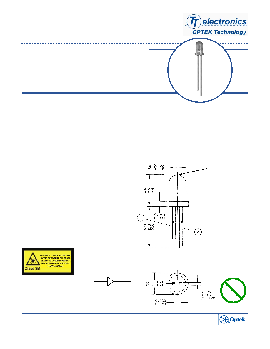
Vertical Cavity Surface Emitting
Laser in T-1 Package
OPV332
∑
850nm VCSEL technology
∑
High thermal stability
∑
Low drive current
∑
High output power
∑
Narrow Beam Angle
The OPV332 is a Vertical Cavity Surface Emitting Laser (VCSEL) packaged in a dome lens T-1 package.
VCSELs offer many advantages in sensing applications when compared to infrared LEDs. These devices require
substantially lower drive currents to obtain the same amount of output power as LEDs. This feature allows
VCSELs to be used in low power consumption applications such as battery operated equipment.
The dome lens packaging creates a narrow 4 degree beam angle from the device. Long distance applications
may benefit from this feature as secondary optics may be eliminated, reducing total system cost. The OPV332 is
optically and spectrally compatible with Optek's standard detector products such as the OP500 series phototran-
sistors, OP530 series photodarlingtons and the OP900 series photodiodes.
Optek reserves the right to make changes at any time in order to improve design and to supply the best product possible.
OPTEK Technology Inc.-- 1645 Wallace Drive, Carrollton, Texas 75006
Phone: (800) 341-4747 FAX: (972) 323≠ 2396 sensors@optekinc.com www.optekinc.com
A subsidiary of
TT electronics plc
Additional laser safety information can
be found on the Optek website. See
application bulletin #221.
Classification is not marked on the
device due to space limitations. See
package outline for centerline of opti-
cal radiance. Operating devices be-
yond maximum rating may result in
hazardous radiation exposure
.
1
2
VCSEL
Emission
Surface
Pb
LEAD FREE

VCSEL in T-1 Package
OPV332
OPTEK Technology Inc.-- 1645 Wallace Drive, Carrollton, Texas 75006
Phone: (800) 341-4747 FAX: (972) 323≠ 2396 sensors@optekinc.com www.optekinc.com
Electrical Characteristics
(T
A
= 25
∞
C unless otherwise noted)
Absolute Maximum Ratings
T
A
= 25
o
C unless otherwise noted
Storage Temperature Range
-40
∞ to
+100
∞
C
Operating Temperature Range
-40
∞ to
+85
∞
C
Lead Soldering Temperature [1/16 inch (1.6mm) from case for 5 sec with soldering iron]
260
∞
C
(1)
Maximum Forward Peak Current
20 mA
Maximum Reverse Voltage
5 V
NOTES:
(1) RMA flux is recommended. Solder dwell time can be increased to 10 seconds when flow soldering.
(2) Threshold Current is based on the two line intersection method specified in Telcordia GR-468-Core. Line 1 from 4 mA to 6 mA. Line 2 from 0 mA to 0.5 mA.
(3) Series Resistance is the slope of the Voltage-Current line from 5 to 8 mA.
(4) Slope efficiency, is the slope of the best fit LI line from 5 mA to 8 mA with 0.25mA test intervals.
SYMBOL
PARAMETER
MIN
TYP
MAX
UNITS
CONDITIONS
P
OT
Total Power Out
1.5
mW
I
F
= 7 mA
I
TH
Threshold Current
3.0
mA
Note 2
V
F
Forward Voltage
2.2
V
I
F
= 7 mA
I
R
Reverse Current
100
nA
V
R
= 5 V
R
S
Series Resistance
20
55
ohms
Note 3
Slope Efficiency
0.28
mW/mA
Note 4
Wavelength
830
860
nm
Optical Bandwidth
0.85
nm
Beam Divergence
4
Degrees
/
T
Temp Coefficient of Slope Efficiency
-0.50
%/
∞
C
(0
∞
- 70
∞
C), Note 4
/
T
Temp Coefficient of Wavelength
0.06
nm/
∞
C
(0
∞
- 70
∞
C)
l
TH
/
T
Temp Coefficient of Threshold Current
±1.0
mA
(0
∞
- 70
∞
C), Note 2
V
F
/
T
Temp Coefficient for Forward Voltage
-2.5
mV/
∞
C
(0
∞
- 70
∞
C)
Issue 1.1 05.05
Page 2 of 2
Typical Angular Output
0
0%
20%
40%
60%
100%
Angular Displacement--Degrees
Relativ
e
Output
60 90
Normalized Output Power vs.
Forward Current
0
2 4 6 8 10
12
Forward Current--mA
200%
100%
0%
Nor
m
alized Output Po
w
e
r
Normalized at 7mA, 25
∞
C
30
60
90 30
80%