
Issue 1.0 0505
Page 1
OPTEK Technology Inc. --
1645 Wallace Drive, Carrollton, Texas 75006
Phone: (972) 323-2200 or (800) 341-4747 FAX: (972) 323-2396 visibleLED@optekinc.com www.optekinc.com
1 ANODE 2 CATHODE
High-Intensity Yellow LED in Plastic
T-1
æ
Package
OVLGY0CxB9
x
Narrow Beam Angle
x
High Luminous Intensity
x
Water Clear Plastic Package
x
Yellow (589nm)
The OVLGY0CxB9 is a high intensity AlInGaP LED mounted in a clear plastic T-1æ package. The device incorpo-
rates an integral molded lens that enables a narrow beam angle and provides an even emission pattern. Designed
to produce light over a wide range of drive currents, this LED is useful in applications requiring higher on-axis
brightness than that achievable with standard lamps.
Applications
x
Indoor/Outdoor Applications
x
Message Boards
x
Store Front Signage
x
Indicators
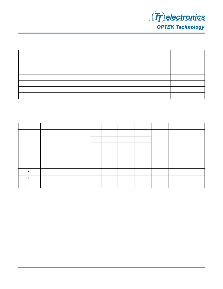
Product Photo Here
Part Number
Material
Emitted Color
Intensity Typ. mcd
Lens Color
OVLGY0C6B9
AlInGaP
Yellow
10000
OVLGY0C7B9
12500
OVLGY0C8B9
16000
Water Clear
OVLGY0C9B9
20000
OPTEK reserves the right to make changes at any time in order to improve design and to supply the best product possible.
RoHS
Issue 1.0 0505
Page 2
OPTEK Technology Inc. --
1645 Wallace Drive, Carrollton, Texas 75006
Phone: (972) 323-2200 or (800) 341-4747 FAX: (972) 323-2396 visibleLED@optekinc.com www.optekinc.com
T-1
æ
High-Intensity Yellow LED
OVLGY0CxB9
Absolute Maximum Ratings
T
A
= 25
o
C unless otherwise noted
Storage Temperature Range
-40 ~ +100 ∞C
Operating Temperature Range
-40 ~ +85 ∞C
Reverse Voltage
5 V
Continuous Forward Current
2
50 mA
Peak Forward Current (10% Duty Cycle, 1KHz)
100 mA
Power Dissipation
120 mW
2000 V
Electrostatic Discharge
Lead Soldering Temperature (3mm from the base of the epoxy bulb)
1
260 ∞C
Note:
1. Solder time less than 5 seconds at temperature extreme.
Electrical Characteristics
T
A
= 25
o
C unless otherwise noted
SYMBOL
PARAMETER
MIN
TYP
MAX
UNITS
CONDITIONS
I
v
Luminous Intensity
x = 6
6300
10000
----
mcd
I
F
= 20mA
8
10000
16000
----
9
12500
20000
----
V
F
Forward Voltage
----
2.0
2.4
V
I
F
= 20mA
I
R
Reverse Current
----
----
10
µA
V
R
= 5V
P
Peak Wavelength
----
591
----
nm
I
F
= 20mA
D
Dominant Wavelength
----
589
----
nm
I
F
= 20mA
2 ΩH-H
50% Power Angle
----
6
----
deg
I
F
= 20mA
7
8000
12500
----
Issue 1.0 0505
Page 3
OPTEK Technology Inc. --
1645 Wallace Drive, Carrollton, Texas 75006
Phone: (972) 323-2200 or (800) 341-4747 FAX: (972) 323-2396 visibleLED@optekinc.com www.optekinc.com
T-1
æ
High-Intensity Yellow LED
OVLGY0CxB9
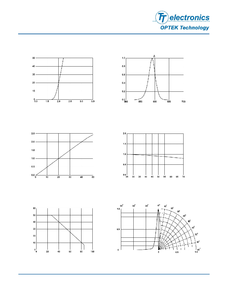
Typical Electro-Optical Characteristics Curves
Relative Luminous Intensity vs. Wavelength
%
mA
Half Power WL = 15nm
Relative Luminous Intensity vs. Ambient
Temperature
%
∞C
Forward Current vs. Forward Voltage
V
mA
Relative Luminous Intensity vs. Forward Current
mA
%
Forward Current vs. Ambient Temperature
∞C
mA
Relative Intensity vs. Radiation Angle
%
Issue 1.0 0505
Page 4
OPTEK Technology Inc. --
1645 Wallace Drive, Carrollton, Texas 75006
Phone: (972) 323-2200 or (800) 341-4747 FAX: (972) 323-2396 visibleLED@optekinc.com www.optekinc.com
Issue
Change Description
Approval
Date
1.0
Initial Release
J. Haynie
6/7/05
T-1
æ
High-Intensity Yellow LED
OVLGY0CxB9