Issue 1.0 0505
Page 1
OPTEK Technology Inc. --
1645 Wallace Drive, Carrollton, Texas 75006
Phone: (972) 323-2200 or (800) 341-4747 FAX: (972) 323-2396 visibleLED@optekinc.com www.optekinc.com
OVLKGGT6
x
High luminous intensity
x
Defined spatial radiation
x
Multiple viewing angles
x
UV-resistant epoxy
x
Precision optical performance
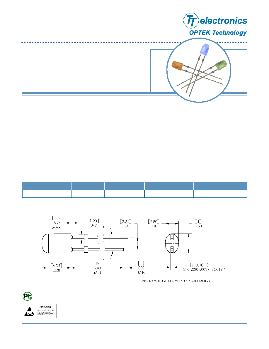
The OVLKGGT6 is designed for superior performance in outdoor environments. Its radiation pattern matches blue
(OVLKBGT6) and red-orange (OVLKQGT6) devices in identical packages to create LED pixels for full-color video
screens.
Applications
x
Variable Message Signs
x
Indoor/Outdoor Advertising Signage
x
Traffic and Highway Signs
x
Full-Color Video Signs
Part Number
Material
Emitted Color
Intensity Typ. mcd
OVLKGGT6
InGaN
Green
1100
Lens Color
Green Diffused
Data is subject to change without prior notice.
Oval Green LED Lamp (3mm)
1 ANODE 2 CATHODE
RoHS
Issue 1.0 0505
Page 2
OPTEK Technology Inc. --
1645 Wallace Drive, Carrollton, Texas 75006
Phone: (972) 323-2200 or (800) 341-4747 FAX: (972) 323-2396 visibleLED@optekinc.com www.optekinc.com
Oval Green LED Lamp (3mm)
OVLKGGT6
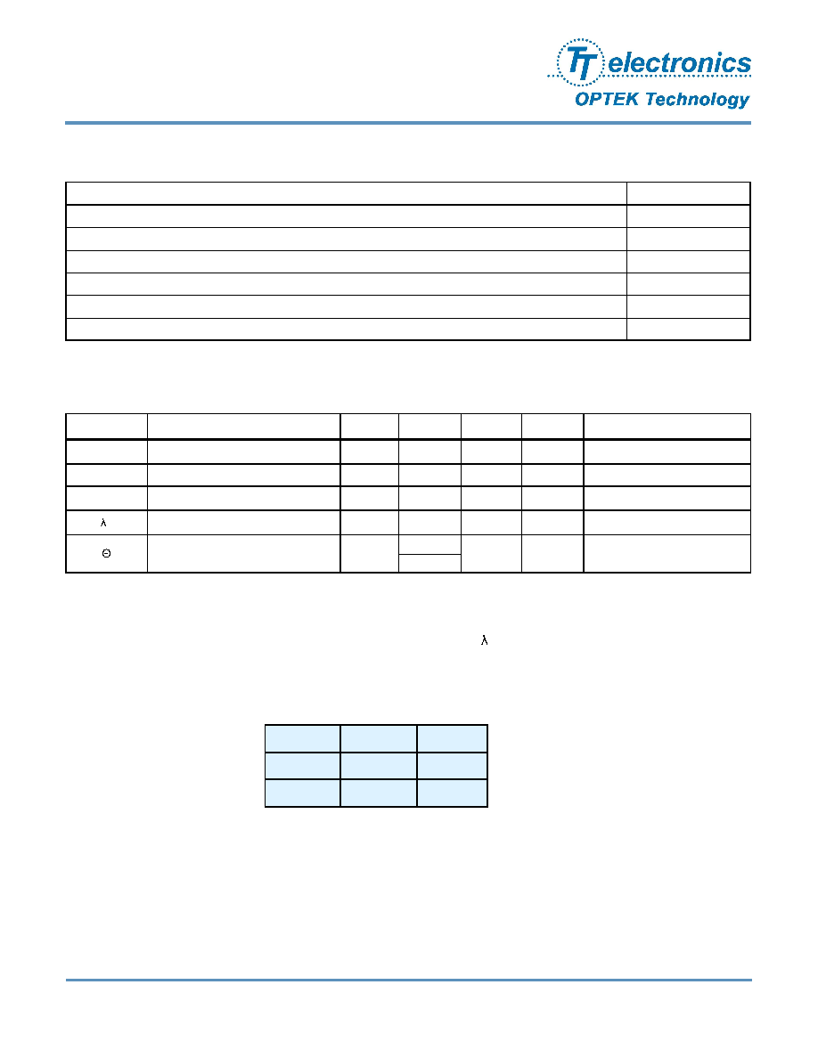
Absolute Maximum Ratings
T
A
= 25
o
C unless otherwise noted
Storage Temperature Range
-40 ~ +100 �C
Operating Temperature Range
-30 ~ +80 �C
Reverse Voltage
5 V
Continuous Forward Current
30 mA
Peak Forward Current (10% Duty Cycle, 1KHz)
100 mA
Lead Soldering Temperature (5 seconds max)
260� C
Power Dissipation
120 mW
Electrical Characteristics
T
A
= 25
o
C unless otherwise noted
SYMBOL
PARAMETER
MIN
TYP
MAX
UNITS
CONDITIONS
I
V
Luminous Intensity
725
1100
----
mcd
I
F
= 20 mA
V
F
Forward Voltage
----
3.3
3.9
V
I
F
= 20 mA
I
R
Reverse Current
----
----
2
�A
V
R
= 5V
D
Dominant Wavelength
520
525
535
nm
I
F
= 20 mA
2 �
50% Power Angle
----
x: 100
----
deg
y: 60
I
F
= 20 mA
Standard Bins
(I
F
= 20mA)
Lamps are sorted to luminous intensity (I
V
) and dominant wavelength (
D
) bins shown.
Orders for OVLKGGT6 may be filled with any or all bins contained as below.
Important Notes:
1. All ranks will be included per delivery, rank ratio will be based on the chip distribution.
2. To designate luminous intensity ranks, please contact OPTEK.
3. When soldering, leave 2.5mm minimum clearance between the resin base and the soldering point.
L
u
m
i
n
o
u
s
I
n
t
e
n
s
i
t
y
(
m
c
d
)
1045
5
870
4
725
3
Dominant Wavelength (nm)
525
530
535
520
Luminous intensity is
at 3 bin or above.

Issue 1.0 0505
Page 3
OPTEK Technology Inc. --
1645 Wallace Drive, Carrollton, Texas 75006
Phone: (972) 323-2200 or (800) 341-4747 FAX: (972) 323-2396 visibleLED@optekinc.com www.optekinc.com
Typical Electro-Optical Characteristics Curves
Maximum Forward DC Current vs. Ambient
Temperature
mA
�C
Relative Luminous Intensity vs. Wavelength
%
nm
Oval Green LED Lamp (3mm)
OVLKGGT6
Forward Current vs. Forward Voltage
V
mA
Relative Luminous Intensity vs. Forward Current
mA
%
Issue 1.0 0505
Page 4
OPTEK Technology Inc. --
1645 Wallace Drive, Carrollton, Texas 75006
Phone: (972) 323-2200 or (800) 341-4747 FAX: (972) 323-2396 visibleLED@optekinc.com www.optekinc.com
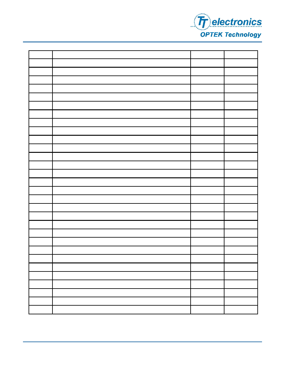
Issue
Change Description
Approval
Date
1.0
Initial Release
J. Haynie
5/26/05
Oval Green LED Lamp (3mm)
OVLKGGT6