 | –≠–ª–µ–∫—Ç—Ä–æ–Ω–Ω—ã–π –∫–æ–º–ø–æ–Ω–µ–Ω—Ç: F0372A | –°–∫–∞—á–∞—Ç—å:  PDF PDF  ZIP ZIP |

F 0372A
InGaAlP Resonant Cavity LED-Chip (660nm, High Power)
InGaAlP Resonant Cavity LED Chip (660 nm, High Power)
Vorl‰ufige Daten / Preliminary Data
2002-02-21
1
Besondere Merkmale
∑ keine Schwelle
∑ hohe Leistung
∑ Kurze Schaltzeiten: 15ns
∑ Oberfl‰chenstrahler
∑ Optimale Wellenl‰nge f¸r
Kunstoff-Faser¸bertragung
∑ Verbesserte Richtungsabh‰ngigkeit
∑ Verbesserte Einkoppeleffizienz
∑ Herausragende Zuverl‰ssigkeit
Anwendungen
∑ Drucker- und Scanneranwendungen
∑ Optische Plastikfaser-Daten¸bertragung im
Automobil
∑ Optische Sensoranwendungen
∑ Optische Anzeigen
Typ
Type
Bestellnummer
Ordering Code
Beschreibung
Description
F372A
on request
Resonant Cavity LED, Oberseite Anodenanschluss,
Leistungsvariante
Resonant Cavity LED, top side anode connection, Power
version
Features
∑ No threshold
∑ High Power
∑ Short Switching times: 15ns
∑ Surface emitter
∑ Optimized wavelength for plastic optical fiber
∑ Enhanced directionality
∑ Enhanced coupling efficiency
∑ extraordinary reliability
Applications
∑ Printer- and Scannerapplications
∑ Automotive plastic optical fiber communication
∑ Optical sensorapplications
∑ Optical indicators
2002-02-21
2
F 0372A
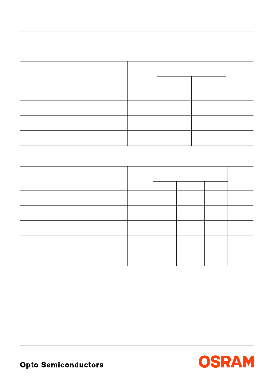
Grenzwerte
3)
(
T
A
= 25
∞
C)
Maximum Ratings
3)
Parameter
Parameter
Symbol
Symbol
Werte
Values
Einheit
Unit
min.
max.
Betriebstemperatur
Operating temperature
T
op
≠ 40
+ 85
∞
C
Durchlassstrom
Forward current
I
F
≠
30
mA
Stoþstrom,
t
p
=10µs, D=0.005
Surge current
I
S
≠
500
mA
Sperrspannung
Reverse voltage
V
R
12
≠
V
Mechanische Werte
Mechanical values
Bezeichnung
Parameter
Symbol
Symbol
Wert
1)
Value
1)
Einheit
Unit
min.
typ.
max.
Chipkantenl‰nge (x-Richtung)
Length of chip edge (x-direction)
L
x
0.2
0.22
0.24
mm
Chipkantenl‰nge (y-Richtung)
Length of chip edge (y-direction)
L
y
0.2
0.22
0.24
mm
Durchmesser des Wafers
Diameter of the wafer
D
W
100
mm
Chiphˆhe
Die height
H
200
220
240
µm
Bondpadkantenl‰nge
Bondpadsize
d
104
109
114
µm

F 0372A
2002-02-21
3
Optische Kennwerte (
T
A
= 25
∞
C)
Optical Characteristics
Parameter
Parameter
Symbol
Symbol
Werte
1)
Values
1)
Einheit
Unit
min.
typ.
max.
Emissionswellenl‰nge (gemessen in
Ulbrichtkugel)
Wavelength at peak emission (measured in
integrating sphere)
peak
640
650
660
nm
Spektralbreite (Halbwertsbreite, gemessen in
Ulbrichtkugel)
Spectral width (FWHM, measured in
integrating sphere)
12
18
nm
Spektralbreite (Halbwertsbreite,
Gemessen in
Achsrichtung (Raumwinkel 0.01sr)
)
Spectral width (FWHM,
Measured in axial
direction (Solid angle 0.01sr)
)
4
6
nm
Durchlassspannung
Forward voltage
I
F
= 20 mA
V
F
1.8
1.9
2.3
V
Gesamtstrahlungsfluss
4)
Total radiant flux
4)
I
F
= 20 mA
e
1.4
2.0
2.8
mW
Strahlst‰rke
4)
Radiant intensity
4)
I
F
= 20 mA
I
e
0.4
0.7
1.2
mW/sr
Anstiegs- und Abfallzeit (10% ... 90%)
Rise and fall time (10% ... 90%)
t
r
,
t
f
15
ns
Temperaturkoeffizient der Wellenl‰nge
Temperature coefficient of wavelength
/
T
0.1
nm/K
Temperaturkoeffizient der Durchlassspannung
Temperature coefficient of forward voltage
V
F
/
T
-0.18
mV/K
F 0372A
2002-02-21
4
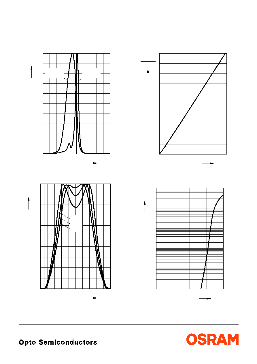
Relative Spectral Emission
2)
I
rel
=
f
(
), T
A
= 25∞C
Radiation Characteristics
2)
I
rel
=
f
(
)
Radiant Intensity
2)
T
A
= 25∞C
Forward Current
2)
I
F
=
f
(V
F
), T
A
= 25∞C
OHF00149
0
600
nm
rel
%
10
20
30
40
50
60
70
80
90
100
620
640
660
680
700
total
emission
emission
front
OHF00147
0
-100
rel
%
10
20
30
40
50
60
70
80
90
100
-50
0
50
100
Deg.
25 ∞C
60 ∞C
90 ∞C
e
e
10 mA
=
f
(
I
F
)
OHF00632
mA
e
0
I
F
0
e (10 mA)
5
10
15
20
0,2
0,4
0,6
0,8
1,0
1,2
1,4
1,6
2,0
10
10
-3
10
-2
-1
10
0
10
1
10
2
OHF00631
0
I
F
V
F
V
mA
0,5
1,0
1,5
2,0

F 0372A
2002-02-21
5
Maþzeichnung
Chip Outlines
Maþe werden als typische
1)
Werte wie folgt angegeben: mm (inch) / Dimensions are specified as typical
1)
values as
follows: mm (inch).
GCOY6911
0.22 (0.0087)
0.109 (0.0043)
p-contact
n-contact
0.22 (0.0087)