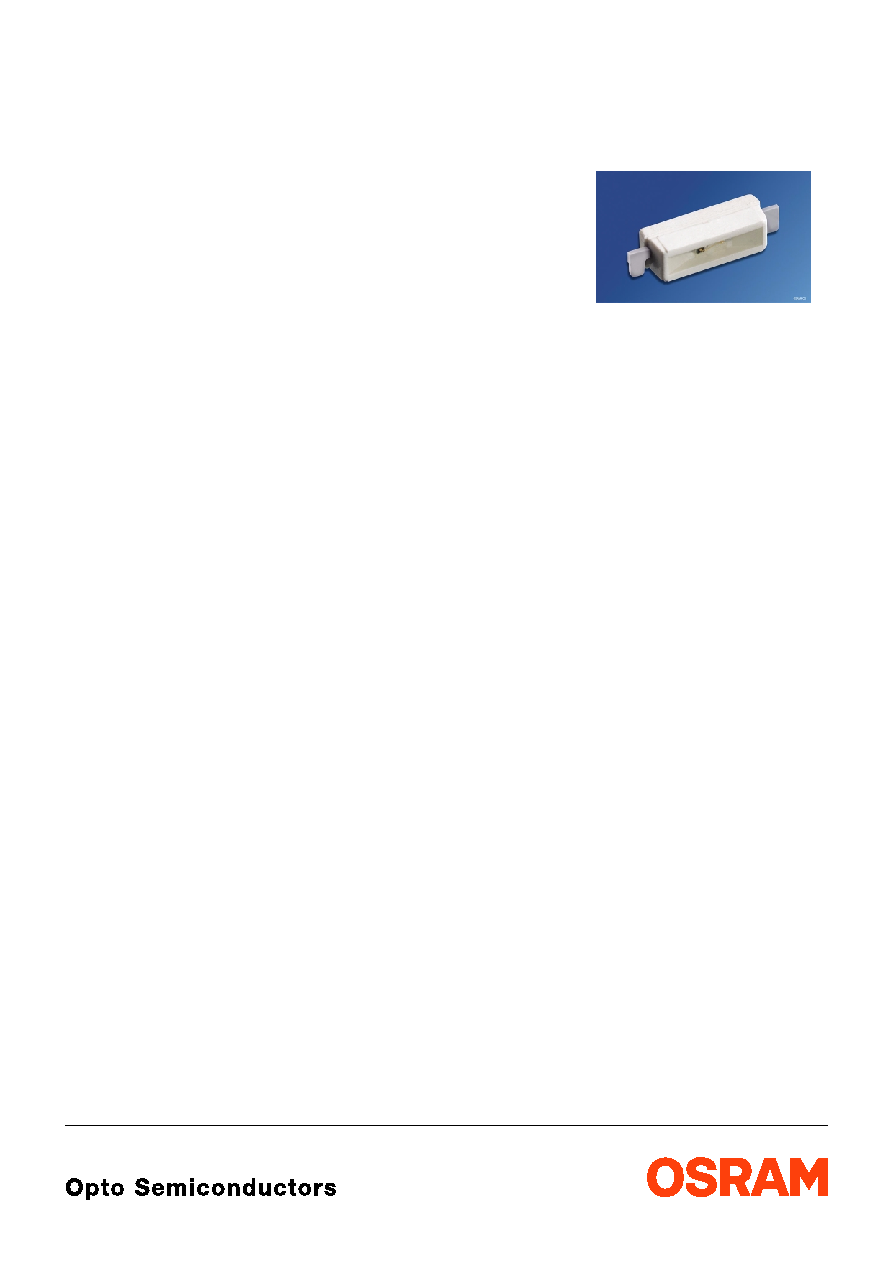
LB C876
BLUE LINE
TM
Hyper Mini SIDELED
Hyper-Bright LED
2001-11-14
1
Besondere Merkmale
Ј Gehдusetyp: weiяes SMT Gehдuse
Ј Besonderheit des Bauteils: flacher, kleiner
Seitenstrahler fьr Einkopplungen in Lichtleiter
Ј Wellenlдnge: 465 nm
Ј Abstrahlwinkel: Lambertscher Strahler (120∞)
Ј Technologie: GaN
Ј optischer Wirkungsgrad: 1 lm/W
Ј Gruppierungsparameter: Lichtstдrke
Ј Verarbeitungsmethode: fьr alle
SMT-Bestьcktechniken geeignet
Ј Lцtmethode: IR Reflow Lцten
Ј Vorbehandlung: nach JEDEC Level 2
Ј Gurtung: 12 mm Gurt mit 2500/Rolle, ш180 mm
oder 10000/Rolle, ш330 mm
Ј ESD-Festigkeit: ESD-sicher bis 2 kV nach
EOS/ESD-5.1-1993
Anwendungen
Ј optischer Indikator
Ј Einkopplung in Lichtleiter
Ј Hinterleuchtung (LCD, Handy, Schalter,
Tasten, Displays, Werbebeleuchtung,
Allgemeinbeleuchtung)
Ј Innenbeleuchtung im Automobilbereich
(z.B. Instrumentenbeleuchtung, u.д.)
Features
Ј package: white SMT package
Ј feature of the device: flat, small sidelooker for
coupling in light guides
Ј wavelength: 465 nm
Ј viewing angle: Lambertian Emitter (120∞)
Ј technology: GaN
Ј optical efficiency: 1 lm/W
Ј grouping parameter: luminous intensity
Ј assembly methods: suitable for all
SMT assembly methods
Ј soldering methods: IR reflow soldering
Ј preconditioning: acc. to JEDEC Level 2
Ј taping: 12 mm tape with 2500/reel, ш180 mm
or 10000/reel, ш330 mm
Ј ESD-withstand voltage: up to 2 kV acc. to
EOS/ESD-5.1-1993
Applications
Ј optical indicators
Ј coupling into light guides
Ј backlighting (LCD, cellular phones, switches,
keys, displays, illuminated advertising,
general lighting)
Ј interior automotive lighting (e.g. dashboard
backlighting, etc.)
2001-11-14
2
LB C876
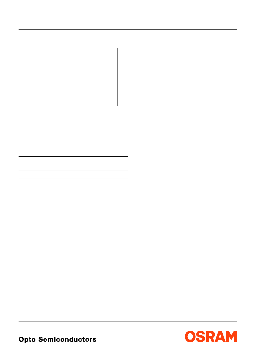
Anm.: -1 gesamter Farbbereich
Die Standardlieferform von Serientypen beinhaltet eine untere bzw. eine obere Familiengruppe,
die aus nur 3 bzw. 4 Halbgruppen besteht. Einzelne Halbgruppen sind nicht erhдltlich.
In einer Verpackungseinheit / Gurt ist immer nur eine Halbgruppe enthalten.
Note: -1 Total color tolerance range
The standard shipping format for serial types includes a lower or upper family group of 3 or 4
individual groups. Individual half groups are not available.
No packing unit / tape ever contains more than one luminous intensity half group.
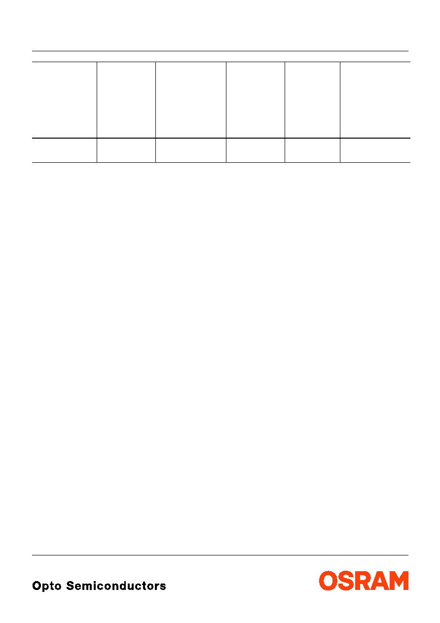
Typ
Type
Emissions-
farbe
Color of
Emission
Farbe der
Lichtaustritts-
flдche
Color of the
Light Emitting
Area
Lichtstдrke
Luminous
Intensity
I
F
= 10 mA
I
V
(mcd)
Lichtstrom
Luminous
Flux
I
F
= 10 mA
V
(mlm)
Bestellnummer
Ordering Code
LB C876-J1K1-1
LB C876-K1L2-1
blue
colorless clear
4.5 ...
9.0
7.1 ... 18.0
20 (typ.)
36 (typ.)
Q62703-Q4988
Q62703-Q4989
LB C876
2001-11-14
3
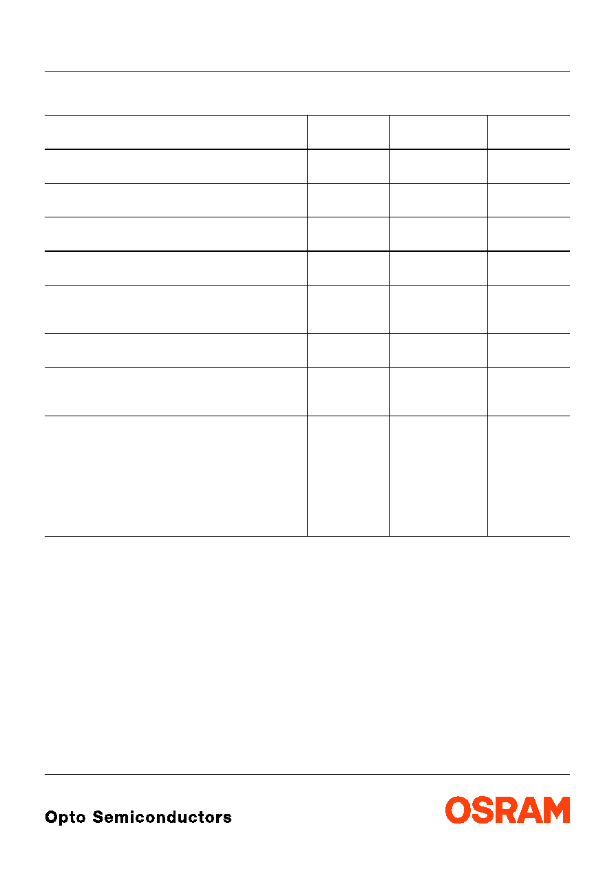
Grenzwerte
Maximum Ratings
Bezeichnung
Parameter
Symbol
Symbol
Wert
Value
Einheit
Unit
Betriebstemperatur
Operating temperature range
T
op
≠ 40 ... + 100
∞C
Lagertemperatur
Storage temperature range
T
stg
≠ 40 ... + 100
∞C
Sperrschichttemperatur
Junction temperature
T
j
+ 100
∞C
Durchlassstrom
Forward current
I
F
20
mA
Stoяstrom
Surge current
t
10
µ
s,
D
= 0.005
I
FM
0.2
A
Sperrspannung
Reverse voltage
V
R
5
V
Leistungsaufnahme
Power consumption
T
A
25 ∞C
P
tot
90
mW
Wдrmewiderstand
Thermal resistance
Sperrschicht/Umgebung
Junction/air
Sperrschicht/Lцtpad
Junction/solder point
Montage auf PC-Board FR 4 (Padgrцяe
16 mm
2
)
mounted on PC board FR 4 (pad size
16 mm
2
)
R
th JA
R
th JS
630
350
K/W
K/W
2001-11-14
4
LB C876
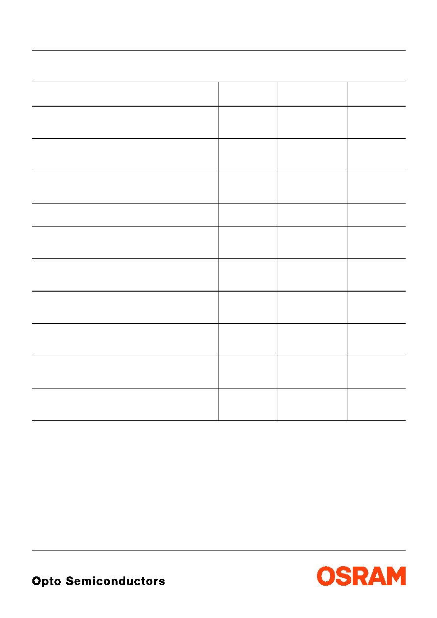
Kennwerte (
T
A
= 25 ∞C)
Characteristics
Bezeichnung
Parameter
Symbol
Symbol
Werte
Values
Einheit
Unit
Wellenlдnge des emittierten Lichtes
(typ.)
Wavelength at peak emission
I
F
= 10 mA
peak
428
nm
Dominantwellenlдnge
1)
Dominant wavelength
1)
I
F
= 10 mA
dom
465 ± 3
nm
nm
Spektrale Bandbreite bei 50 %
I
rel max
(typ.)
Spectral bandwidth at 50 %
I
rel max
I
F
= 10 mA
60
nm
Abstrahlwinkel bei 50 %
I
V
(Vollwinkel)
(typ.)
Viewing angle at 50 %
I
V
2
120
Grad
deg.
Durchlassspannung
2)
(typ.)
Forward voltage
2)
(max.)
I
F
= 10 mA
V
F
V
F
3.5
4.1
V
V
Sperrstrom
(typ.)
Reverse current
(max.)
V
R
= 5 V
I
R
I
R
0.01
10
µ
A
µ
A
Temperaturkoeffizient von
peak
(typ.)
Temperature coefficient of
peak
I
F
= 10 mA; ≠10∞C
T
100∞C
TC
peak
0.004
nm/K
Temperaturkoeffizient von
dom
(typ.)
Temperature coefficient of
dom
I
F
= 10 mA; ≠10∞C
T
100∞C
TC
dom
0.03
nm/K
Temperaturkoeffizient von
V
F
(typ.)
Temperature coefficient of
V
F
I
F
= 10 mA; ≠10∞C
T
100∞C
TC
V
≠ 3.1
mV/K
Optischer Wirkungsgrad
(typ.)
Optical efficiency
I
F
= 10 mA
opt
1
lm/W
1)
Wellenlдngen werden mit einer Stromeinprдgedauer von 25 ms und einer Genauigkeit von ±1 nm ermittelt.
Wavelengths are tested at a current pulse duration of 25 ms and a tolerance of ±1 nm.
2)
Spannungswerte werden mit einer Stromeinprдgedauer von 1 ms und einer Genauigkeit von ±0,1 V ermittelt.
Voltages are tested at a current pulse duration of 1 ms and a tolerance of ±0.1 V.
LB C876
2001-11-14
5
Helligkeitswerte werden mit einer Stromeinprдgedauer von 25 ms und einer Genauigkeit von
±
11% ermittelt.
Luminous intensity is tested at a current pulse duration of 25 ms and a tolerance of
±
11%.
Helligkeits-Gruppierungsschema
Luminous Intensity Groups
Lichtgruppe
Luminous Intensity Group
Lichtstдrke
Luminous Intensity
I
V
(mcd)
Lichtstrom
Luminous Flux
V
(mlm)
J1
J2
K1
K2
L1
L2
4.5 ...
5.6
5.6 ...
7.1
7.1 ...
9.0
9.0 ... 11.2
11.2 ... 14.0
14.0 ... 18.0
15 (typ.)
19 (typ.)
24 (typ.)
30 (typ.)
40 (typ.)
50 (typ.)
Gruppenbezeichnung auf Etikett
Group Name on Label
Beispiel: K2
Example: K2
Lichtgruppe
Luminous Intensity Group
Halbgruppe
Half Group
K
2

2001-11-14
6
LB C876
Relative spektrale Emission
I
rel
=
f
(
),
T
A
= 25 ∞C,
I
F
= 10 mA
Relative Spectral Emission
V(
) = spektrale Augenempfindlichkeit
Standard eye response curve
Abstrahlcharakteristik
I
rel
=
f
(
)
Radiation Characteristic
OHL00431
380
0
20
40
60
80
100
%
I
rel
V
blue
430
480
530
580
630
680
nm
0
0.2
0.4
1.0
0.8
0.6
1.0
0.8
0.6
0.4
0∞
10∞
20∞
40∞
30∞
OHL01660
50∞
60∞
70∞
80∞
90∞
100∞
0∞
20∞
40∞
60∞
80∞
100∞
120∞
LB C876
2001-11-14
7
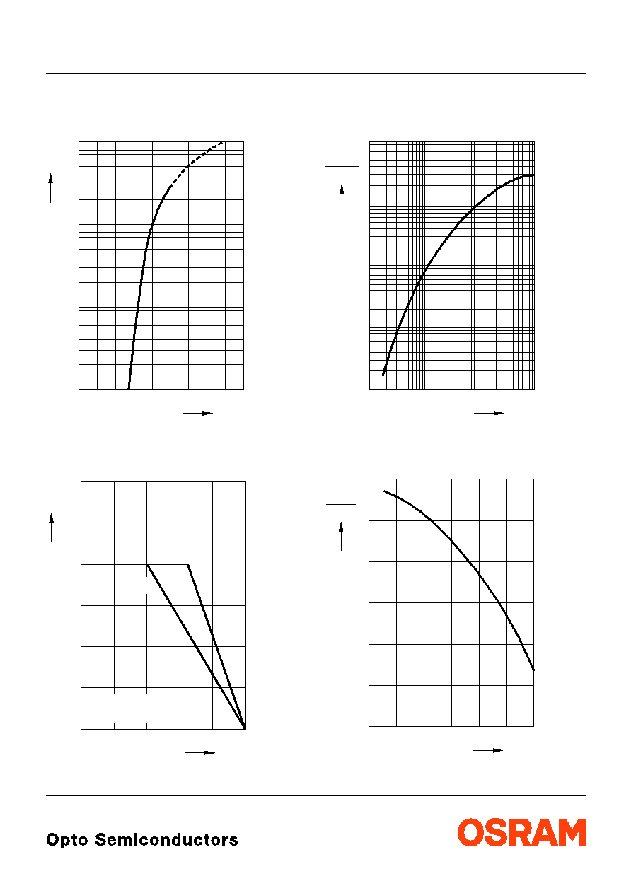
Durchlassstrom
I
F
=
f
(
V
F
)
Forward Current
T
A
= 25 ∞C
Maximal zulдssiger Durchlassstrom
I
F
=
f
(
T
)
Max. Permissible Forward Current
Relative Lichtstдrke
I
V
/
I
V(10 mA)
=
f
(
I
F
)
Relative Luminous Intensity
T
A
= 25 ∞C
Relative Lichtstдrke
I
V
/
I
V(25 ∞C)
=
f
(
T
A
)
Relative Luminous Intensity
I
F
= 10 mA
V
OHL00432
F
F
I
V
5
1.5
2 2.5 3 3.5 4 4.5 5
6
10
-1
0
10
5
1
10
5
10
2
T
OHL00451
0
F
I
0
20
40
60
80 ∞C 100
mA
5
10
15
20
25
30
temp. solder point
temp. ambient
T
T
S
A
T
A
T
S
I
OHL00433
F
-1
10
V (10 mA)
I
10
-3
-2
-1
0
1
10
10
10
10
10
0
10
1
10
2
5
5
5
5
5
mA
I
V
OHL00442
0
V
I
-20
0
20
40
60
∞C 100
A
I
V
(25 ∞C)
0.2
0.4
0.6
0.8
1.2
T
LB C876
2001-11-14
8
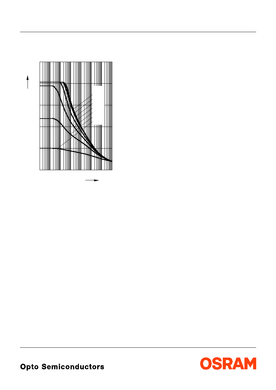
Zulдssige Impulsbelastbarkeit
I
F
=
f
(
t
p
)
Permissible Pulse Handling Capability
Duty cycle
D
= parameter,
T
A
= 25 ∞C
Zulдssige Impulsbelastbarkeit
I
F
=
f
(
t
p
)
Permissible Pulse Handling Capability
Duty cycle
D
= parameter,
T
A
= 85 ∞C
OHL01251
mA
t
P
F
I
-5
10
0
-4
10
-3
10
-2
10
-1
10
0
10
1
10
2
10
s
50
100
150
200
250
0.5
0.1
0.2
0.05
0.005
0.01
0.02
D
=

LB C876
2001-11-14
9
Maяzeichnung
Package Outlines
Maяe werden wie folgt angegeben: mm (inch) / Dimensions are specified as follows: mm (inch).
Kathodenkennung:
abgeschrдgte Ecke
Cathode mark:
bevelled edge
Gewicht / Approx. weight: 20 mg
GPLY6930
5.8 (0.228)
5.4 (0.213)
0.8 (0.031)
1.2 (0.047)
1.6 (0.063)
1.2 (0.047)
Cathode
0.4 (0.016)
0.6 (0.024)
0...0.1 (0.004)
4.2 (0.165)
4.6 (0.181)
1.8 (0.071)
1.5 (0.059)
(0.8 (0.031))
0.20 (0.008)
0.25 (0.010)
(0.6 (0.024))
2001-11-14
10
LB C876
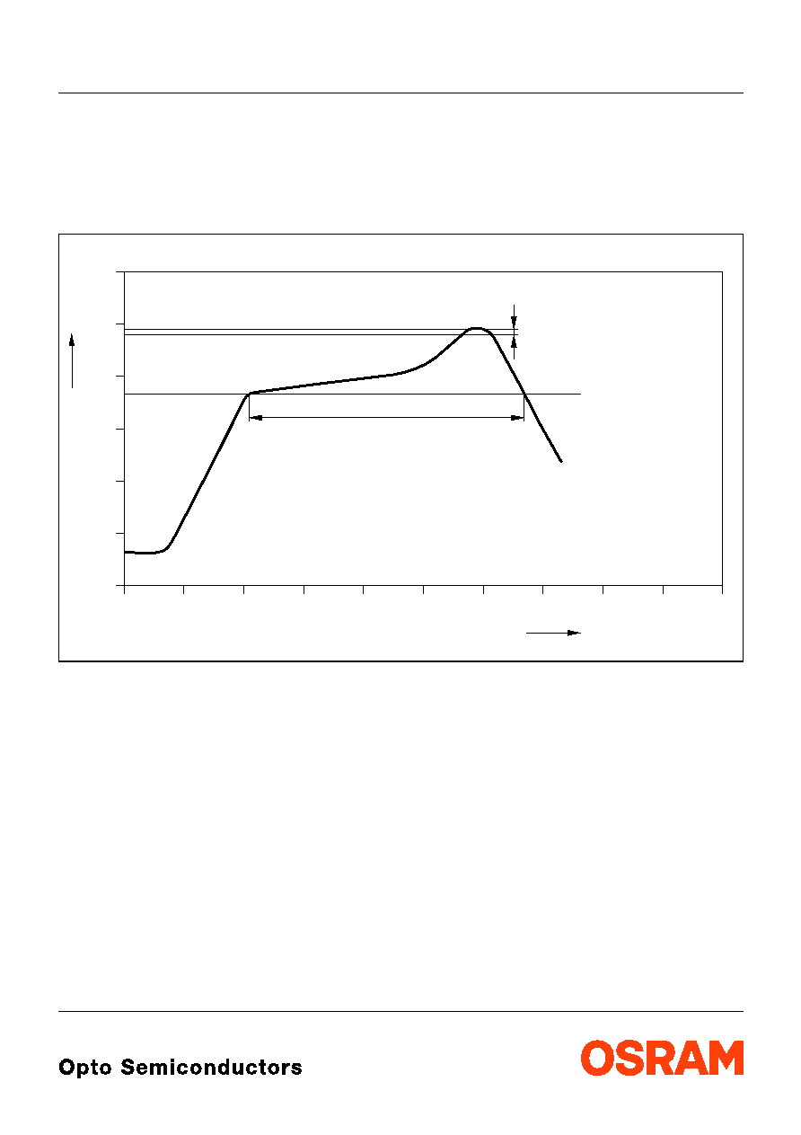
Lцtbedingungen
Vorbehandlung nach JEDEC Level 2
Soldering Conditions Preconditioning acc. to JEDEC Level 2
IR-Reflow Lцtprofil
(nach IPC 9501)
IR Reflow Soldering Profile
(acc. to IPC 9501)
OHLY0597
0
0
50
100
150
200
250
50
100
150
200
250
300
T
t
∞C
s
240-245 ∞C
10-40 s
183 ∞C
120 to 180 s
Defined for Preconditioning: up to 6 K/s
Ramp-down rate up to 6 K/s
Ramp-up rate up to 6 K/s
Defined for Preconditioning: 2-3 K/s
LB C876
2001-11-14
11
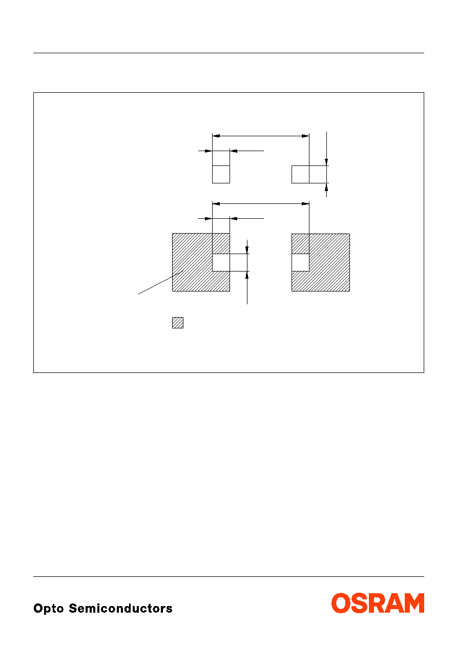
Empfohlenes Lцtpaddesign
IR Reflow Lцten
Recommended Solder Pad
IR Reflow Soldering
Maяe werden wie folgt angegeben: mm (inch) / Dimensions are specified as follows: mm (inch).
OHLPY981
6.6 (2.598)
1.2 (0.472)
for improved
heat dissipation
Cu-area > 16 mm
Cu-Flдche > 16 mm
Wдrmeableitung
fьr verbesserte
Padgeometrie
Paddesign
2
2
Solder resist
Lцtstopplack
1.2 (0.472)
6.6 (2.598)
1.2 (0.472)
1.2 (0.472)
2001-11-14
12
LB C876
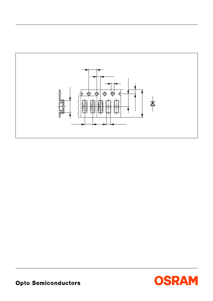
Gurtung / Polaritдt und Lage
Verpackungseinheit 2500/Rolle, ш180 mm
oder 10000/Rolle, ш330 mm
Method of Taping / Polarity and Orientation Packing unit 2500/reel, ш180 mm
or 10000/reel, ш330 mm
Maяe werden wie folgt angegeben: mm (inch) / Dimensions are specified as follows: mm (inch).
OHAY0226
A
C
4 (0.157)
1.5 (0.059)
1.8 (0.071)
6 (0.236)
5.5 (0.217)
1.75 (0.069)
12 (0.472)
2 (0.079)
4 (0.157)
LB C876
2001-11-14
13
Published by OSRAM Opto Semiconductors GmbH & Co. OHG
Wernerwerkstrasse 2, D-93049 Regensburg
© All Rights Reserved.
Attention please!
The information describes the type of component and shall not be considered as assured characteristics.
Terms of delivery and rights to change design reserved. Due to technical requirements components may contain
dangerous substances. For information on the types in question please contact our Sales Organization.
If printed or downloaded, please find the latest version in the Internet.
Packing
Please use the recycling operators known to you. We can also help you ≠ get in touch with your nearest sales office.
By agreement we will take packing material back, if it is sorted. You must bear the costs of transport. For packing
material that is returned to us unsorted or which we are not obliged to accept, we shall have to invoice you for any costs
incurred.
Components used in life-support devices or systems must be expressly authorized for such purpose! Critical
components
1
may only be used in life-support devices or systems
2
with the express written approval of OSRAM OS.
1
A critical component is a component used in a life-support device or system whose failure can reasonably be expected
to cause the failure of that life-support device or system, or to affect its safety or the effectiveness of that device or
system.
2
Life support devices or systems are intended (a) to be implanted in the human body, or (b) to support and/or maintain
and sustain human life. If they fail, it is reasonable to assume that the health of the user may be endangered.
Revision History: 2001-11-14
Previous Version:
2001-02-08
Page
Subjects (major changes since last revision)
4
Dominant wavelength