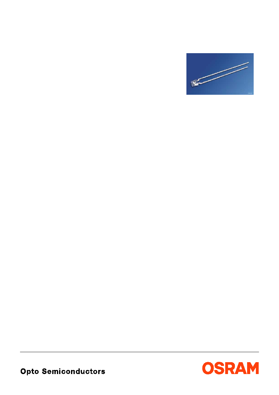
LS K376, LO K376, LY K376
Hyper ARGUS
ģ
LED
Hyper-Bright, 3mm (T1) LED, Non Diffused
2003-10-14
1
Besondere Merkmale
∑ Gehšusetyp: nicht eingefšrbtes, klares
3 mm (T1) Gehšuse mit spezieller Linse
∑ Besonderheit des Bauteils: mit Einsatz eines
šuŖeren Reflektors zur Hinterleuchtung von
Leuchtfeldern und LCD-Anzeigen; LŲtspieŖe
mit Aufsetzebene
∑ Wellenlšnge: 633 nm (super-rot),
606 nm (orange), 587 nm (gelb)
∑ Abstrahlwinkel: angepasst an Einsatz mit
šuŖerem Reflektor, siehe Diagramm
∑ Technologie: InGaAlP
∑ optischer Wirkungsgrad: 11 lm/W (gelb,
orange), 7 lm/W (super-rot)
∑ Gruppierungsparameter: Lichtstrom
∑ LŲtmethode: WellenlŲten (TTW)
∑ Verpackung: SchŁttgut, gegurtet lieferbar
∑ ESD-Festigkeit: ESD-sicher bis 2 kV nach
JESD22-A114-B
Anwendungen
∑ Hinterleuchtung (LCD, Schalter, Tasten,
Displays, Werbebeleuchtung,
Allgemeinbeleuchtung)
∑ Innenbeleuchtung im Automobilbereich
(z.B. Instrumentenbeleuchtung, u.š.)
∑ Einkopplung in Lichtleiter
Features
∑ package: colorless, clear 3 mm (T1) package
with specially shaped lens
∑ feature of the device: for backlighting and
LCDs with use of a reflector; solder leads with
stand-off
∑ wavelength: 633 nm (super-red),
606 nm (orange), 587 nm (yellow)
∑ viewing angle: matched to use with external
reflector, see diagram
∑ technology: InGaAlP
∑ optical efficiency: 11 lm/W (yellow, orange),
7 lm/W (super-red)
∑ grouping parameter: luminous flux
∑ soldering methods: TTW soldering
∑ packing: bulk, available taped on reel
∑ ESD-withstand voltage: up to 2 kV acc. to
JESD22-A114-B
Applications
∑ backlighting (LCD, switches, keys, displays,
illuminated advertising, general lighting)
∑ interior automotive lighting (e.g. dashboard
backlighting, etc.)
∑ coupling into light guides!
2003-10-14
2
LS K376, LO K376, LY K376,
Anm.: -1 gesamter Farbbereich (siehe Seite 4)
-24 gesamter Farbbereich, Lieferung in Einzelgruppen (siehe Seite 5)
-26 gesamter Farbbereich, Lieferung in Einzelgruppen (siehe Seite 5)
Note: -1 Total color tolerance range (please see page 4)
-24 Total color tolerance range, delivery in single groups (please see page 5)
-26 Total color tolerance range, delivery in single groups (please see page 5)
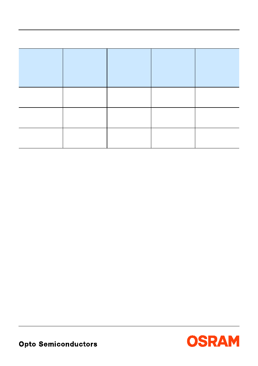
Bestellinformation
Ordering Information
Typ
Type
Emissions-
farbe
Color of
Emission
Gehšusefarbe
Color of
Package
Lichtstrom
1)
Seite 12
Luminous Flux
1)
page 12
I
F
= 20 mA
V
(mlm)
Bestellnummer
Ordering Code
LS K376-S1T2-1
LS K376-T1U2-1
LS K376-S1U2-1
super-red
colorless clear
180 ... 450
280 ... 710
180 ... 710
Q65110A1377
Q65110A1380
Q65110A1378
LO K376-T1U2-24
LO K376-U1V2-24
LO K376-T1V2-24
orange
colorless clear
280 ... 710
450 ... 1120
280 ... 1120
Q65110A1347
Q65110A1349
Q65110A1348
LY K376-T1U2-26
LY K376-U1V2-26
LY K376-T1V2-26
yellow
colorless clear
280 ... 710
450 ... 1120
280 ... 1120
Q65110A1409
Q65110A1411
Q65110A1410
LS K376, LO K376, LY K376,
2003-10-14
3
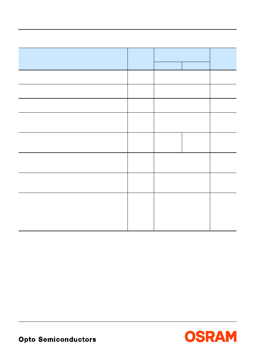
Grenzwerte
Maximum Ratings
Bezeichnung
Parameter
Symbol
Symbol
Werte
Values
Einheit
Unit
LS, LO
LY
Betriebstemperatur
Operating temperature range
T
op
≠ 55 ... + 100
įC
Lagertemperatur
Storage temperature range
T
stg
≠ 55 ... + 100
įC
Sperrschichttemperatur
Junction temperature
T
j
+ 100
įC
Durchlassstrom
Forward current
(
T
A
=25įC)
I
F
30
mA
StoŖstrom
Surge current
t
10
Ķ
s,
D
= 0.005,
T
A
=25įC
I
FM
1
0.2
A
Sperrspannung
3)
Seite 12
Reverse voltage
3)
page 12
(
T
A
=25įC)
V
R
12
V
Leistungsaufnahme
Power consumption
(
T
A
=25įC)
P
tot
80
mW
Wšrmewiderstand
4)
Seite 12
Thermal resistance
4)
page 12
Sperrschicht/Umgebung
5)
Seite 12
Junction/ambient
5)
page 12
Sperrschicht/LŲtpad
Junction/solder point
R
th JA
R
th JS
500
280
K/W
K/W

2003-10-14
4
LS K376, LO K376, LY K376,
Kennwerte
Characteristics
(
T
A
= 25 įC)
Bezeichnung
Parameter
Symbol
Symbol
Werte
Values
Einheit
Unit
LS
LO
LY
Wellenlšnge des emittierten Lichtes
(typ.)
Wavelength at peak emission
I
F
= 20 mA
peak
645
610
591
nm
Dominantwellenlšnge
6)
Seite 12
(typ.)
Dominant wavelength
6)
page 12
I
F
= 20 mA
dom
633
606*
587*
nm
Spektrale Bandbreite bei 50 %
I
rel max
(typ.)
Spectral bandwidth at 50 %
I
rel max
I
F
= 20 mA
16
16
15
nm
Durchlassspannung
7)
Seite 12
(min.)
Forward voltage
7)
page 12
(typ.)
I
F
= 20 mA
(max.)
V
F
V
F
V
F
1.8
2.0
2.3
1.85
2.0
2.35
1.9
2.0
2.4
V
V
V
Sperrstrom
(typ.)
Reverse current
(max.)
V
R
= 12 V
I
R
I
R
0.01
10
0.01
10
0.01
10
Ķ
A
Ķ
A
Temperaturkoeffizient von
peak
(typ.)
Temperature coefficient of
peak
I
F
= 20 mA; ≠10įC
T
100įC
TC
peak
0.14
0.13
0.13
nm/K
Temperaturkoeffizient von
dom
(typ.)
Temperature coefficient of
dom
I
F
= 20 mA; ≠10įC
T
100įC
TC
dom
0.05
0.07
0.10
nm/K
Temperaturkoeffizient von
V
F
(typ.)
Temperature coefficient of
V
F
I
F
= 20 mA; ≠10įC
T
100įC
TC
V
≠ 2.0
≠ 1.7
≠ 2.5
mV/K
Optischer Wirkungsgrad
(typ.)
Optical efficiency
I
F
= 20 mA
opt
7
11
11
lm/W
* Einzelgruppen siehe Seite 5
Individual groups on page 5
LS K376, LO K376, LY K376,
2003-10-14
5
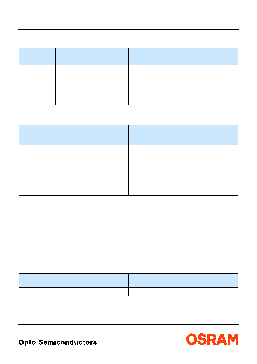
Wellenlšngengruppen (Dominantwellenlšnge)
6)
Seite 12
Wavelength Groups (Dominant Wavelength)
6)
page 12
Gruppe
Group
yellow
orange
Einheit
Unit
min.
max.
min.
max.
2
580
583
600
603
nm
3
583
586
603
606
nm
4
586
589
606
609
nm
5
589
592
nm
6
592
595
nm
Helligkeits-Gruppierungsschema
Brightness Groups
Helligkeitshalbgruppe
Brightness Half Group
Lichtstrom
1)
Seite 12
Luminous Flux
1)
page 12
V
(mlm)
S1
S2
T1
T2
U1
U2
V1
V2
180 ...
224
224 ...
280
280 ...
355
355 ...
450
450 ...
560
560 ...
710
710 ...
900
900 ... 1120
Anm.: Die Standardlieferform von Serientypen beinhaltet eine untere Familiengruppe, eine obere
Familiengruppe oder eine Sammelgruppe, die aus nur 4 bzw. 6 Helligkeitshalbgruppen
bestehen.
Einzelne Helligkeitshalbgruppen sind nicht bestellbar.
Note: The standard shipping format for serial types includes either a lower family group, an upper
family group or a grouping of all individual groups of 4 or 6 brightness half groups.
Individual brightness half groups cannot be ordered
Gruppenbezeichnung auf Etikett
Group Name on Label
Beispiel: T2-3
Example: T2-3
Helligkeitshalbgruppe
Brightness Half Group
Wellenlšnge
Wavelength
T2
3
Anm.: In einer Verpackungseinheit / Gurt ist immer nur eine Gruppe fŁr jede Selektion enthalten.
Note: No packing unit / tape ever contains more than one group for each selection.
2003-10-14
6
LS K376, LO K376, LY K376,
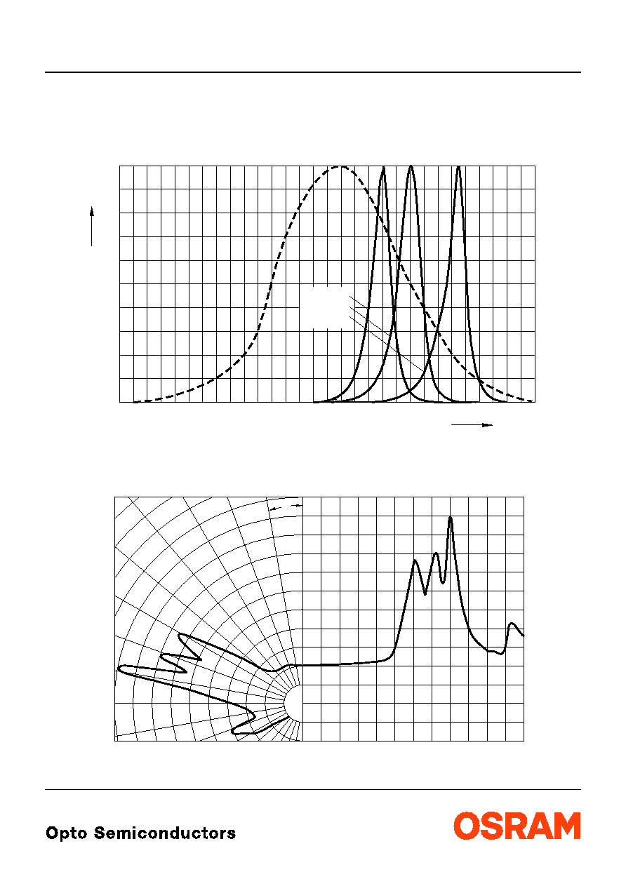
Relative spektrale Emission
2) Seite 12
Relative Spectral Emission
2) page 12
V(
) = spektrale Augenempfindlichkeit / Standard eye response curve
I
rel
=
f
(
);
T
A
= 25 įC;
I
F
= 20 mA
Abstrahlcharakteristik
2)
Seite 12
Radiation Characteristic
2)
page 12
I
rel
=
f
(
);
T
A
= 25 įC
OHL00841
400
0
20
40
60
80
100
450
500
550
600
650
700
nm
%
I
rel
V
yellow
orange
super-red
0
0.2
0.4
1.0
0.8
0.6
1.0
0.8
0.6
0.4
0į
10į
20į
40į
30į
OHL01277
50į
60į
70į
80į
90į
100į
0į
20į
40į
60į
80į
100į
120į
LS K376, LO K376, LY K376,
2003-10-14
7
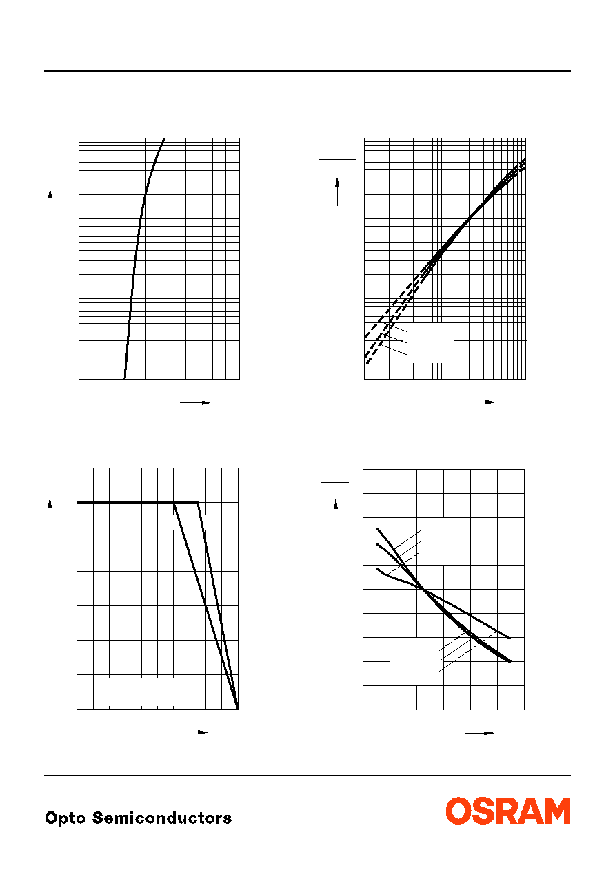
Durchlassstrom
2)
Seite 12
Forward Current
2)
page 12
I
F
=
f
(
V
F
);
T
A
= 25 įC
Maximal zulšssiger Durchlassstrom
Max. Permissible Forward Current
I
F
=
f
(
T
)
Relativer Lichtstrom
2) 8)
Seite 12
Relative Luminous Flux
2) 8)
page 12
V
/
V(20 mA)
=
f
(
I
F
);
T
A
= 25 įC
Relativer Lichtstrom
2)
Seite 12
Relative Luminous Flux
2)
page 12
V
/
V(25 įC)
=
f
(
T
A
);
I
F
= 20 mA
OHL00232
10
-1
1.4
1.8
2.2
2.6
3 V 3.4
0
10
1
10
10
2
5
5
mA
5
1
F
V
F
I
OHL01013
0
0
20
40
60
80 įC 100
T
I
F
temp. ambient
temp. solder point
A
S
T
T
5
10
15
20
25
30
35
A
T
S
T
mA
orange
super-red
10
10
10
0
-2
10
-1
yellow
mA
1
10
I
F
2
I
V (20 mA)
I
10
0
V
10
1
OHL00488
T
OHL00832
0
V
I
-20
0
20
40
60
įC 100
orange
A
0.4
0.8
1.2
1.6
2.0
I
V
(25 įC)
yellow
super-red
super-red
yellow
orange
LS K376, LO K376, LY K376,
2003-10-14
8
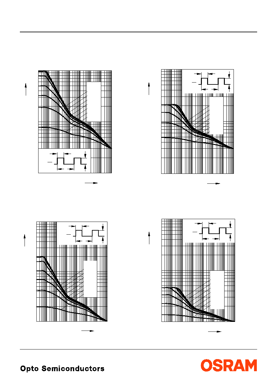
Zulšssige Impulsbelastbarkeit
I
F
=
f
(
t
p
)
Permissible Pulse Handling Capability
Duty cycle
D
= parameter,
T
A
= 25 įC
LS, LO
Zulšssige Impulsbelastbarkeit
I
F
=
f
(
t
p
)
Permissible Pulse Handling Capability
Duty cycle
D
= parameter,
T
A
= 85 įC
LS, LO
Zulšssige Impulsbelastbarkeit
I
F
=
f
(
t
p
)
Permissible Pulse Handling Capability
Duty cycle
D
= parameter,
T
A
= 25 įC
LY
Zulšssige Impulsbelastbarkeit
I
F
=
f
(
t
p
)
Permissible Pulse Handling Capability
Duty cycle
D
= parameter,
T
A
= 85 įC
LY
OHL00318
F
I
10
10
-5
-4
-3
10
10
-2
10
-1
10
0
s
10
1
10
2
p
t
0.05
0.5
0.2
0.1
D
0.02
0.01
0.005
=
-2
10
-1
10
0
10
5
5
A
D
T
t
=
P
t
T
P
I
F
OHL01414
F
I
10
10
-5
-4
-3
10
10
-2
10
-1
10
0
s
10
1
10
2
p
t
0.05
0.5
0.2
0.1
D
0.02
0.01
0.005
=
-2
10
-1
10
0
10
5
5
A
D
T
t
=
P
t
T
P
I
F
OHL00316
F
I
10
10
-5
-4
-3
10
10
-2
10
-1
10
0
s
10
1
10
2
p
t
0.05
0.5
0.2
0.1
D
0.02
0.01
0.005
=
-2
10
-1
10
0
10
5
5
A
D
T
t
=
P
t
T
P
I
F
OHL01415
F
I
10
10
-5
-4
-3
10
10
-2
10
-1
10
0
s
10
1
10
2
p
t
0.05
0.5
0.2
0.1
D
0.02
0.01
0.005
=
-2
10
-1
10
0
10
5
5
A
D
T
t
=
P
t
T
P
I
F
LS K376, LO K376, LY K376,
2003-10-14
9
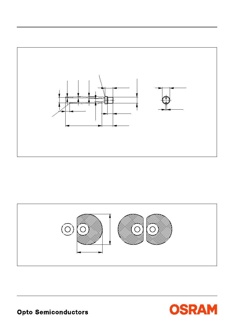
MaŖzeichnung
9)
Seite 12
Package Outlines
9)
page 12
Kathodenkennung:
kŁrzerer LŲtspieŖ
Cathode mark:
short solder lead
Gewicht / Approx. weight:
160 mg
Empfohlenes LŲtpaddesign
9)
Seite 12
WellenlŲten (TTW)
Recommended Solder Pad
9)
page 12
TTW Soldering
2.05 (0.081)
2.35 (0.093)
2.9 (0.114)
3.5 (0.138)
Ý
3.1 (0.122)
Ý
2.8 (0.110)
4.8 (0.189)
4.4 (0.173)
3.6 (0.142)
3.2 (0.126)
Cathode
GEXY6712
spacing
2.54 (0.100)
0.4 (0.016)
0.6 (0.024)
0.7 (0.028)
0.4 (0.016)
0.8 (0.031)
0.4 (0.016)
Area not flat
1.1 (0.043)
0.9 (0.035)
1.8 (0.071)
1.2 (0.047)
29.0 (1.142)
27.0 (1.063)
0.6 (0.024)
0.4 (0.016)
4 (0.157)
OHLPY985
4.8 (1.890)

2003-10-14
10
LS K376, LO K376, LY K376,
LŲtbedingungen
Soldering Conditions
WellenlŲten (TTW)
(nach CECC 00802)
TTW Soldering
(acc. to CECC 00802)
OHLY0598
0
0
50
100
150
200
250
50
100
150
200
250
300
T
t
C
s
235 C
10 s
C
... 260
1. Welle
1. wave
2. Welle
2. wave
5 K/s
2 K/s
ca 200 K/s
C
C
... 130
100
2 K/s
ZwangskŁhlung
forced cooling
Normalkurve
standard curve
Grenzkurven
limit curves
LS K376, LO K376, LY K376,
2003-10-14
11
Attention please!
The information describes the type of component and shall not be considered as assured characteristics..
Terms of delivery and rights to change design reserved. Due to technical requirements components may contain
dangerous substances. For information on the types in question please contact our Sales Organization.
If printed or downloaded, please find the latest version in the Internet.
Packing
Please use the recycling operators known to you. We can also help you ≠ get in touch with your nearest sales office.
By agreement we will take packing material back, if it is sorted. You must bear the costs of transport. For packing
material that is returned to us unsorted or which we are not obliged to accept, we shall have to invoice you for any costs
incurred.
Components used in life-support devices or systems must be expressly authorized for such purpose! Critical
components
10)
page 12
may only be used in life-support devices or systems
11)
page 12
with the express written approval of
OSRAM OS.
Revision History: 2003-10-14
Previous Version:
2003-09-15
Page
Subjects (changes since last revision)
Date of change
3
thermal resistance (footnote)
4
value (wavelength super-red/amber/orange)
10
annotations
2002-07-25
4
value (
TC
dom
from 0.01 to 0.05 nm/K)
2002-07-25
5
luminous intensity groups
2002-08-01
3, 4
value (reverse voltage from 3 V to 12 V)
2002-09-18
all
removal of "amber"
2002-10-01
7
new diagram for rel. lum. flux (I
F
) (OHL01090 to OHL00488)
2002-10-01
7
new diagram for rel. lum. flux (T
A
) (OHL01091 to OHL00832)
2002-10-01
5
new diagram for rel. spec. emission (OHL00235 to OHL00841)
2002-10-07
1
ESD withstand voltage
2002-10-25
2
low yield groups deleted
2003-09-03
2, 5
Changes according to Information Note OS-IN-2003-015
2003-09-15
1
ESD norm
2003-09-18
3
ambient temperature
2003-09-18
all
new template
2003-10-14
LS K376, LO K376, LY K376,
2003-10-14
12
FuŖnoten:
1)
Helligkeitswerte
werden
mit
einer
Stromeinpršgedauer
von
25 ms
und
einer
Genauigkeit von
Ī
11% ermittelt.
2)
Wegen der besonderen Prozessbedingungen bei der
Herstellung von LED kŲnnen typische oder abgeleitete
technische Parameter nur aufgrund statistischer
Werte wiedergegeben werden. Diese stimmen nicht
notwendigerweise mit den Werten jedes einzelnen
Produktes Łberein, dessen Werte sich von typischen
und abgeleiteten Werten oder typischen Kennlinien
unterscheiden
kŲnnen.
Falls
erforderlich,
z.B.
aufgrund technischer Verbesserungen, werden diese
typischen Werte ohne weitere AnkŁndigung gešndert.
3)
Die LED kann kurzzeitig in Sperrichtung betrieben
werden.
4)
R
th
erhŲht sich um 13 K/W pro mm Beinchenlšnge.
Minimale Beinchenlšnge,
Entfernung vom Verguss ist 0 mm.
5)
R
thJA
ergibt sich bei Montage auf PC-Board FR 4
(PadgrŲŖe
16 mm
2
je Pad)
Minimale Beinchenlšnge,
Entfernung vom Verguss ist 0 mm.
6)
Wellenlšngen werden mit einer Stromeinpršgedauer
von 25 ms und einer Genauigkeit von Ī1 nm ermittelt.
7)
Durchlassspannungen
werden
mit
einer
Stromeinpršgedauer von 1 ms und einer Genauigkeit
von Ī0,1 V ermittelt.
8)
Im gestrichelten Bereich der Kennlinien muss mit
erhŲhten
Helligkeitsunterschieden
zwischen
Leuchtdioden innerhalb einer Verpackungseinheit
gerechnet werden.
9)
MaŖe werden wie folgt angegeben: mm (inch)
10)
Ein
kritisches
Bauteil
ist
ein
Bauteil,
das
in
lebenserhaltenden
Apparaten
oder
Systemen
eingesetzt wird und dessen Defekt voraussichtlich zu
einer
Fehlfunktion
dieses
lebenserhaltenden
Apparates oder Systems fŁhren wird oder die
Sicherheit oder Effektivitšt dieses Apparates oder
Systems beeintršchtigt.
11)
Lebenserhaltende Apparate oder Systeme sind fŁr
(a) die Implantierung in den menschlichen KŲrper
oder
(b) fŁr die Lebenserhaltung bestimmt.
Falls sie versagen, kann davon ausgegangen werden,
dass die Gesundheit und das Leben des Patienten in
Gefahr ist.
Published by
OSRAM Opto Semiconductors GmbH
Wernerwerkstrasse 2, D-93049 Regensburg
www.osram-os.com
© All Rights Reserved.
Remarks:
1)
Brightness groups are tested at a current pulse
duration of 25 ms and a tolerance of
Ī
11%.
2)
Due to the special conditions of the manufacturing
processes of LED, the typical data or calculated
correlations of technical parameters can only reflect
statistical
figures.
These
do
not
necessarily
correspond to the actual parameters of each single
product, which could differ from the typical data and
calculated correlations or the typical characteristic
line.
If
requested,
e.g.
because
of
technical
improvements, these typ. data will be changed without
any further notice.
3)
Driving the LED in reverse direction is suitable for
short term application.
4)
Each additional 1 mm of lead length increases R
th
by
13 K/W.
Minimum lead length, distance from resin 0 mm.
5)
R
thJA
results from mounting on PC board FR 4
(pad size
16 mm
2
per pad)
Minimum lead length, distance from resin 0 mm.
6)
Wavelengths are tested at a current pulse duration of
25 ms and a tolerance of Ī1 nm.
7)
Forward voltage are tested at a current pulse duration
of 1 ms and a tolerance of Ī0.1 V.
8)
In the range where the line of the graph is broken, you
must expect higher brightness differences between
single LEDs within one packing unit.
9)
Dimensions are specified as follows: mm (inch).
10)
A critical component is a component used in a
life-support device or system whose failure can
reasonably be expected to cause the failure of that
life-support device or system, or to affect its safety or
the effectiveness of that device or system.
11)
Life support devices or systems are intended
(a) to be implanted in the human body,
or
(b) to support and/or maintain and sustain human life.
If they fail, it is reasonable to assume that the health
and the life of the user may be endangered.