LW A676
Hyper SIDELED
Æ
White LED
Abgek¸ndigt nach OS-PD-2003-007 - wird durch
LW A673 ersetzt werden
Obsolete acc. to OS-PD-2003-007 - will be
replaced by LW A673
2003-08-28
1
Besondere Merkmale
∑ Geh‰usetyp: weiþes SMT Geh‰use
∑ Besonderheit des Bauteils: Abstrahlung
parallel zur Platine, deshalb ideal zur
Einkopplung in Lichtleiter
∑ Farbort: x = 0,30, y = 0,32 nach
CIE 1931 (weiþ)
∑ typische Farbtemperatur: 7300 K
∑ Farbwiedergabeindex: 80
∑ Abstrahlwinkel: Lambertscher Strahler (120∞)
∑ Technologie: GaN
∑ optischer Wirkungsgrad: 2 lm/W
∑ Gruppierungsparameter: Lichtst‰rke, Farbort
∑ Verarbeitungsmethode: f¸r alle
SMT-Best¸cktechniken geeignet
∑ Lˆtmethode: IR Reflow Lˆten und
Wellenlˆten (TTW)
∑ Vorbehandlung: nach JEDEC Level 2
∑ Gurtung: 12 mm Gurt mit 2000/Rolle,
¯330 mm
∑ ESD-Festigkeit: ESD-sicher bis 2 kV nach
EOS/ESD-5.1-1993
Anwendungen
∑ Informationsanzeigen im Innen- und
Auþenbereich
∑ Einkopplung in Lichtleiter
∑ Hinterleuchtung (LCD, Schalter, Tasten,
Displays)
∑ Innenbeleuchtung im Automobilbereich
(z. B. Instrumentenbeleuchtung)
∑ Rettungsnotleuchten
∑ Signal- und Symbolleuchten
∑ Markierungsbeleuchtung (z.B. Stufen,
Fluchtwege, u.‰.)
∑ Allgemeinbeleuchtung
Features
∑ package: white SMT package
∑ feature of the device: radiation direction
parallel to PCB, so an ideal LED for coupling in
light guides
∑ color coordinates: x = 0.30, y = 0.32 acc. to
CIE 1931 (white)
∑ typ. color temperature: 7300 K
∑ color reproduction index: 80
∑ viewing angle: Lambertian Emitter (120∞)
∑ technology: GaN
∑ optical efficiency: 2 lm/W
∑ grouping parameter: luminous intensity, color
coordinates
∑ assembly methods: suitable for all
SMT assembly methods
∑ soldering methods: IR reflow soldering and
TTW soldering
∑ preconditioning: acc. to JEDEC Level 2
∑ taping: 12 mm tape with 2000/reel, ¯330 mm
∑ ESD-withstand voltage: up to 2 kV acc. to
EOS/ESD-5.1-1993
Applications
∑ indoor and outdoor displays
∑ coupling into light guides
∑ backlighting (LCD, switches, keys, displays)
∑ interior automotive lighting (e.g. dashboard
backlighting)
∑ emergency lighting
∑ signal and symbol luminaire
∑ marker lights (e.g. steps, exit ways, etc.)
∑ general lighting
2003-08-28
2
LW A676
s
Abgek¸ndigt nach OS-PD-2003-007 - wird durch LW A673 ersetzt werden
Obsolete acc. to OS-PD-2003-007 - will be replaced by LW A673
Letzte Bestellung / Last Order: 2004-02-28
Letzte Lieferung / Last Delivery: 2004-08-31
Anm.: -25 farbselektiert nach Farbortgruppen, Lieferung in Einzelgruppen (siehe Seite 5)
Die Standardlieferform von Serientypen beinhaltet eine untere bzw. eine obere Familiengruppe,
die aus nur 3 bzw. 4 Halbgruppen besteht. Einzelne Halbgruppen sind nicht erh‰ltlich.
In einer Verpackungseinheit / Gurt ist immer nur eine Halbgruppe enthalten.
Note: -25 color selection acc. to chromaticity coordinate groups, delivery in single groups (see page 5)
The standard shipping format for serial types includes a lower or upper family group of 3 or 4
individual groups. Individual half groups are not available.
No packing unit / tape ever contains more than one luminous intensity half group.
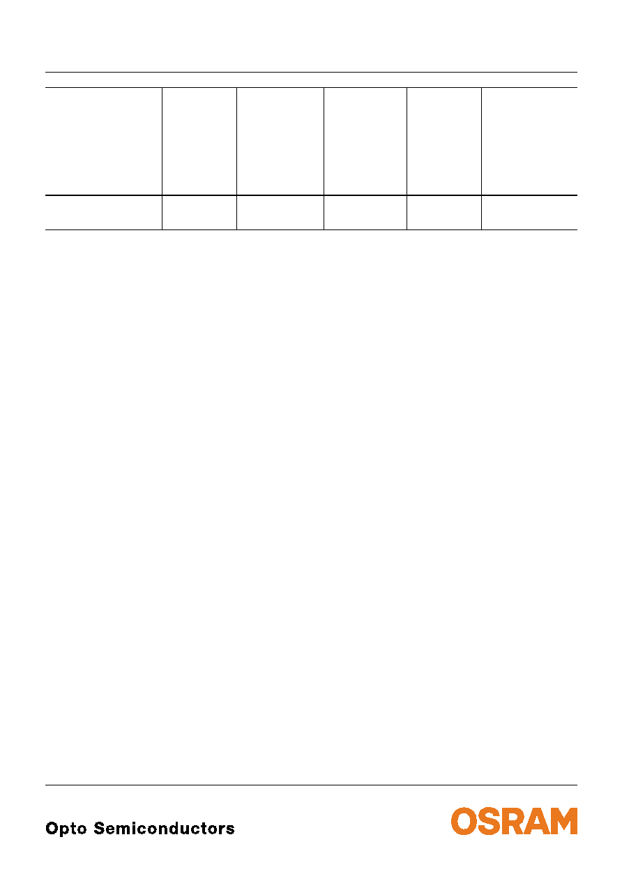
Typ
Type
Emissions-
farbe
Color of
Emission
Farbe der
Lichtaustritts-
fl‰che
Color of the
Light Emitting
Area
Lichtst‰rke
Luminous
Intensity
I
F
= 10 mA
I
V
(mcd)
Lichtstrom
Luminous
Flux
I
F
= 10 mA
V
(mlm)
Bestellnummer
Ordering Code
s
LW A676-M1N1-25
s
LW A676-N1P2-25
white
colored
diffused
18.0 ... 35.5
28.0 ... 71.0
77 (typ.)
140 (typ.)
Q62703Q5105
Q62703Q5106
LW A676
2003-08-28
3
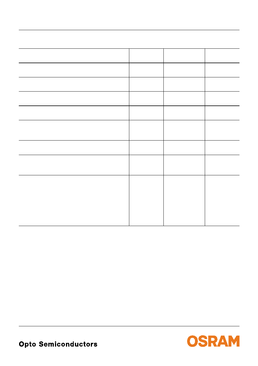
Grenzwerte
Maximum Ratings
Bezeichnung
Parameter
Symbol
Symbol
Wert
Value
Einheit
Unit
Betriebstemperatur
Operating temperature range
T
op
≠ 40 ... + 100
∞C
Lagertemperatur
Storage temperature range
T
stg
≠ 40 ... + 100
∞C
Sperrschichttemperatur
Junction temperature
T
j
+ 100
∞C
Durchlassstrom
Forward current
I
F
20
mA
Stoþstrom
Surge current
t
10
µ
s,
D
= 0.005
I
FM
0.2
A
Sperrspannung
1)
Reverse voltage
V
R
12
V
Leistungsaufnahme
Power consumption
T
A
25 ∞C
P
tot
90
mW
W‰rmewiderstand
Thermal resistance
Sperrschicht/Umgebung
Junction/ambient
Sperrschicht/Lˆtpad
Junction/solder point
Montage auf PC-Board FR 4 (Padgrˆþe
16 mm
2
)
mounted on PC board FR 4 (pad size
16 mm
2
)
R
th JA
R
th JS
530
300
K/W
K/W
1)
f¸r kurzzeitigen Betrieb geeignet / suitable for short term application
2003-08-28
4
LW A676
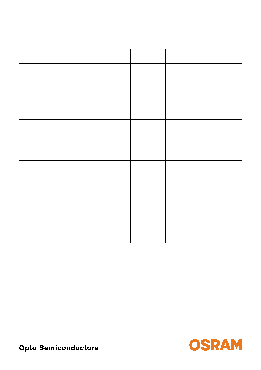
Kennwerte (
T
A
= 25 ∞C)
Characteristics
Bezeichnung
Parameter
Symbol
Symbol
Wert
Value
Einheit
Unit
Farbkoordinate x nach CIE 1931
1)
(typ.)
Chromaticity coordinate x acc. to CIE 1931
I
F
= 10 mA
x
0.30
≠
Farbkoordinate y nach CIE 1931
1)
(typ.)
Chromaticity coordinate y acc. to CIE 1931
I
F
= 10 mA
y
0.32
≠
Abstrahlwinkel bei 50 %
I
V
(Vollwinkel)
(typ.)
Viewing angle at 50 %
I
V
2
120
Grad
deg.
Durchlassspannung
2)
(typ.)
Forward voltage
(max.)
I
F
= 10 mA
V
F
V
F
3.5
4.1
V
V
Sperrstrom
(typ.)
Reverse current
(max.)
V
R
= 12 V
I
R
I
R
0.01
10
µ
A
µ
A
Temperaturkoeffizient von x
(typ.)
Temperature coefficient of y
I
F
= 10 mA; ≠10∞C
T
100∞C
TC
x
0.07
10
-3
/K
Temperaturkoeffizient von y
(typ.)
Temperature coefficient of y
I
F
= 10 mA; ≠10∞C
T
100∞C
TC
y
0.25
10
-3
/K
Temperaturkoeffizient von
V
F
(typ.)
Temperature coefficient of
V
F
I
F
= 10 mA; ≠10∞C
T
100∞C
TC
V
≠ 3.1
mV/K
Optischer Wirkungsgrad
(typ.)
Optical efficiency
I
F
= 10 mA
opt
2
lm/W
1)
Farbortgruppen werden mit einer Stromeinpr‰gedauer von 25 ms und einer Genauigkeit von ±0,01 ermittelt.
Chromaticity coordinate groups are tested at a current pulse duration of 25 ms and a tolerance of ±0.01.
2)
Spannungswerte werden mit einer Stromeinpr‰gedauer von 1 ms und einer Genauigkeit von ±0,1 V ermittelt.
Forward voltage values are tested at a current pulse duration of 1 ms and a tolerance of ±0.1 V.

LW A676
2003-08-28
5
Helligkeitswerte werden mit einer Stromeinpr‰gedauer von 25 ms und einer Genauigkeit von
±
11% ermittelt.
Luminous intensity is tested at a current pulse duration of 25 ms and a tolerance of
±
11%.
Gruppenbezeichnung auf Etikett
Group Name on Label
Beispiel: P2-4
Example: P2-4
1)
Farbortgruppen
Chromaticity coordinate groups
Gruppe
Group
x
y
min.
max.
min.
max.
2
0.280
0.305
0.295
0.325
3
0.290
0.315
0.310
0.340
4
0.295
0.320
0.340
0.370
5
0.305
0.330
0.355
0.385
Helligkeits-Gruppierungsschema
Luminous Intensity Groups
Lichtgruppe
Luminous Intensity Group
Lichtst‰rke
Luminous Intensity
I
V
(mcd)
Lichtstrom
Luminous Flux
V
(mlm)
M1
M2
N1
N2
P1
P2
18.0 ... 22.4
22.4 ... 28.0
28.0 ... 35.5
35.5 ... 45.0
45.0 ... 56.0
56.0 ... 71.0
60 (typ.)
75 (typ.)
95 (typ.)
120 (typ.)
150 (typ.)
190 (typ.)
Lichtgruppe
Luminous intensity group
Halbgruppe
Half group
Farbortgruppe
Chromaticity coordinate group
P
2
4