
LW E67C
Power TOPLED
Æ
Enhanced optical Power LED (ATON
Æ
)
Vorl‰ufige Daten
Preliminary Data
2003-09-12
1
Besondere Merkmale
∑ Geh‰usetyp: weiþes P-LCC-4 Geh‰use
∑ Besonderheit des Bauteils: mehr Licht durch
einen geringen thermischen Widerstand
∑ Farbort: x = 0,32, y = 0,31 nach CIE 1931 (weiþ)
∑ typische Farbtemperatur: 6500 K
∑ Farbwiedergabeindex: 80
∑ Abstrahlwinkel: Lambertscher Strahler (120∞)
∑ Technologie: InGaN
∑ optischer Wirkungsgrad: 12 lm/W
∑ Gruppierungsparameter: Lichtst‰rke,
Farbort, Durchlassspannung
∑ Verarbeitungsmethode: f¸r alle
SMT-Best¸cktechniken geeignet
∑ Lˆtmethode: IR Reflow Lˆten und
Wellenlˆten (TTW)
∑ Vorbehandlung: nach JEDEC Level 2
∑ Gurtung: 8 mm Gurt mit 2000/Rolle, ¯180 mm
oder 8000/Rolle, ¯330 mm
∑ ESD-Festigkeit: ESD-sicher bis 2 kV nach
EOS/ESD-5.1-1993
Anwendungen
∑ Verkehrssignale
∑ Hinterleuchtung (LCD, Schalter, Tasten,
Displays, Werbebeleuchtung,
Allgemeinbeleuchtung)
∑ Innen- und Auþenbeleuchtung im Automobilbe-
reich (z.B. Instrumentenbeleuchtung)
∑ Ersatz von Kleinst-Gl¸hlampen
∑ Leselampen
∑ Rettungsnotleuchten
∑ Signal- und Symbolleuchten
∑ Markierungsbeleuchtung (z.B. Stufen, Flucht-
wege, u.‰.)
∑ Scanner
Features
∑ package: white P-LCC-4 package
∑ feature of the device: more brightness due to
a lower thermal resistance
∑ color coordinates: x = 0.32, y = 0.31 acc. to
CIE 1931 (white)
∑ typ. color temperature: 6500 K
∑ color reproduction index: 80
∑ viewing angle: Lambertian Emitter (120∞)
∑ technology: InGaN
∑ optical efficiency: 12 lm/W
∑ grouping parameter: luminous intensity,
color coordinates, forward voltage
∑ assembly methods: suitable for all
SMT assembly methods
∑ soldering methods: IR reflow soldering and
TTW soldering
∑ preconditioning: acc. to JEDEC Level 2
∑ taping: 8 mm tape with 2000/reel, ¯180 mm
or 8000/reel, ¯330 mm
∑ ESD-withstand voltage: up to 2 kV acc. to
EOS/ESD-5.1-1993
Applications
∑ traffic signals
∑ backlighting (LCD, switches, keys, displays,
illuminated advertising, general lighting)
∑ Interior and exterior automotive lighting
(e.g. dashboard backlighting)
∑ substitution of micro incandescent lamps
∑ reading lamps
∑ emergency lighting
∑ signal and symbol luminaire
∑ marker lights (e.g. steps, exit ways, etc.)
∑ scanners
2003-09-12
2
LW E67C
Anm.: -3C5D-1 Farbselektiert nach Farbortgruppen (siehe Seite 5)
-3C5D-1 gesamter Durchlassspannungsbereich, Lieferung in Einzelgruppen (siehe Seite 6)
Die Standardlieferform von Serientypen beinhaltet eine untere bzw. eine obere Familiengruppe,
die aus nur 3 bzw. 4 Halbgruppen besteht. Einzelne Halbgruppen sind nicht erh‰ltlich.
In einer Verpackungseinheit / Gurt ist immer nur eine Halbgruppe enthalten.
Note: -3C5D-1 color selection acc. to chromaticity coordinate groups (siehe Seite 5)
-3C5D-1 gesamter Durchlassspannungsbereich, delivery in single groups (siehe Seite 6)
The standard shipping format for serial types includes a lower or upper family group of 3 or 4
individual groups. Individual half groups are not available.
No packing unit / tape ever contains more than one luminous intensity half group.
1
Typ
Type
Emissions-
farbe
Color of
Emission
Farbe der
Lichtaustritts-
fl‰che
Color of the
Light Emitting
Area
Lichtst‰rke
Luminous
Intensity
I
F
= 30 mA
I
V
(mcd)
Lichtstrom
Luminous
Flux
I
F
= 30 mA
V
(mlm)
Bestellnummer
Ordering Code
LW E67C-T2U2-3C5D-1
LW E67C-U2V2-3C5D-1
white colored
diffused
355 ... 710
560 ...1120
1600 (typ.)
2500 (typ.)
Q65110A0473
Q65110A0571
LW E67C
2003-09-12
3
Grenzwerte
Maximum Ratings
Bezeichnung
Parameter
Symbol
Symbol
Wert
Value
Einheit
Unit
Betriebstemperatur
Operating temperature range
T
op
≠ 40 ... + 100
∞C
Lagertemperatur
Storage temperature range
T
stg
≠ 40 ... + 100
∞C
Sperrschichttemperatur
Junction temperature
T
j
+ 110
∞C
Durchlassstrom
Forward current
I
F
30
mA
Stoþstrom
Surge current
t
10
µ
s,
D
= 0.1
I
FM
300
mA
Sperrspannung
1)
Reverse voltage
V
R
5
V
Leistungsaufnahme
Power consumption
P
tot
135
mW
W‰rmewiderstand
Thermal resistance
Sperrschicht/Umgebung
Junction/ambient
Sperrschicht/Lˆtpad
Junction/solder point
Montage auf PC-Board FR 4 (Padgrˆþe
16 mm
2
)
mounted on PC board FR 4 (pad size
16 mm
2
)
R
th JA
R
th JS
350
180
K/W
K/W
1)
f¸r kurzzeitigen Betrieb geeignet / suitable for short term application
2003-09-12
4
LW E67C
Kennwerte (
T
A
= 25 ∞C)
Characteristics
Bezeichnung
Parameter
Symbol
Symbol
Wert
Value
Einheit
Unit
Farbkoordinate x nach CIE 1931
1)
(typ.)
Chromaticity coordinate x acc. to CIE 1931
I
F
= 30 mA
x
0.32
≠
Farbkoordinate y nach CIE 1931
1)
(typ.)
Chromaticity coordinate y acc. to CIE 1931
I
F
= 30 mA
y
0.31
≠
Abstrahlwinkel bei 50 %
I
V
(Vollwinkel)
(typ.)
Viewing angle at 50 %
I
V
2
120
Grad
deg.
Durchlassspannung
2)
(min.)
Forward voltage
(typ.)
I
F
= 30 mA
(max.)
V
F
V
F
V
F
3.25
3.9
4.35
V
V
V
Sperrstrom
(typ.)
Reverse current
(max.)
V
R
= 5 V
I
R
I
R
0.01
10
µ
A
µ
A
Temperaturkoeffizient von x
(typ.)
Temperature coefficient of x
I
F
= 30 mA; ≠10∞C
T
100∞C
TC
x
≠0.1
10
-3
/K
Temperaturkoeffizient von y
(typ.)
Temperature coefficient of y
I
F
= 30 mA; ≠10∞C
T
100∞C
TC
y
≠0.2
10
-3
/K
Temperaturkoeffizient von
V
F
(typ.)
Temperature coefficient of
V
F
I
F
= 30 mA; ≠10∞C
T
100∞C
TC
V
≠ 5.0
mV/K
Optischer Wirkungsgrad
(typ.)
Optical efficiency
I
F
= 30 mA
opt
12
lm/W
1)
Farbortgruppen werden mit einer Stromeinpr‰gedauer von 25 ms und einer Genauigkeit von ±0,01 ermittelt.
Chromaticity coordinate groups are tested at a current pulse duration of 25 ms and a tolerance of ±0.01.
2)
Durchlassspannungsgruppen werden mit einer Stromeinpr‰gedauer von 1 ms und einer Genauigkeit von ±0,05 V
ermittelt.
Forward voltage groups are tested at a current pulse duration of 1 ms and a tolerance of ±0.05 V.
LW E67C
2003-09-12
5
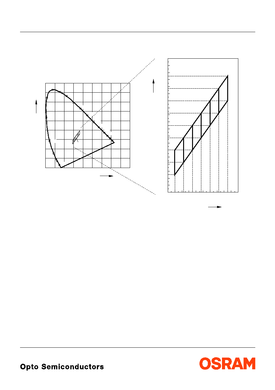
Farbortgruppen
Chromaticity coordinate groups
OHA04327
520
530
540
550
560
570
580
590
600
610
620
630
0
0
0.1
0.2
0.3
0.4
0.5
0.6
0.7
0.8
0.9
0.1
0.2
0.3
0.4
0.5
0.6
0.7
0.8
0.9
510
500
490
480
470
450
460
0.28
0.23
0.24
0.30
0.32
0.34
0.36
0.25
0.26
0.27
0.28
0.29
0.30
0.31
0.32
0.33
0.34
0.35
0.36
0.37
0.38
0.39
0.40
0.42
0.38
+
E
0.29
0.31
0.33
0.35
Cy
0.41
Cx
Cx
0.37
Cy
5C
5D
4D
4C
3D
3C
+
2003-09-12
6
LW E67C
Helligkeitswerte werden mit einer Stromeinpr‰gedauer von 25 ms und einer Genauigkeit von
±
11% ermittelt.
Luminous intensity is tested at a current pulse duration of 25 ms and a tolerance of
±
11%.
Gruppenbezeichnung auf Etikett
Group Name on Label
Beispiel: T2-4D-3
Example: T2-4D-3
2)
Durchlassspannungsgruppen
Forward voltage groups
Gruppe
Group
Durchlassspannung
Forward voltage
Einheit
Unit
min.
max.
3
3.25
3.8
V
4
3.8
4.35
V
Helligkeits-Gruppierungsschema
Luminous Intensity Groups
Lichtgruppe
Luminous Intensity Group
Lichtst‰rke
Luminous Intensity
I
V
(mcd)
Lichtstrom
Luminous Flux
V
(mlm)
T2
U1
U2
V1
V2
355 ... 450
450 ... 560
560 ... 710
710 ... 900
900 ... 1120
1200 (typ.)
1500 (typ.)
1900 (typ.)
2400 (typ.)
3000 (typ.)
Lichtgruppe
Luminous Intensity
Group
Halbgruppe
Half Group
Farbortgruppe
Chromaticity
Coordinate Group
Durchlassspannung
Forward Voltage
T
2
4D
3
LW E67C
2003-09-12
7
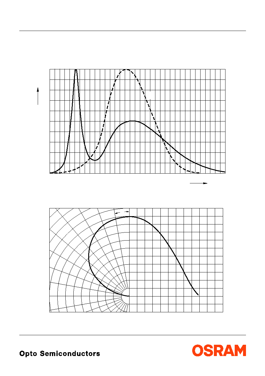
Relative spektrale Emission
I
rel
=
f
(
),
T
A
= 25 ∞C,
I
F
= 30 mA
Relative Spectral Emission
V(
) = spektrale Augenempfindlichkeit
Standard eye response curve
Abstrahlcharakteristik
I
rel
=
f
(
)
Radiation Characteristic
0
400
OHL01461
I
20
40
60
80
%
100
rel
nm
V
450
500
550
600
650
700
750
0
0.2
0.4
1.0
0.8
0.6
1.0
0.8
0.6
0.4
0∞
10∞
20∞
40∞
30∞
OHL01660
50∞
60∞
70∞
80∞
90∞
100∞
0∞
20∞
40∞
60∞
80∞
100∞
120∞
LW E67C
2003-09-12
8
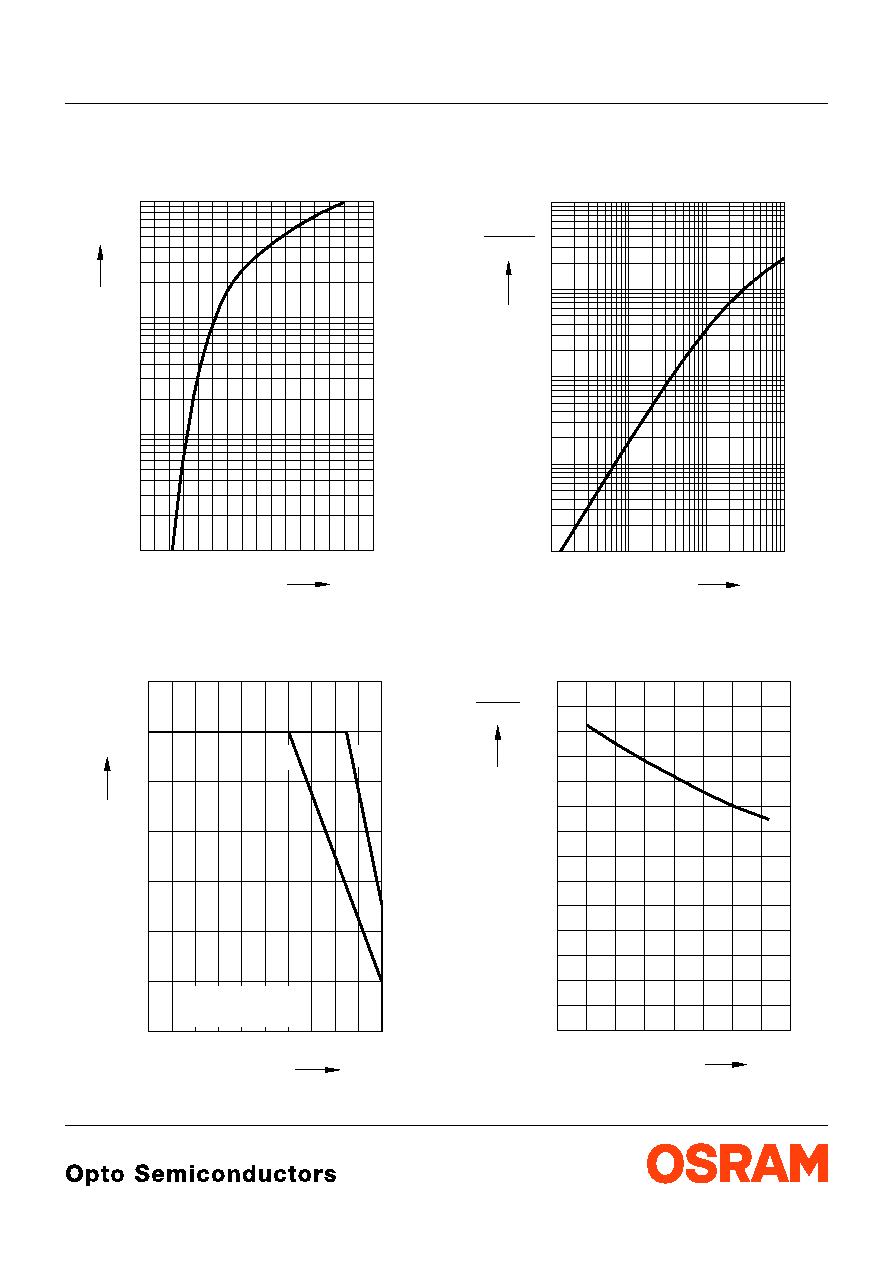
Durchlassstrom
I
F
=
f
(
V
F
)
Forward Current
T
A
= 25 ∞C
Maximal zul‰ssiger Durchlassstrom
I
F
=
f
(
T
)
Max. Permissible Forward Current
Relative Lichtst‰rke
I
V
/
I
V(30 mA)
=
f
(
I
F
)
Relative Luminous Intensity
T
A
= 25 ∞C
Relative Lichtst‰rke
I
V
/
I
V(25 ∞C)
=
f
(
T
A
)
Relative Luminous Intensity
I
F
= 30 mA
OHL11462
2.0
I
F
V
F
2.5 3.0 3.5 4.0 4.5 5.0
V 6.0
5
10
-1
10
0
10
5
1
mA
10
5
2
60
0
0
40
20
F
I
mA
100
80 ∞C
T
OHL21488
5
10
15
20
25
30
35
temp. ambient
A
T
temp. solder point
S
T
A
T
S
T
OHL01497
10
-3
10
-2
10
-1
10
0
10
1
10
-1
10
10
0
1
mA
2
10
F
I
(30 mA)
I
V
I
V
OHL02870
-60
0
T
∞C
V (25 ∞C)
I
I
V
-40 -20
0
20 40 60
100
0.2
0.4
0.6
0.8
1.0
1.2
1.4
LW E67C
2003-09-12
9
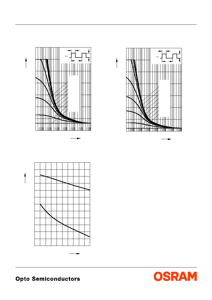
Zul‰ssige Impulsbelastbarkeit
I
F
=
f
(
t
p
)
Permissible Pulse Handling Capability
Duty cycle
D
= parameter,
T
A
= 25 ∞C
Farbortverschiebung
x, y =
f
(
I
F
)
Chromaticity Coordinate Shift
T
A
= 25 ∞C
Zul‰ssige Impulsbelastbarkeit
I
F
=
f
(
t
p
)
Permissible Pulse Handling Capability
Duty cycle
D
= parameter,
T
A
= 85 ∞C
OHL01953
10
-5
p
t
F
I
10
-4
10
-3
10
-2
10
-1
10
0
10
1
0
A
2
10
s
D
t
P
T
=
T
P
t
I
F
0.01
0.05
0.2
0.1
0.005
0.02
0.5
D
=
0.05
0.10
0.15
0.20
0.25
0.35
1
40
OHL01655
0.300
0
10
20
30
x, y
50
mA
x
y
F
I
0.302
0.304
0.306
0.308
0.310
0.312
0.314
0.316
0.318
0.324
OHL01954
10
-5
p
t
F
I
10
-4
10
-3
10
-2
10
-1
10
0
10
1
0
A
2
10
s
D
t
P
T
=
T
P
t
I
F
0.01
0.05
0.2
0.1
0.005
0.02
0.5
D
=
0.05
0.10
0.15
0.20
0.25
0.35
1
2003-09-12
10
LW E67C
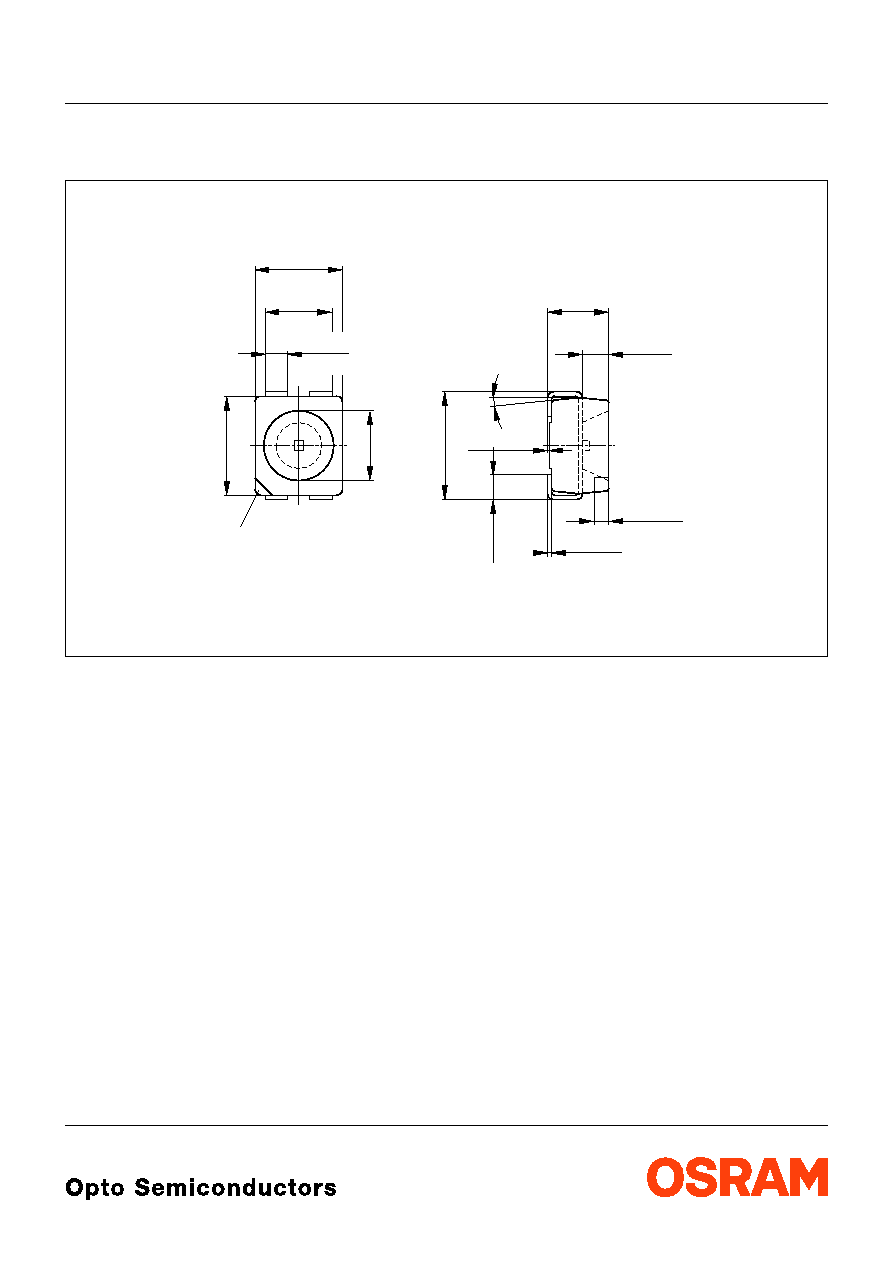
Maþzeichnung
Package Outlines
Maþe werden wie folgt angegeben: mm (inch) / Dimensions are specified as follows: mm (inch).
Gewicht / Approx. weight: 35 mg
marking
Package
4
∞
±1
GPLY6991
A
C
C
C
0.8 (0.031)
0.6 (0.024)
2.6 (0.102)
2.1 (0.083)
2.3 (0.091)
3.0 (0.118)
3.4 (0.134)
3.0 (0.118)
(2.4 (0.094))
0.5 (0.020)
1.1 (0.043)
3.7 (0.146)
3.3 (0.130)
0.12 (0.005)
0.18 (0.007)
0.1 (0.004) typ
0.4 (0.016)
0.6 (0.024)
0.9 (0.035)
0.7 (0.028)
2.1 (0.083)
1.7 (0.067)
LW E67C
2003-09-12
11
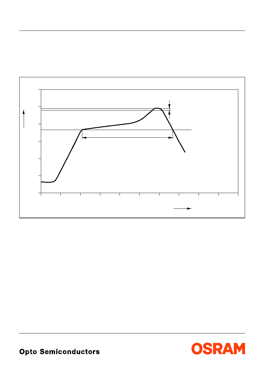
Lˆtbedingungen
Vorbehandlung nach JEDEC Level 2
Soldering Conditions Preconditioning acc. to JEDEC Level 2
IR-Reflow Lˆtprofil
(nach IPC 9501)
IR Reflow Soldering Profile
(acc. to IPC 9501)
OHLY0597
0
0
50
100
150
200
250
50
100
150
200
250
300
T
t
∞C
s
240-245 ∞C
10-40 s
183 ∞C
120 to 180 s
Defined for Preconditioning: up to 6 K/s
Ramp-down rate up to 6 K/s
Ramp-up rate up to 6 K/s
Defined for Preconditioning: 2-3 K/s
2003-09-12
12
LW E67C
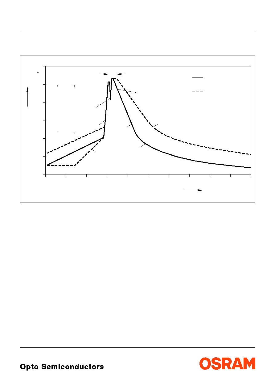
Wellenlˆten (TTW)
(nach CECC 00802)
TTW Soldering
(acc. to CECC 00802)
OHLY0598
0
0
50
100
150
200
250
50
100
150
200
250
300
T
t
C
s
235 C
10 s
C
... 260
1. Welle
1. wave
2. Welle
2. wave
5 K/s
2 K/s
ca 200 K/s
C
C
... 130
100
2 K/s
Zwangsk¸hlung
forced cooling
Normalkurve
standard curve
Grenzkurven
limit curves
LW E67C
2003-09-12
13
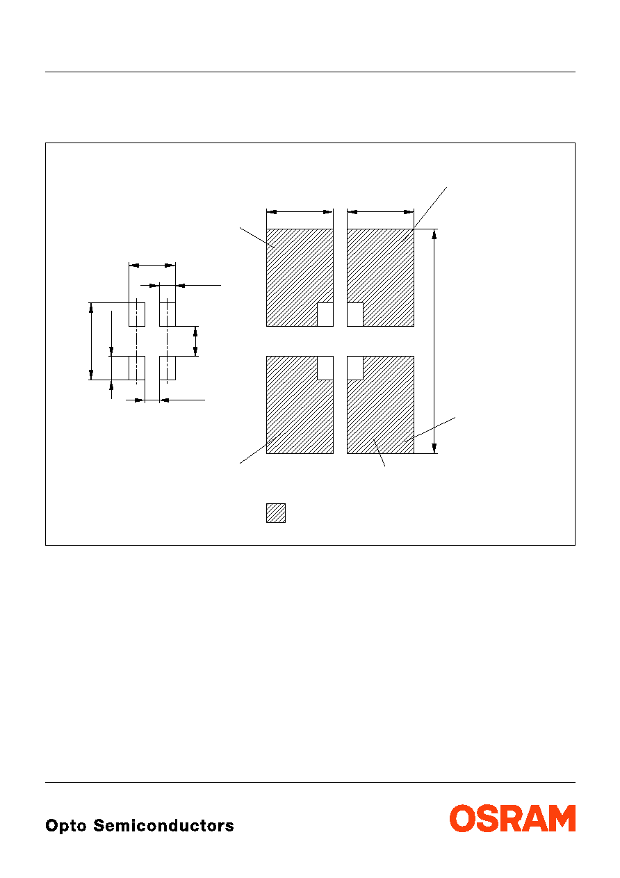
Empfohlenes Lˆtpaddesign verwendbar f¸r TOPLED
Æ
und Power TOPLED
Æ
IR Reflow Lˆten
Recommended Solder Pad useable for TOPLED
Æ
and Power TOPLED
Æ
IR Reflow Soldering
Maþe werden wie folgt angegeben: mm (inch) / Dimensions are specified as follows: mm (inch)
OHLPY440
Padgeometrie f¸r
verbesserte W‰rmeableitung
improved heat dissipation
Paddesign for
Lˆtstoplack
Solder resist
0.8 (0.031)
3.7 (0.146)
1.1 (0.043)
2.3 (0.091)
3.3 (0.130)
1.5 (0.059)
11.1 (0.437)
Cu Fl‰che / 16 mm per pad
2
Cu-area
_
<
3.3 (0.130)
Kathode/
Cathode
Anode
Fl‰che darf elektrisch nicht beschaltet werden.
Do not use this area for electrical contact.
0.7 (0.028)
Fl‰che darf elektrisch nicht beschaltet werden.
Do not use this area for electrical contact.
2003-09-12
14
LW E67C
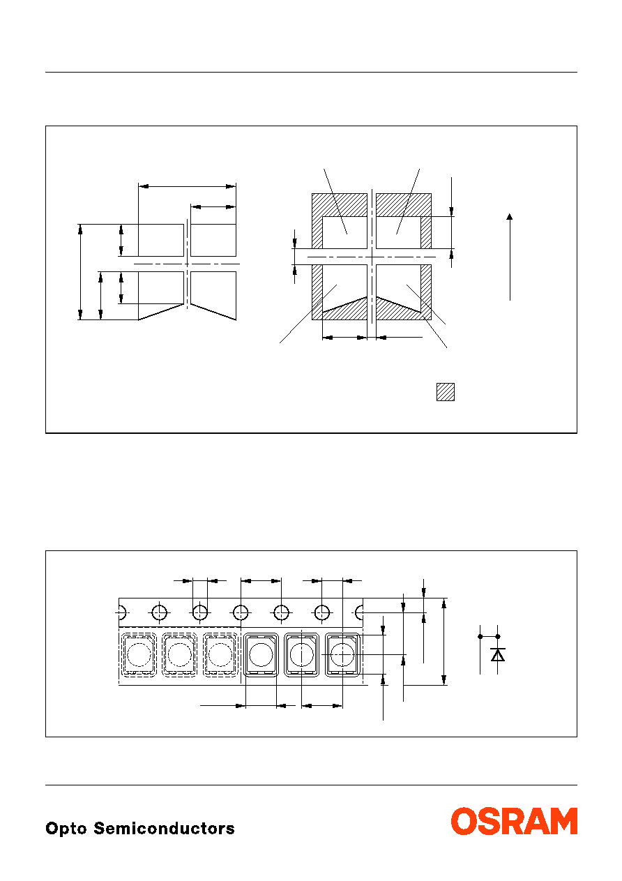
Empfohlenes Lˆtpaddesign
Wellenlˆten (TTW)
Recommended Solder Pad
TTW Soldering
Maþe werden wie folgt angegeben: mm (inch) / Dimensions are specified as follows: mm (inch)
Gurtung / Polarit‰t und Lage
Verpackungseinheit 2000/Rolle, ¯180 mm
oder 8000/Rolle, ¯330 mm
Method of Taping / Polarity and Orientation Packing unit 2000/reel, ¯180 mm
or 8000/reel, ¯330 mm
Maþe werden wie folgt angegeben: mm (inch) / Dimensions are specified as follows: mm (inch)
OHAY1583
6.1 (0.240)
2.8 (0.110)
2 (0.079)
3 (0.118)
6 (0.236)
2 (0.079)
1 (0.039)
2.8 (0.110)
0.5 (0.020)
Solder resist
Lˆtstoplack
PCB-direction
Bewegungsrichtung
der Platine
2 (0.079)
Padgeometrie f¸r
improved heat dissipation
verbesserte W‰rmeableitung
Paddesign for
2
Cu Fl‰che / > 16 mm per pad
Cu-area
Anode
Fl‰che darf elektrisch nicht beschaltet werden.
Do not use this area for electrical contact.
Fl‰che darf elektrisch nicht beschaltet werden.
Do not use this area for electrical contact.
Cathode
Kathode/
OHAY0536
C
C
C
A
4 (0.157)
2.9 (0.114)
1.5 (0.059)
4 (0.157)
3.6 (0.142)
3.5 (0.138)
2 (0.079)
1.75 (0.069)
8 (0.315)
LW E67C
2003-09-12
15
Revision History: 2003-09-12
Date of change
Previous Version:
2003-08-18
Page
Subjects (major changes since last revision)
9
Zul‰ssige Impulsbelastbarkeit / Permissible Pulse Handling Capability
4
value (forward voltage)
8
diagram luminous intensity OHL01462 to OHL11462
8
diagram max. permissible forward current OHL01489 to OHL11489
9
diagram permissible pulse handling capability OHL01580/01579 to
OHL11578/11579
2, 5
color coordinate grouping for white
8
Max. Permissible Forward Current
15
annotations
2002-07-25
13
new IR solder pad (OHLPY439 to OHLPY440)
2002-08-05
3
reverse voltage (footnote)
2002-08-21
2, 5
new luminous intensity groups and new ordering codes
2002-10-25
1, 2, 5
new grouping parameter: forward voltage
2002-11-08
15
new patent no.
2003-03-04
all
PCN data sheet
2003-03-31
14
new recommended solder pad
2003-05-26
8
new diagram permissible forward current
2003-06-02
9
new diagrams pulse derating
2003-06-30
2003-09-12
16
LW E67C
Published by OSRAM Opto Semiconductors GmbH
Wernerwerkstrasse 2, D-93049 Regensburg
© All Rights Reserved.
Attention please!
The information describes the type of component and shall not be considered as assured characteristics.
All typical data and graphs are basing on representative samples, but don't represent the production range. If requested,
e.g. because of technical improvements, these typ. data will be changed without any further notice.
Terms of delivery and rights to change design reserved. Due to technical requirements components may contain
dangerous substances. For information on the types in question please contact our Sales Organization.
If printed or downloaded, please find the latest version in the Internet.
Packing
Please use the recycling operators known to you. We can also help you ≠ get in touch with your nearest sales office.
By agreement we will take packing material back, if it is sorted. You must bear the costs of transport. For packing
material that is returned to us unsorted or which we are not obliged to accept, we shall have to invoice you for any costs
incurred.
Components used in life-support devices or systems must be expressly authorized for such purpose! Critical
components
1
may only be used in life-support devices or systems
2
with the express written approval of OSRAM OS.
1
A critical component is a component used in a life-support device or system whose failure can reasonably be expected
to cause the failure of that life-support device or system, or to affect its safety or the effectiveness of that device or
system.
2
Life support devices or systems are intended (a) to be implanted in the human body, or (b) to support and/or maintain
and sustain human life. If they fail, it is reasonable to assume that the health of the user may be endangered.
Patent List
Patent No.
US 6 066 861, US 6 277 301, US 6 245 259