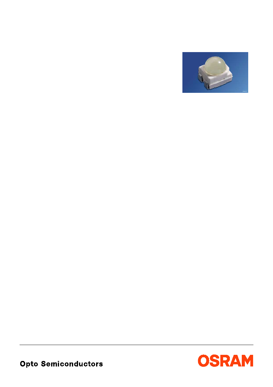
LS E655, LA E655, LY E655
Power TOPLED
ģ
with Lens
High-optical Power LED (HOP)
Vorlšufige Daten / Preliminary Data
2003-12-17
1
Besondere Merkmale
∑
Gehšusetyp: weiŖes P-LCC-4-Gehšuse,
farbloser klarer Verguss
∑
Besonderheit des Bauteils: fokussierte
Abstrahlung in SMT-Technologie; hohe Helligkeit
in Achsrichtung
∑
Wellenlšnge: 633 nm (super-rot),
617 nm (amber), 587 nm (gelb)
∑
Abstrahlwinkel: 60į
∑
Technologie: InGaAlP
∑
optischer Wirkungsgrad: 12 lm/W (super-rot),
15 lm/W (amber); 16 lm/W (gelb)
∑
Gruppierungsparameter: Lichtstšrke,
Durchflussspannung, Wellenlšnge
∑
Verarbeitungsmethode: fŁr alle
SMT-BestŁcktechniken geeignet
∑
LŲtmethode: IR Reflow LŲten und
WellenlŲten (TTW)
∑
Vorbehandlung: nach JEDEC Level 2
∑
Gurtung: 12 mm Gurt mit 2000/Rolle, Ý330 mm
∑
ESD-Festigkeit: ESD-sicher bis 2 kV nach
JESD22-A114-B
Anwendungen
∑
Ampelanwendung
∑
Hinterleuchtung (LCD, Schalter, Tasten, Displays,
Werbebeleuchtung)
∑
Innen- und AuŖenbeleuchtung im
Automobilbereich (z.B. Instrumenten-
beleuchtung, Blinker, seitl. Begrenzungs-
leuchten, Bremslichter)
∑
Ersatz von Kleinst-GlŁhlampen
∑
Markierungsbeleuchtung (z.B. Stufen,
Fluchtwege, u.š.)
∑
Signal- und Symbolleuchten
Features
∑
package: white P-LCC-4 package, colorless clear
resin
∑
feature of the device: focussed radiation in
SMT technology; high brightness in beam
direction
∑
wavelength: 633 nm (super-red),
617 nm (amber), 587 nm (yellow)
∑
viewing angle: 60į
∑
technology: InGaAlP
∑
optical efficiency: 12 lm/W (super-red),
15 lm/W (amber); 16 lm/W (yellow)
∑
grouping parameter: luminous intensity,
forward voltage, wavelength
∑
assembly methods: suitable for all
SMT assembly methods
∑
soldering methods: IR reflow soldering and
TTW soldering
∑
preconditioning: acc. to JEDEC Level 2
∑
taping: 12 mm tape with 2000/reel, Ý330 mm
∑
ESD-withstand voltage: up to 2 kV acc. to
JESD22-A114-B
Applications
∑
traffic lights
∑
backlighting (LCD, switches, keys, displays,
illuminated advertising)
∑
interior and exterior automotive lighting
(e.g. dashboard backlighting, turn signal lamps,
sidemarkers, brake lights)
∑
substitution of micro incandescent lamps
∑
marker lights (e.g. steps, exit ways, etc.)
∑
signal and symbol luminaire
2003-12-17
2
LS E655, LA E655, LY E655
Anm.: -1-1
Gesamter Farbbereich (siehe Seite 4)
-26-1 Gesamter Farbbereich, Lieferung in Einzelgruppen (siehe Seite 5)
-1-1
Gesamter Durchlassspannungsbereich, Lieferung in Einzelgruppen (siehe Seite 4)
-26-1 Gesamter Durchlassspannungsbereich, Lieferung in Einzelgruppen (siehe Seite 5)
Note: -1-1
Total color tolerance range (see page 4)
-26-1 Total color tolerance range, delivery in single groups (see page 5)
-1-1
Total forward voltage tolerance, delivery in single groups (see page 4)
-26-1 Total forward voltage tolerance, delivery in single groups (see page 5)
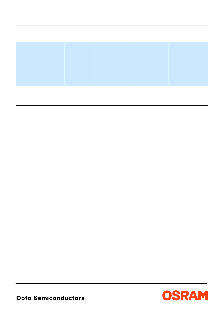
Bestellinformation
Ordering Information
Typ
Type
Emissions-
farbe
Color of
Emission
Lichtstšrke
1)
Seite 13
Luminous
Intensity
1) page 13
I
F
= 50 mA
I
V
(mcd)
Lichtstrom
2)
Seite 13
Luminous Flux
2)
page 13
I
F
= 50 mA
V
(mlm)
Bestellnummer
Ordering Code
LS E655-V1AB-1-1
super-red
710 ... 1800
1200 (typ.)
Q65110A0641
LA E655-V2AB-24-1
LA E655-ABCA-24-1
amber
900 ... 1800
1400 ... 3550
1260 (typ.)
2300 (typ.)
Q62703Q5837
Q62703Q5838
LY E655-V2AB-26-1
LY E655-ABCA-26-1
yellow
900 ... 1800
1400 ... 3550
1260 (typ.)
2300 (typ.)
Q62703Q5912
Q62703Q5913
LS E655, LA E655, LY E655
2003-12-17
3
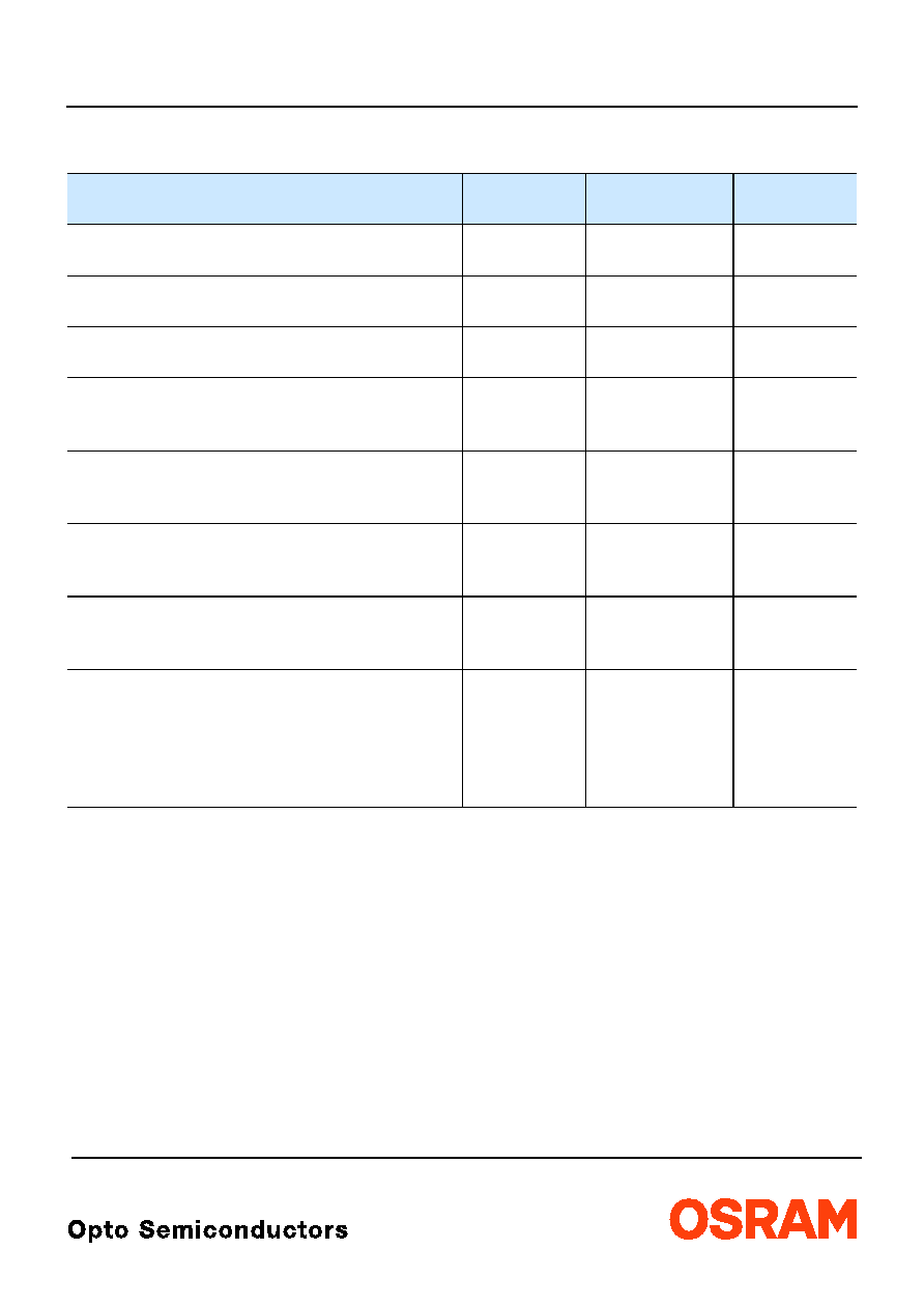
Grenzwerte
Maximum Ratings
Bezeichnung
Parameter
Symbol
Symbol
Wert
Value
Einheit
Unit
Betriebstemperatur
Operating temperature range
T
op
≠ 40 ... + 100
įC
Lagertemperatur
Storage temperature range
T
stg
≠ 40 ... + 100
įC
Sperrschichttemperatur
Junction temperature
T
j
+ 125
įC
Durchlassstrom
Forward current
(
T
A
=25įC)
I
F
70
mA
StoŖstrom
Surge current
t
10
Ķ
s, D = 0.1,
T
A
=25įC
I
FM
0.1
A
Sperrspannung
3)
Seite 13
Reverse voltage
3) page 13
(
T
A
=25įC)
V
R
5
V
Leistungsaufnahme
Power consumption
(
T
A
=25įC)
P
tot
180
mW
Wšrmewiderstand
Thermal resistance
Sperrschicht/Umgebung
4)
Seite 13
Junction/ambient
4) page 13
Sperrschicht/LŲtpad
Junction/soldering point
R
th JA
R
th JS
300
130
K/W
K/W
2003-12-17
4
LS E655, LA E655, LY E655
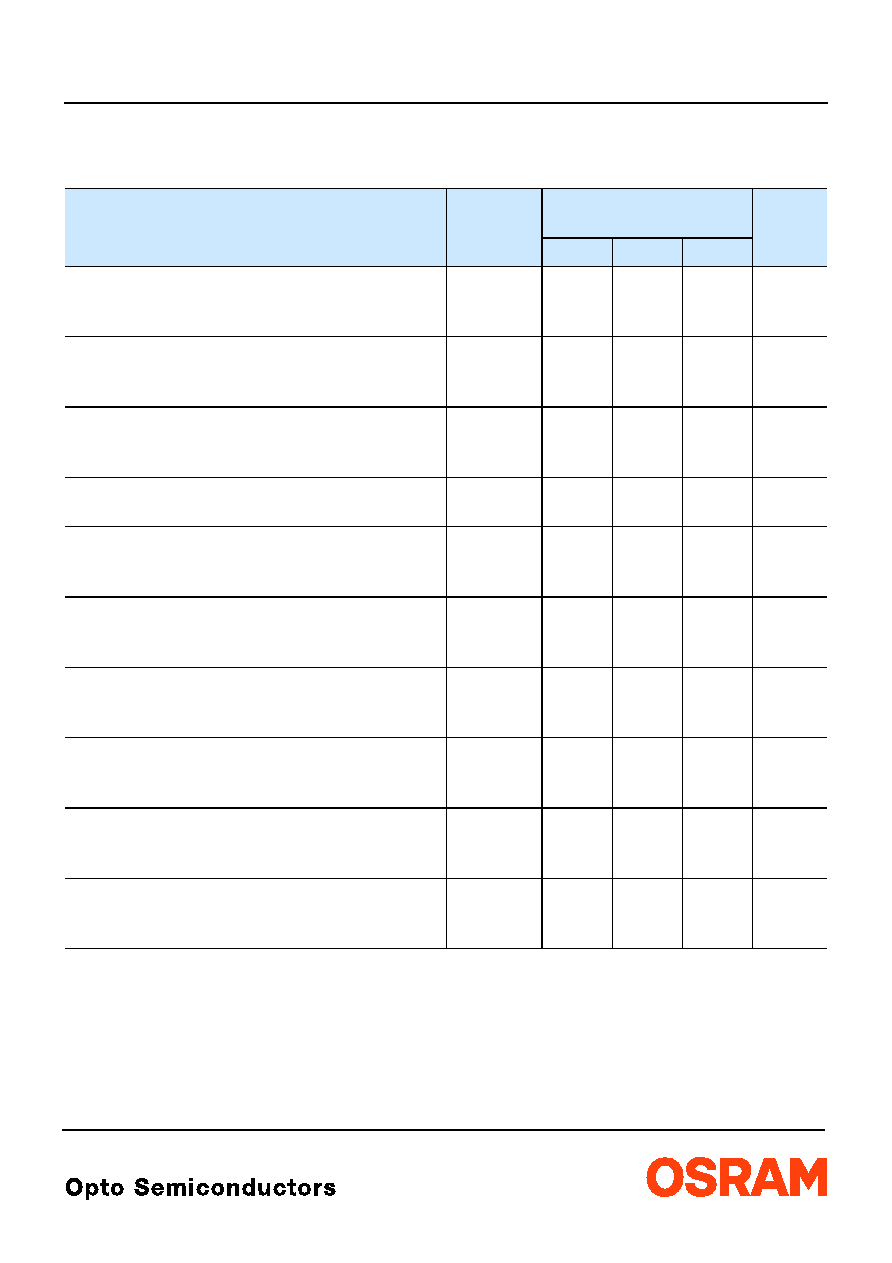
Kennwerte
Characteristics
(
T
A
= 25 įC)
Bezeichnung
Parameter
Symbol
Symbol
Werte
Values
Einheit
Unit
LS
LA
LY
Wellenlšnge des emittierten Lichtes
(typ.)
Wavelength at peak emission
I
F
= 50 mA
peak
645
624
594
nm
Dominantwellenlšnge
5)
Seite 13
Dominant wavelength
5) page 13
I
F
= 50 mA
dom
633
Ī 6
617*
≠5/+7
587*
≠7/+8
nm
Spektrale Bandbreite bei 50 %
I
rel max
(typ.)
Spectral bandwidth at 50 %
I
rel max
I
F
= 50 mA
18
18
15
nm
Abstrahlwinkel bei 50 %
I
V
(Vollwinkel)
(typ.)
Viewing angle at 50 %
I
V
2
60
60
60
Grad
deg.
Durchlassspannung
6)
Seite 13
(min.)
Forward voltage
6) page 13
(typ.)
I
F
= 50 mA
(max.)
V
F
V
F
V
F
1.9*
2.1
2.5
1.9*
2.1
2.5
1.9*
2.1
2.5
V
V
V
Sperrstrom
(typ.)
Reverse current
(max.)
V
R
= 5 V
I
R
I
R
0.01
10
0.01
10
0.01
10
Ķ
A
Ķ
A
Temperaturkoeffizient von
peak
(typ.)
Temperature coefficient of
peak
I
F
= 50 mA; ≠10įC
T
100įC
TC
peak
0.15
0.15
0.13
nm/K
Temperaturkoeffizient von
dom
(typ.)
Temperature coefficient of
dom
I
F
= 50 mA; ≠10įC
T
100įC
TC
dom
0.05
0.08
0.10
nm/K
Temperaturkoeffizient von
V
F
(typ.)
Temperature coefficient of
V
F
I
F
= 50 mA; ≠10įC
T
100įC
TC
V
≠ 3.4
≠ 1.7
≠ 1.8
mV/K
Optischer Wirkungsgrad
(typ.)
Optical efficiency
I
F
= 50 mA
opt
12
15
16
lm/W
* Einzelgruppen siehe Seite 5
Individual groups on page 5

LS E655, LA E655, LY E655
2003-12-17
5
Wellenlšngengruppen (Dominantwellenlšnge)
5)
Seite 13
Wavelength Groups (Dominant Wavelength)
5) page 13
Gruppe
Group
amber
yellow
Einheit
Unit
min.
max.
min.
max.
2
612
616
580
583
nm
3
616
620
583
586
nm
4
620
624
586
589
nm
5
589
592
nm
6
592
595
nm
Durchlassspannungsgruppen
6)
Seite 13
Forward Voltage Groups
6) page 13
Gruppe
Group
super-rot / gelb
super-red / yellow
Einheit
Unit
Gruppe
Group
amber
amber
Einheit
Unit
min.
max.
min.
max.
3
1.9
2.2
V
3A
1.90
2.05
V
4
2.2
2.5
V
3B
2.05
2.20
V
4A
2.20
2.35
V
4B
2.35
2.50
V
Helligkeits-Gruppierungsschema
Brightness Groups
Helligkeitshalbgruppe
Brightness Half Group
Lichtstšrke
1)
Seite 13
Luminous Intensity
1) page 13
I
V
(mcd)
Lichtstrom
2)
Seite 13
Luminous Flux
2) page 13
V
(mlm)
V1
V2
AA
AB
BA
BB
CA
710 ...
900
900 ... 1120
1120 ... 1400
1400 ... 1800
1800 ... 2240
2240 ... 2800
2800 ... 3550
960 (typ.)
1200 (typ.)
1500 (typ.)
1900 (typ.)
2400 (typ.)
3000 (typ.)
3700 (typ.)
Anm.:
Die Standardlieferform von Serientypen beinhaltet eine Familiengruppe. Diese besteht aus 4 Helligkeitshalbgruppen. Einzelne
Helligkeitshalbgruppen sind nicht bestellbar.
Note:
The standard shipping format for serial types includes a family group of 4 individual brightness half groups. Individual brightness
half groups cannot be ordered.
Gruppenbezeichnung auf Etikett
Group Name on Label
Beispiel: AB-23
Example: AB-23
Helligkeitshalbgruppe
Brightness Half Group
Wellenlšnge
Wavelength
Durchlassspannung
Forward Voltage
AB
2
3
Anm.:
In einer Verpackungseinheit / Gurt ist immer nur eine Gruppe fŁr jede Selektion enthalten.
Note:
No packing unit / tape ever contains more than one group for each selection.
2003-12-17
6
LS E655, LA E655, LY E655
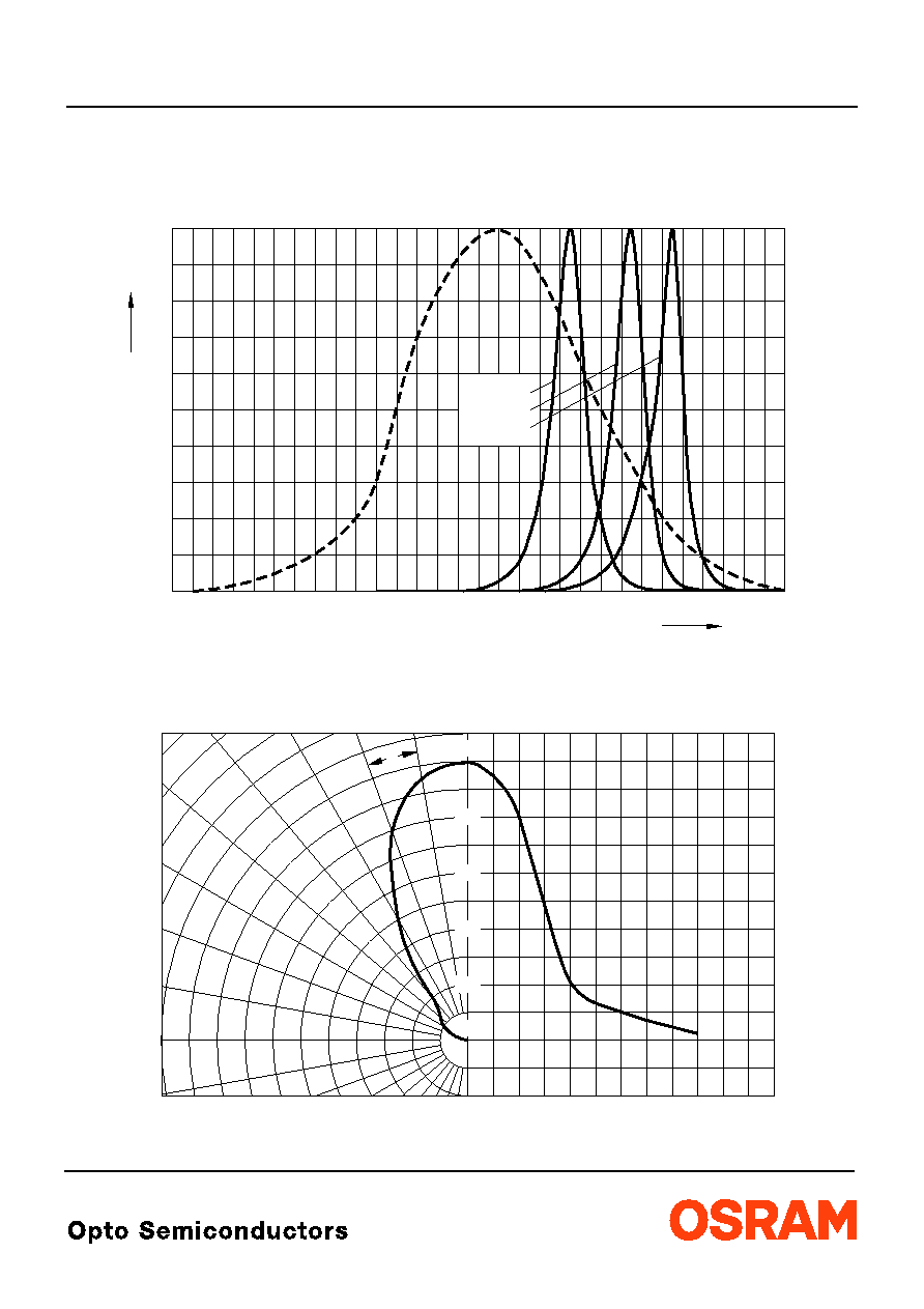
Relative spektrale Emission
2)
Seite 13
Relative Spectral Emission
2) page 13
V(
) = spektrale Augenempfindlichkeit / Standard eye response curve
I
rel
=
f
(
);
T
A
= 25 įC;
I
F
= 50 mA
Abstrahlcharakteristik
2)
Seite 13
Radiation Characteristic
2) page 13
I
rel
=
f
(
);
T
A
= 25 įC
OHL00585
400
0
20
40
60
80
100
450
500
550
600
650
700
nm
%
rel
V
yellow
amber
super-red
OHL00732
0į
20į
40į
60į
80į
100į
120į
0.4
0.6
0.8
1.0
100į
90į
80į
70į
60į
50į
0į
10į
20į
30į
40į
0
0.2
0.4
0.6
0.8
1.0
LS E655, LA E655, LY E655
2003-12-17
7
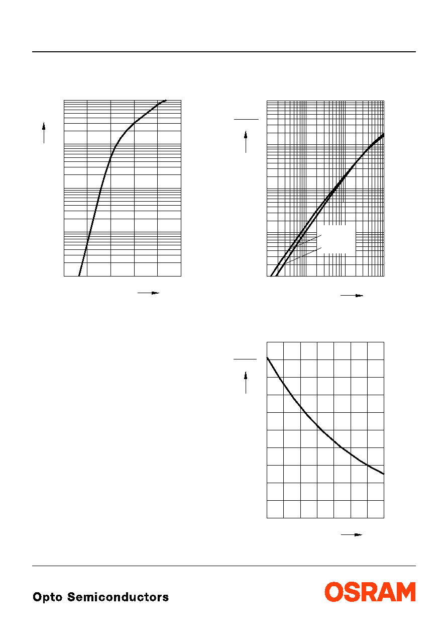
Durchlassstrom
2)
Seite 13
Forward Current
2) page 13
I
F
=
f
(
V
F
);
T
A
= 25 įC
Relative Lichtstšrke
2) 7)
Seite 13
Relative Luminous Intensity
2) 7) page 13
I
V
/
I
V(50 mA)
=
f
(
I
F
);
T
A
= 25 įC
Relative Lichtstšrke
2)
Seite 13
Relative Luminous Intensity
2) page 13
I
V
/
I
V(25 įC)
=
f
(
T
A
);
I
F
= 50 mA
OHL00444
1.4
mA
10
1
10
5
-2
5
0
10
-1
5
10
V
10
2
F
I
F
V
1.6
1.8
2.0
2.2
2.4
V
V (50 mA)
10
-1
0
10
10
1
2
10
mA
10
-3
5
OHL00584
F
I
5
-2
10
5
-1
10
0
10
1
10
I
I
5
5
super-red,
amber
yellow
OHL00740
0
-40
įC
T
(25 įC)
I
V
I
V
0.2
0.4
0.6
0.8
1.0
1.2
1.4
1.6
2.0
-20
0
20
40
60
100
LS E655, LA E655, LY E655
2003-12-17
8
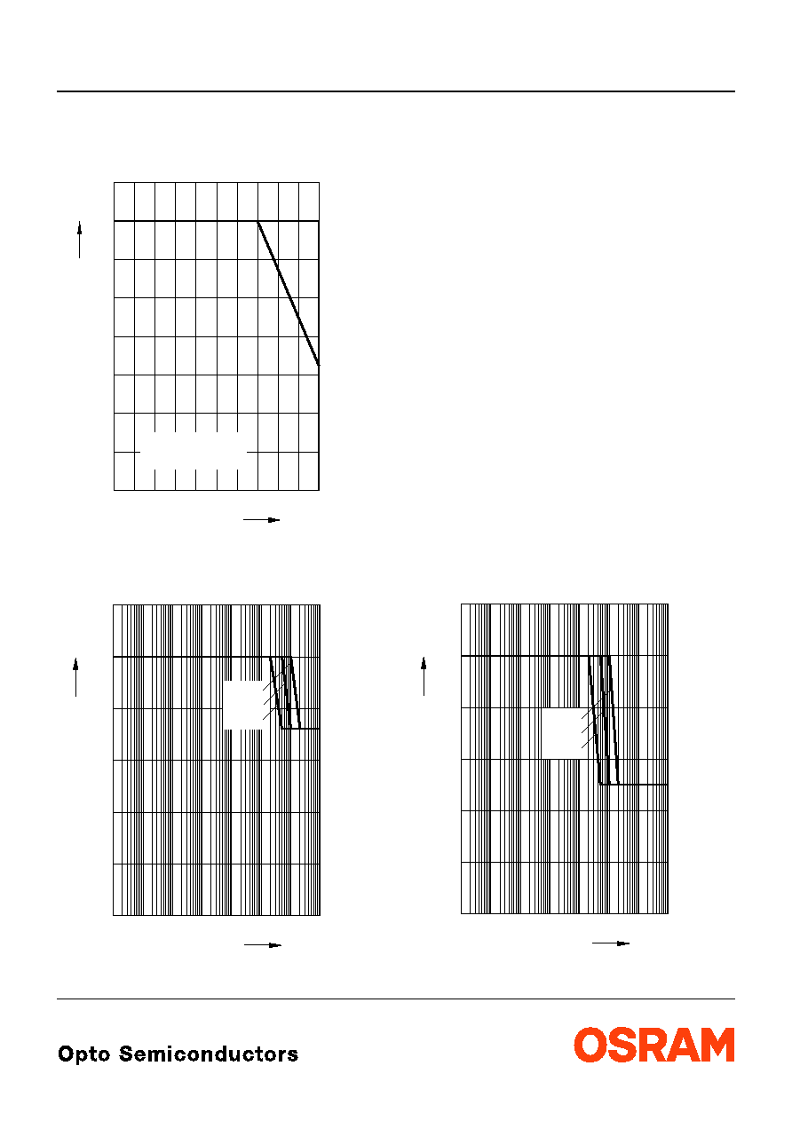
Maximal zulšssiger Durchlassstrom
Max. Permissible Forward Current
I
F
=
f
(
T
)
Zulšssige Impulsbelastbarkeit
I
F
=
f
(
t
p
)
Permissible Pulse Handling Capability
Duty cycle
D
= parameter,
T
A
= 25 įC
Zulšssige Impulsbelastbarkeit
I
F
=
f
(
t
p
)
Permissible Pulse Handling Capability
Duty cycle
D
= parameter,
T
A
= 85 įC
OHL01413
0
0
20
40
60
80 įC 100
T
I
F
20
40
60
80
mA
A
T
S
T
temp. ambient
temp. solder point
A
S
10
30
70
50
OHL01505
F
I
0
0.02
0.04
0.06
0.08
0.1
0.12
A
p
t
-5
10
-4
10
-3
10
-2
10
-1
10
0
10
1
10
2
10
0.005
0.05
0.5
s
OHL01506
F
I
0
0.02
0.04
0.06
0.08
0.10
0.12
A
p
t
-5
10
-4
10
-3
10
-2
10
-1
10
0
10
1
10
2
10
0.005
0.05
0.5
s

LS E655, LA E655, LY E655
2003-12-17
9
MaŖzeichnung
8)
Seite 13
Package Outlines
8) page 13
Gewicht / Approx. weight:
38 mg
Gurtung / Polaritšt und Lage
8)
Seite 13
Verpackungseinheit 2000/Rolle, Ý330 mm
Method of Taping / Polarity and Orientation
8) page 13
Packing unit 2000/reel, Ý330 mm
3.5 (0.138) max.
Ý
2.55 (0.100)
0.13 (0.005)
0.18 (0.007)
0.1 (0.004) typ
marking
Package
1.1 (0.043)
0.5 (0.020)
2.6 (0.102)
3.4 (0.134)
3.0 (0.118)
2.1 (0.083)
2.3 (0.091)
3.0 (0.118)
3.7 (0.146)
3.3 (0.130)
4
į
Ī1
GPLY7000
0.4 (0.016)
0.6 (0.024)
0.9 (0.035)
0.7 (0.028)
1.7 (0.067)
2.1 (0.083)
0.6 (0.024)
0.8 (0.031)
A
C
C
C
Ý
2.60 (0.102)
OHAY0734
C
A
C
C
1.5 (0.059)
2 (0.079)
4 (0.157)
3 (0.118)
3.8 (0.150)
5.5 (0.217)
1.75 (0.069)
12 (0.472)
8 (0.315)

2003-12-17
10
LS E655, LA E655, LY E655
Empfohlenes LŲtpaddesign verwendbar fŁr TOPLED
ģ
und Power TOPLED
ģ
IR Reflow LŲten
8)
Seite 13
Recommended Solder Pad useable for TOPLED
ģ
and Power TOPLED
ģ
IR Reflow Soldering
8) page 13
Empfohlenes LŲtpaddesign
8)
Seite 13
WellenlŲten (TTW)
Recommended Solder Pad
8) page 13
TTW Soldering
OHLPY440
Padgeometrie fŁr
verbesserte Wšrmeableitung
improved heat dissipation
Paddesign for
LŲtstoplack
Solder resist
0.8 (0.031)
3.7 (0.146)
1.1 (0.043)
2.3 (0.091)
3.3 (0.130)
1.5 (0.059)
11.1 (0.437)
Cu Flšche / 16 mm per pad
2
Cu-area
_
<
3.3 (0.130)
Kathode/
Cathode
Anode
Flšche darf elektrisch nicht beschaltet werden.
Do not use this area for electrical contact.
0.7 (0.028)
Flšche darf elektrisch nicht beschaltet werden.
Do not use this area for electrical contact.
OHAY1583
6.1 (0.240)
2.8 (0.110)
2 (0.079)
3 (0.118)
6 (0.236)
2 (0.079)
1 (0.039)
2.8 (0.110)
0.5 (0.020)
Solder resist
LŲtstoplack
PCB-direction
Bewegungsrichtung
der Platine
2 (0.079)
Padgeometrie fŁr
improved heat dissipation
verbesserte Wšrmeableitung
Paddesign for
2
Cu Flšche / > 16 mm per pad
Cu-area
Anode
Flšche darf elektrisch nicht beschaltet werden.
Do not use this area for electrical contact.
Flšche darf elektrisch nicht beschaltet werden.
Do not use this area for electrical contact.
Cathode
Kathode/
LS E655, LA E655, LY E655
2003-12-17
11
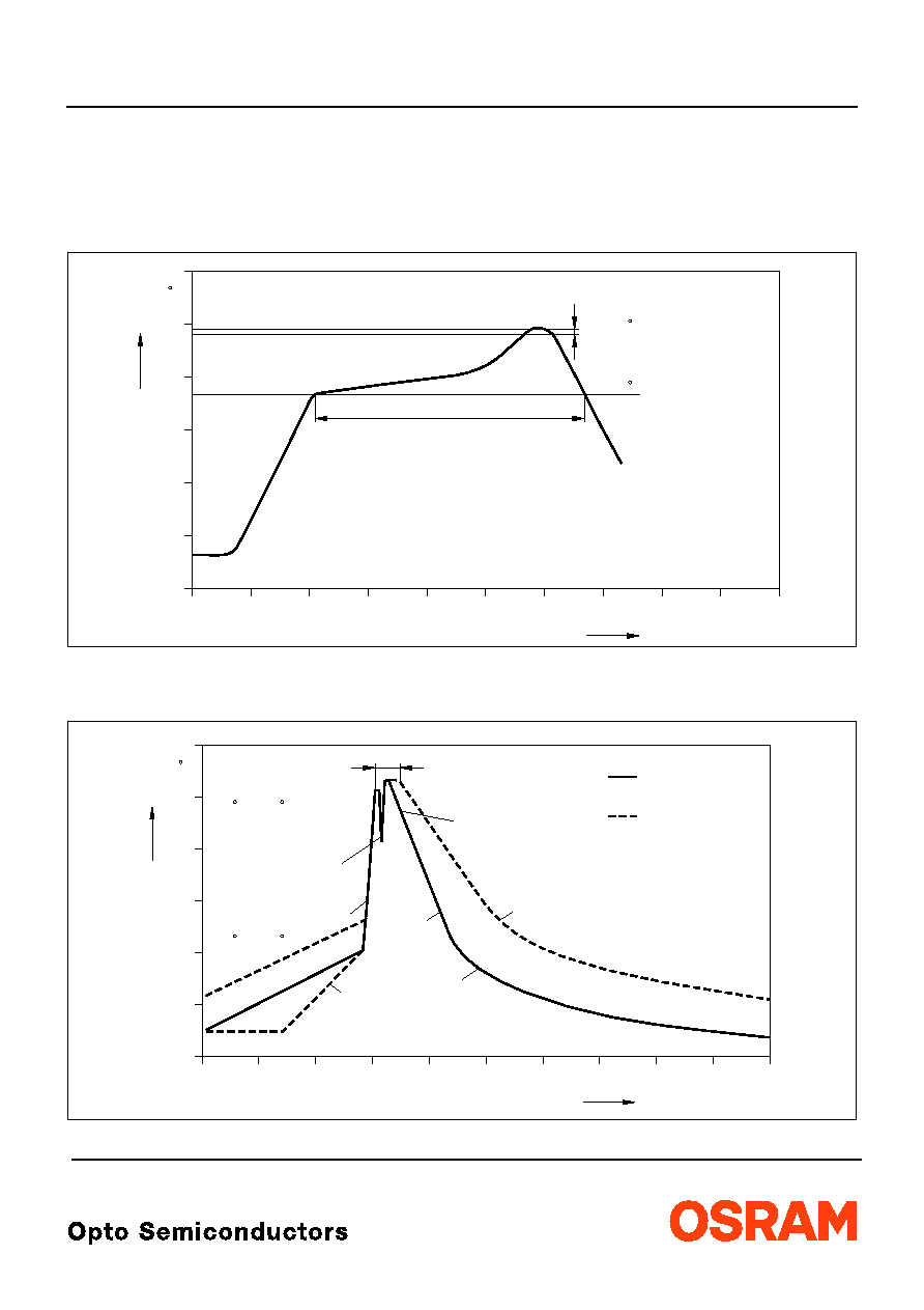
LŲtbedingungen
Vorbehandlung nach JEDEC Level 2
Soldering Conditions
Preconditioning acc. to JEDEC Level 2
IR-Reflow LŲtprofil
(nach IPC 9501)
IR Reflow Soldering Profile
(acc. to IPC 9501)
WellenlŲten (TTW)
(nach CECC 00802)
TTW Soldering
(acc. to CECC 00802)
OHLY0597
0
0
50
100
150
200
250
50
100
150
200
250
300
T
t
C
s
240-245 C
10-40 s
183 C
120 to 180 s
defined for Preconditioning: up to 6 K/s
ramp-down rate up to 6 K/s
ramp-up rate up to 6 K/s
defined for Preconditioning: 2-3 K/s
OHLY0598
0
0
50
100
150
200
250
50
100
150
200
250
300
T
t
C
s
235 C
10 s
C
... 260
1. Welle
1. wave
2. Welle
2. wave
5 K/s
2 K/s
ca 200 K/s
C
C
... 130
100
2 K/s
ZwangskŁhlung
forced cooling
Normalkurve
standard curve
Grenzkurven
limit curves
2003-12-17
12
LS E655, LA E655, LY E655
Attention please!
The information describes the type of component and shall not be considered as assured characteristics.
Terms of delivery and rights to change design reserved. Due to technical requirements components may contain
dangerous substances. For information on the types in question please contact our Sales Organization.
If printed or downloaded, please find the latest version in the Internet.
Packing
Please use the recycling operators known to you. We can also help you ≠ get in touch with your nearest sales office.
By agreement we will take packing material back, if it is sorted. You must bear the costs of transport. For packing
material that is returned to us unsorted or which we are not obliged to accept, we shall have to invoice you for any costs
incurred.
Components used in life-support devices or systems must be expressly authorized for such purpose! Critical
components
9) page 13
may only be used in life-support devices or systems
10) page 13
with the express written approval of
OSRAM OS.
Revision History: 2003-12-17
Previous Version:
2003-11-12
Page
Subjects (major changes since last revision)
Date of change
2
wavelength grouping for yellow and amber
2
wavelength grouping for super-red, amber and yellow
7
change of diagram rel. lum. intensity (T
A
) from OHL00576 to OHL00740
14
annotations
2002-07-25
4
value (
TC
dom
from 0.04 to 0.05 nm/K)
2002-07-25
12
new IR solder pad (OHLPY439 to OHLPY440)
2002-08-05
2
new ordering code for super-red
2002-11-29
13
new recommended solder pad
2003-06-02
1
ESD norm
2003-08-25
3
ambient temperature
2003-08-25
all
new template
2003-09-23
LS E655, LA E655, LY E655
2003-12-17
13
FuŖnoten:
1)
Helligkeitswerte
werden
mit
einer
Stromeinpršgedauer
von
25 ms
und
einer
Genauigkeit von
Ī
11% ermittelt.
2)
Wegen der besonderen Prozessbedingungen bei der
Herstellung von LED kŲnnen typische oder abgeleitete
technische Parameter nur aufgrund statistischer
Werte wiedergegeben werden. Diese stimmen nicht
notwendigerweise mit den Werten jedes einzelnen
Produktes Łberein, dessen Werte sich von typischen
und abgeleiteten Werten oder typischen Kennlinien
unterscheiden
kŲnnen.
Falls
erforderlich,
z.B.
aufgrund technischer Verbesserungen, werden diese
typischen Werte ohne weitere AnkŁndigung gešndert.
3)
Die LED kann kurzzeitig in Sperrichtung betrieben
werden.
4)
R
thJA
ergibt sich bei Montage auf PC-Board FR 4
(PadgrŲŖe
16 mm
2
je Pad).
5)
Wellenlšngen werden mit einer Stromeinpršgedauer
von 25 ms und einer Genauigkeit von Ī1 nm ermittelt.
6)
Spannungswerte
werden
mit
einer
Stromeinpršgedauer von 1 ms und einer Genauigkeit
von Ī0,05 V ermittelt.
7)
Dimmverhšltnis im Gleichstrom-Betrieb max. 5:1
8)
MaŖe werden wie folgt angegeben: mm (inch).
9)
Ein
kritisches
Bauteil
ist
ein
Bauteil,
das
in
lebenserhaltenden
Apparaten
oder
Systemen
eingesetzt wird und dessen Defekt voraussichtlich zu
einer
Fehlfunktion
dieses
lebenserhaltenden
Apparates oder Systems fŁhren wird oder die
Sicherheit oder Effektivitšt dieses Apparates oder
Systems beeintršchtigt.
10)
Lebenserhaltende Apparate oder Systeme sind fŁr
(a) die Implantierung in den menschlichen KŲrper
oder
(b) fŁr die Lebenserhaltung bestimmt.
Falls sie versagen, kann davon ausgegangen werden,
dass die Gesundheit oder das Leben des Patienten in
Gefahr ist.
Published by
OSRAM Opto Semiconductors GmbH
Wernerwerkstrasse 2, D-93049 Regensburg
www.osram-os.com
© All Rights Reserved.
Remarks:
1)
Brightness groups are tested at a current pulse
duration of 25 ms and a tolerance of
Ī
11%.
2)
Due to the special conditions of the manufacturing
processes of LED, the typical data or calculated
correlations of technical parameters can only reflect
statistical
figures.
These
do
not
necessarily
correspond to the actual parameters of each single
product, which could differ from the typical data and
calculated correlations or the typical characteristic
line.
If
requested,
e.g.
because
of
technical
improvements, these typ. data will be changed without
any further notice.
3)
Driving the LED in reverse direction is suitable for
short term application.
4)
R
thJA
results from mounting on PC board FR 4
(pad size
16 mm
2
per pad).
5)
Wavelengths are tested at a current pulse duration of
25 ms and a tolerance of Ī1 nm.
6)
Forward voltages are tested at a current pulse
duration of 1 ms and a tolerance of Ī0.05 V.
7)
Dimming range for direct current mode max. 5:1
8)
Dimensions are specified as follows: mm (inch).
9)
A critical component is a component used in a
life-support device or system whose failure can
reasonably be expected to cause the failure of that
life-support device or system, or to affect its safety or
the effectiveness of that device or system.
10)
Life support devices or systems are intended
(a) to be implanted in the human body,
or
(b) to support and/or maintain and sustain human life.
If they fail, it is reasonable to assume that the health or
the life of the user may be endangered.