 | –≠–ª–µ–∫—Ç—Ä–æ–Ω–Ω—ã–π –∫–æ–º–ø–æ–Ω–µ–Ω—Ç: OV7635 | –°–∫–∞—á–∞—Ç—å:  PDF PDF  ZIP ZIP |

Version 1.2, April 21, 2003
Proprietary to OmniVision Technologies
1
Advanced Information
Preliminary Datasheet
OV7635 Color CMOS VGA (640 x 480) C
AMERA
C
HIPTM
OV7135 B&W CMOS VGA (640 x 480) C
AMERA
C
HIPTM
O
mni
TM
ision
General Description
The OV7635 (color) and OV7135 (black and white) CMOS
C
AMERA
C
HIPSTM
are single-chip video/imaging camera
devices designed to provide a high level of functionality in
a single, small-footprint package. The devices incorporate
a 640 x 480 image array capable of operating at up to 30
frames per second (fps). Proprietary sensor technology
utilizes advanced algorithms to cancel Fixed Pattern
Noise (FPN), eliminate smearing, and drastically reduce
blooming. All required camera functions including
exposure control, gamma, gain, white balance, color
matrix, color saturation, hue control, windowing, and
more, are programmable through the serial SCCB
interface. The device can be programmed to provide
image output in different 8-bit formats.
Features
∑
326,688 pixels, 1/4" lens, VGA/QVGA format
∑
Wide dynamic range, anti-blooming, zero smearing
∑
Interlaced/Progressive scan
∑
8-bit Data output formats:
≠
YCbCr 4:2:2 ITU-656
≠
RGB 4:2:2
≠
RGB Raw Data
∑
Wide dynamic range, anti-blooming, zero smearing
∑
Electronic exposure/gain/white balance control
∑
Image quality controls - brightness, contrast, gamma,
saturation, sharpness, windowing, hue, etc.
∑
Internal and external synchronization
∑
Line exposure option
∑
3.3-Volt operation, low power dissipation
≠
< 25 mA active power at 30 fps
≠
< 10 µA in power-down mode
∑
Built-in Gamma correction (0.45/0.55/1.00)
∑
SCCB programmable:
≠
Color saturation, brightness, hue, white balance,
exposure time, gain, etc.
Ordering Information
Product
Package
OV7635 (Color, VGA, QVGA)
CLCC-24
OV7135 (B&W, VGA, QVGA)
CLCC-24
Applications
∑
Cellular and Picture Phones
∑
Toys
∑
PC Multimedia
∑
PDAs
Key Specifications
Figure 1 OV7635/OV7135 Pin Diagram
Array Size
VGA 640 x 480
QVGA 320 x 240
Power Supply 3.3VDC + 10%
Power
Requirements
Active < 25 mA
Standby < 10 µA
Electronics Exposure Up to 648:1 (for selected fps)
Output Format
YCbCr 4:2:2, RGB 4:2:2 and
RGB Raw Data
Lens Size 1/4"
Max. Image
Transfer Rate
VGA 30 fps
QVGA 60 fps
Min. Illumination
(3000K)
OV7635 < 5 lux @ f1.2
OV7135 < 0.8 lux @ f1.2
S/N Ratio > 48 dB (AGC off, Gamma = 1)
Dynamic Range > 72 dB
Scan Mode Progressive or Interlaced
Gamma Correction 0.45/0.55/1.00
Pixel Size 5.6 µm x 5.6 µm
Dark Current < 1.9 nA/cm
2
Fixed Pattern Noise < 0.03% of V
PEAK-TO-PEAK
Image Area 3.6 mm x 2.7 mm
Package Dimensions .400 in. x .400 in.
22
Y0
23
SI
O
_
C
24
SI
O
_
D
1
AG
N
D
2
AV
DD
3
HV
DD
10
PC
L
K
11
DV
D
D
12
XC
L
K
1
13
RE
S
E
T
14
DG
N
D
15
Y7
21
Y1
20
Y2
19
Y3
18
Y4
17
Y5
16
Y6
4
PWDN
5
VREF1
6
VREF2
7
DOVDD
8
VSYNC
9
HREF
OV7635/OV7135
2
Proprietary to OmniVision Technologies
Version 1.2, April 21, 2003
OV7635/OV7135
CMOS VGA (640 x 480l) C
AMERA
C
HIP
TM
O
mni
ision
Functional Description
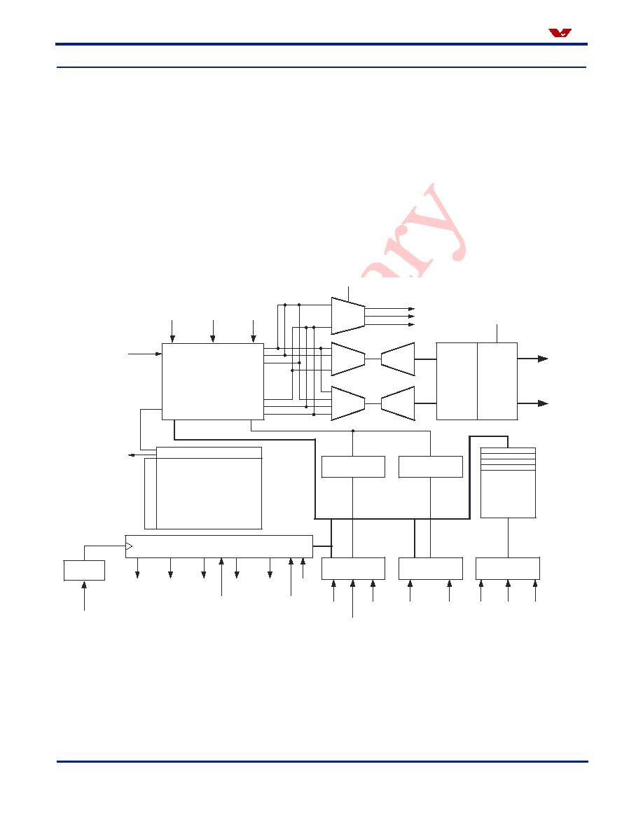
Figure 2
shows the functional block diagram of the OV7635/OV7135 image sensor. The OV7635/OV7135 includes:
∑
Image Sensor Array
(664 x 492 resolution)
∑
Analog Signal Processor
∑
Dual 10-Bit Analog-to-Digital Converters
∑
Exposure Control
∑
White Balance Control
∑
Video Timing Generator
∑
SCCB Interface
∑
Video Output Ports
≠
Digital Video Port
≠
Zoom Video Port (ZV)
Figure 2 Functional Block Diagram
DENB
PCLK
VSYNC
FODD CHSYNC
HREF
Image Array
(664 x 492)
B
R
G
MUX
ADC
ADC
Digital
Data
Formatter
Video
Port
Y[7:0]
Cr
Y
Cb
MUX
Analog Signal
Processor
Exposure
Detect
White Balance
Detect
Exposure
Control
White Balance
Control
SCCB
Interface
Column Sense Amp
Ro
w
S
e
l
e
c
t
Video Timing Generator
SBB
SIO_0
SIO_1
Control
Registers
.
.
.
.
UV[7:0]
MIR
FZEX
PROG
1/2
XVCLK1
SYS-CLK
FSIN
FREZ
AGCEN
AWBTH/
AWBTM
AWB
BUO
RVO
GYO
MUX
GAMMA
VcCNT
VcSAT
RGB
VrEQ
VcSHP

Functional Description
Version 1.2, April 21, 2003
Proprietary to OmniVision Technologies
3
O
mni
ision
Image Sensor Array
The OV7635/OV7135 sensor is a 0.25" CMOS imaging
device. The sensor contains approximately 326,688 pixels
(664 x 492).
Figure 3
shows the active regions of the
sensor array.
Figure 3 Sensor Array Region
The color filters are Bayer pattern. The primary color
BG/GR array is arranged in line-alternating fashion. Of the
326,688 pixels 307,200 are active. The other pixels are
used for black level calibration and interpolation.
The sensor array design is based on a field integration
read-out system with line-by-line transfer and an
electronic shutter with a synchronous pixel read-out
scheme.
When the column sample/hold circuit has sampled two
rows of pixels, the pixel data will shift out one-by-one into
an analog amplifier. The amplifier gain can either be
programmed by the user or controlled by the internal
automatic gain control circuit (AGC). The gain adjustment
range is 0-24 dB.
Analog Signal Processor
The amplified signals are then routed to the analog
processing section where the majority of signal
processing occurs. Specifically, in the channel balance
block, Red/Blue channel gain is increased or decreased to
match Green channel luminance level. The adjustment
range is 54 dB. This function can be done manually by the
user or with the internal automatic white balance controller
(AWB).
R
G
R
G
R
G
R
G
R
G
R
G
G
B
G
B
G
B
G
B
G
B
G
B
R
G
R
G
R
G
R
G
R
G
R
G
G
B
G
B
G
B
G
B
G
B
G
B
R
G
R
G
R
G
R
G
R
G
R
G
G
B
G
B
G
B
G
B
G
B
G
B
R
G
R
G
R
G
R
G
R
G
R
G
G
B
G
B
G
B
G
B
G
B
G
B
R
G
R
G
R
G
R
G
R
G
R
G
G
B
G
B
G
B
G
B
G
B
G
B
R
G
R
G
R
G
R
G
R
G
R
G
G
B
G
B
G
B
G
B
G
B
G
B
R
G
R
G
R
G
R
G
R
G
R
G
G
B
G
B
G
B
G
B
G
B
G
B
0
1
2
3
4
5
6
7
8
9
10
11
491
490
489
0
1
2
3
4
5
658
659
660
661
662
663
Column
Dummy
Dummy
Dummy
Dummy
Dummy
Dummy
Optical
Black
Dummy
Dummy
Dummy
Dummy
488
480
Active
Lines
R
o
w
The analog processing block also contains the circuitry
that performs color separation, color correction, automatic
gain control (AGC), gamma correction, black level
calibration, "knee" smoothing, aperture correction,
controls for picture luminance and chrominance, and hue
control for color. The analog video signals are based on
the following formula:
Y = 0.59G + 0.31R + 0.11B
U = B - Y
V = R - Y
where R, G, B are the equivalent color components in
each pixel.
YCbCr format is also supported, based on the formula
below:
Y = 0.59G + 0.31R + 0.11B
Cr = 0.713 (R - Y)
Cb = 0.564 (B - Y)
Dual 10-Bit Analog-to-Digital Converters
The YCbCr/RGB data signal from the analog processing
section is fed to two on-chip 10-bit analog-to-digital (A/D)
converters: one for the Y/G channel and one shared by
the CbCr/BR channels. The converted data stream is
further conditioned in the digital formatter. The processed
signal is delivered to the digital video port through the
video multiplexer which routes the user-selected 8-, or
4-bit video data to the correct output pins.
The on-chip 10-bit A/D operates at up to 12 MHz, and is
fully synchronous to the pixel rate. Actual conversion rate
is related to the frame rate. A/D black-level calibration
circuitry ensures:
∑
Black level of Y/RGB is normalized to a value of 16
∑
Peak white level is limited to 240
∑
CbCr black level is 128
∑
CbCr Peak/bottom is 240/16
∑
RGB raw data output range is 16/240
Note: Values 0 and 255 are reserved for sync flag.
Exposure Control
The algorithm used for the electronic exposure control is
based on the brightness of the full image. The exposure is
optimized for a "normal" scene that assumes the subject
is well lit relative to the background. In situations where
the image is not well lit, the automatic exposure control
(AEC) white/black ratio may be adjusted to suit the needs
of the application.
4
Proprietary to OmniVision Technologies
Version 1.2, April 21, 2003
OV7635/OV7135
CMOS VGA (640 x 480l) C
AMERA
C
HIP
TM
O
mni
ision
Additional C
AMERA
C
HIP
functions include:
∑
AGC that provides a gain boost of up to 24 dB
∑
White balance control that enables setting of proper
color temperature and can be programmed for
automatic or manual operation
∑
Separate saturation, brightness, hue, and sharpness
adjustments allow for further fine-tuning of the picture
quality and characteristics
White Balance Control
The OV7635/OV7135 C
AMERA
C
HIP
also provides control
over the White Balance ratio for increasing/decreasing the
image field Red/Blue component ratio. The sensor
provides a default setting sufficient for most applications.
Windowing
The windowing feature of the OV7635/OV7135
C
AMERA
C
HIPS
allows user-definable window sizing as
required by the application. Window size setting (in pixels)
ranges from 4 x 2 to 640 x 480, and can be positioned
anywhere inside the 664 x 492 boundary. Note that
modifying window size and/or position does not change
frame or data rate. The OV7635 C
AMERA
C
HIP
alters the
assertion of the HREF signal to be consistent with the
programmed horizontal and vertical region. The default
output window is 640 x 480. See
Figure 4
for details
Figure 4 Windowing
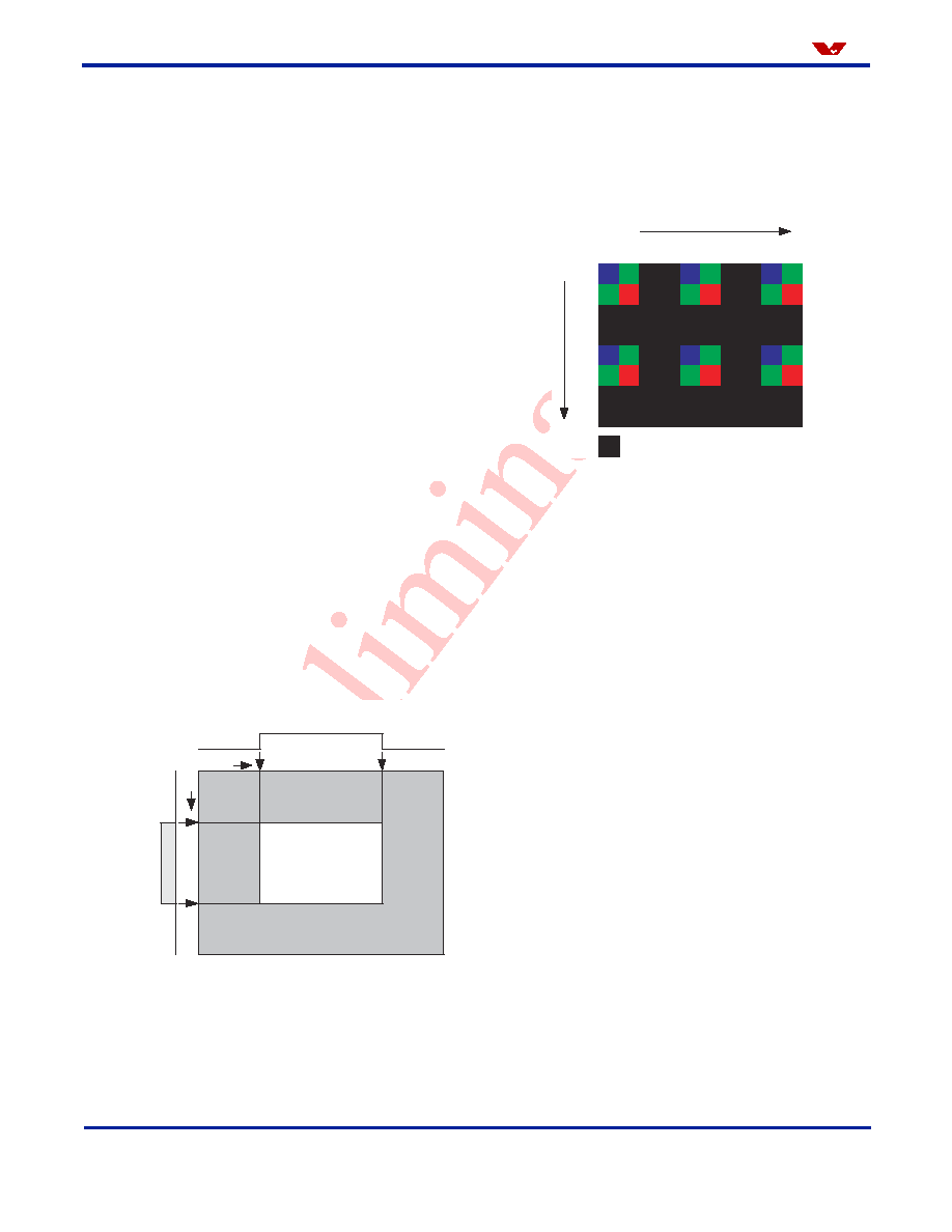
Sub-sampling Mode
The OV7635/OV7135 can be programmed to output in
320 x 240 (QVGA) images. This mode is available for
applications where higher resolution image capture is not
required. Default resolution is 640 x 480 pixels. The entire
Column
End
Sensor Array
Boundary
HREF
HR
E
F
Column
Display
Window
Column
Start
Row Start
Row End
R
o
w
array is sub-sampled for maximal image quality. Only half
of the pixel rate is required when programmed in this
mode. Both horizontal and vertical pixels are sub-sampled
to an aspect ratio of 4:2 as illustrated in
Figure 5
.
Figure 5 Sub-Sampling Mode
Video Timing Generator
In general, the timing generator controls the following
functions:
∑
Frame Rate Adjust
∑
Frame Division
∑
Frame Rate Timing
Frame Rate Adjust
OV7635/OV7135 offers two methods of frame rate
adjustment.
1.
Clock prescaler (see
"CLKRC" on page 22
)
By changing the system clock divide ratio, the frame
rate and pixel rate will change together. This
method can be used for dividing the frame/pixel rate
by: 1/2, 1/3, 1/4 ... 1/64 of the input clock rate.
2.
Line adjustment (see
"FRARH" on page 31
and see
"FRARL" on page 31
)
By adding dummy pixel timing in each line, the
frame rate can be changed while leaving the pixel
rate as is.
Frame Division
The OV7635/OV7135 frame rate divider can divide live
video output into a programmed number of time slots in
units of frames. The frame divider does not alter the video
data rate.
Figure 6
illustrates the operation of the frame
rate divider. Refer to register FSD (see
"FSD" on page 25
)
for details on setting the divider.
n
n+1
n+2
n+3
n+4
n+5
n+6
n+7
i
i+1
i+
2
i+3
i+4
i+
5
i+
6
i+7
i+8
i+9
Column
Row
Skipped Pixels
B
B
B
B
B
B
G
G
G
G
G
G
R
R
R
R
R
R
G
G
G
G
G
G

Functional Description
Version 1.2, April 21, 2003
Proprietary to OmniVision Technologies
5
O
mni
ision
Figure 6 Frame Division Example
Frame Rate Timing
Default frame timing is illustrated in
Figure 13
and
Figure 14
. Refer to
Table 1
for the actual pixel rate at
different frame rates.
Slave Operation Mode
The OV7635/OV7135 can be programmed to operate in
slave mode (default is master mode).
When used as a slave device, the OV7635/OV7135
changes the HSYNC and VSYNC outputs to input pins for
use as horizontal and vertical synchronization input
triggers supplied by the master device. The master device
must provide the following signals:
1.
System clock MCLK to XCLK1 pin
2.
Horizontal sync MHSYNC to CHSYNC pin
3.
Vertical frame sync MVSYNC to VSYNC pin
See
Figure 7
for slave mode connections and
Figure 8
for
detailed timing considerations.
Figure 7 Slave Mode Connection
Table 1
Frame and Pixel Rates
Frame Rage (fps)
15
10
7.5
6
5
PCLK (MHz)
24
16
12
9.6
8
NOTE: Based on 24 MHz external clock and internal PLL
on, frame rate is adjusted by the main clock divide method.
VSYNC
HREF
1 Frame
When: FD<7> = 1 FD<6> = 0 FD<5:0> = 000011
HREF
When: FD<7> = 1 FD<6> = 1 FD<5:0> = 000011
Y[7:0]
CHSYNC
VSYNC
XCLK1
MHSYNC
MVSYNC
MCLK
Master
Device
OV7635
(OV7135)
Figure 8 Slave Mode Timing
Luminance Average Calculator
The OV7635/OV7135 provides frame-averaged
luminance level. Access to the data is via the serial control
port. Average values are calculated from 128 pixels per
line (64 in VGA).
Reset
The OV7635/OV7135 includes a RESET pin (pin 13 - see
"RESET" on page 11
) that forces a complete hardware
reset when it is pulled high (VCC). The OV7635/OV7135
clears all registers and resets them to their default values
when a hardware reset occurs. Reset can also be initiated
through the SCCB interface.
Power-Down Mode
Two methods are available to place the OV7635/OV7135
into power-down mode: hardware power-down and SCCB
software power-down.
To initiate hardware power-down, the PWDN pin (pin 4 -
see
"PWDN" on page 11
) must be tied to high (+3.3 VDC).
When this occurs, the OV7635 internal device clock is
halted and all internal counters are reset. The current
draw is less than 10 µA in this standby mode.
Executing a software power-down through the SCCB
interface suspends internal circuit activity, but does not
halt the device clock. The current requirements drop to
less than 1mA in this mode.
SCCB Interface
The OV7635/OV7135 provides an on-chip SCCB serial
control port that allows access to all internal registers, for
complete control and monitoring of the OV7635/OV7135
operation.
NOTE:
1) T
HS
> 6 T
clk
, Tvs > T
line
2) T
line
= 1520 x T
clk
(SXGA); T
line
= 800 x T
clk
(VGA)
3) T
frame
= 1050 x T
line
(SXGA); T
frame
= 500 x T
line
(VGA)
T
frame
T
VS
T
line
T
clk
T
HS
VSYNC
HSYNC
MCLK