Äîêóìåíòàöèÿ è îïèñàíèÿ www.docs.chipfind.ru
Design, Specifications are subject to change without notice. Ask factory for technical specifications before purchase and/or use.
Whenever a doubt about safety arises from this product, please inform us immediately for technical consultation without fail.
Ð EF72 Ð
Ultrasonic Ceramic Sensors
(Ultrasonic Ceramic Transducers)
Type:
U/H/S/Q
Ultrasonic Ceramic Sensor consisting of a disc type/a
bimorph type piezoelectric ceramic vibrator is a sensor
for transmitting and receiving ultrasonic wave in the air.
s
Features
q
High output S.P.L.: 112 dB min. (Ex. EFRTUB40K5)
q
High sensitivity: Ð45 dB min. (Ex. EFRRUB40K5)
q
Excellent temperature and humidity durability
q
Small in size
q
Applicable to multi-function remote control system
because of its wide bandwidth
Ultrasonic Ceramic Sensors
s
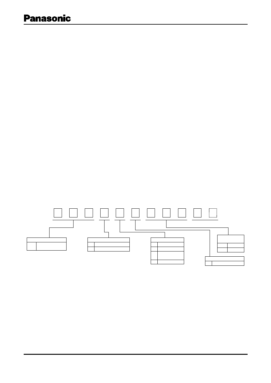
Explanation of Part Numbers
E
1
F
2
R
3
4
5
6
7
8
9
10
11
Design No.
E
F
Type
U
H
S
Q
Standard Type
Compact Type
Temperature
Stable Type
Enclosed Type
Product Code
Ultrasonic
Ceramic Sensors
EFR
Nominal
Frequency
Applications
R
T
For reception use
For transmission use
Construction of Element
B
Bimorph Type
25K
40K
25 kHz
40 kHz
s
Recommended Applications
Ultrasonic wave transmitter and receiver for;
q
Proximity switch for burglar alarm system, parking
meter and automatic door opener
q
Remote control equipment for such as air conditioner
and garage door opener
Design, Specifications are subject to change without notice. Ask factory for technical specifications before purchase and/or use.
Whenever a doubt about safety arises from this product, please inform us immediately for technical consultation without fail.
Ð EF73 Ð
s
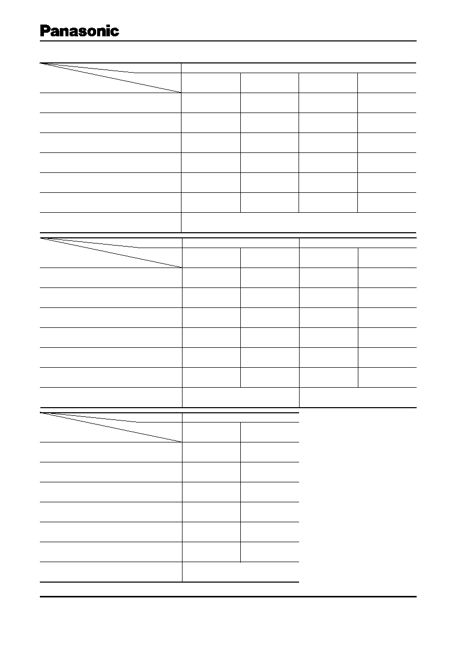
Ratings and Characteristics
Ultrasonic Ceramic Sensors
Type
Standard Type
Part No.
EFRRUB40K5
EFRTUB40K5
EFRRUB25K5
EFRTUB25K5
Item
Nominal Frequency
(kHz)
40.0
40.0
25.0
25.0
Sensitivity
(dB)
V
Ð45 min.
Ñ
Ð45 min.
Ñ
Sound Pressure Level
(dB)
VV
Ñ
112 min.
Ñ
105 min.
Bandwidth
(kHz)
4.0 min.
4.0 min.
2.5 min.
2.5 min.
Application
Receiver
Transmitter
Receiver
Transmitter
Maximum Input Voltage
(Vrms)
Ñ
20
Ñ
20
Operating Temperature Range
(ûC)
Ð20 to 60
Type
Compact Type
Temperature Stable Type
Part No.
EFRRHB40K5
EFRTHB40K5
EFRRSB40K5
EFRTSB40K5
Item
Nominal Frequency
(kHz)
40.0
40.0
40.0
40.0
Sensitivity
(dB)
V
Ð47 min.
Ñ
Ð50 min.
Ñ
Sound Pressure Level
(dB)
VV
Ñ
110 min.
Ñ
105 min.
Bandwidth
(kHz)
4.0 min.
4.0 min.
4.0 min.
4.0 min.
Application
Receiver
Transmitter
Receiver
Transmitter
Maximum Input Voltage
(Vrms)
Ñ
20
Ñ
20
Operating Temperature Range
(ûC)
Ð20 to 60
Ð40 to 100
Type
Enclosed Type
Part No.
EFRRQB40K5
EFRTQB40K5
Item
Nominal Frequency
(kHz)
40.0
40.0
Sensitivity
(dB)
V
Ð55 min.
Ñ
Sound Pressure Level
(dB)
VV
Ñ
105 min.
Bandwidth
(kHz)
1.0 min.
1.0 min.
Application
Receiver
Transmitter
Maximum Input Voltage
(Vrms)
Ñ
20
Operating Temperature Range
(ûC)
Ð20 to 60
V
0 dB=1 V/Pa
VV
0 dB=2
×
10
Ð5
Pa
Design, Specifications are subject to change without notice. Ask factory for technical specifications before purchase and/or use.
Whenever a doubt about safety arises from this product, please inform us immediately for technical consultation without fail.
Ð EF74 Ð
s
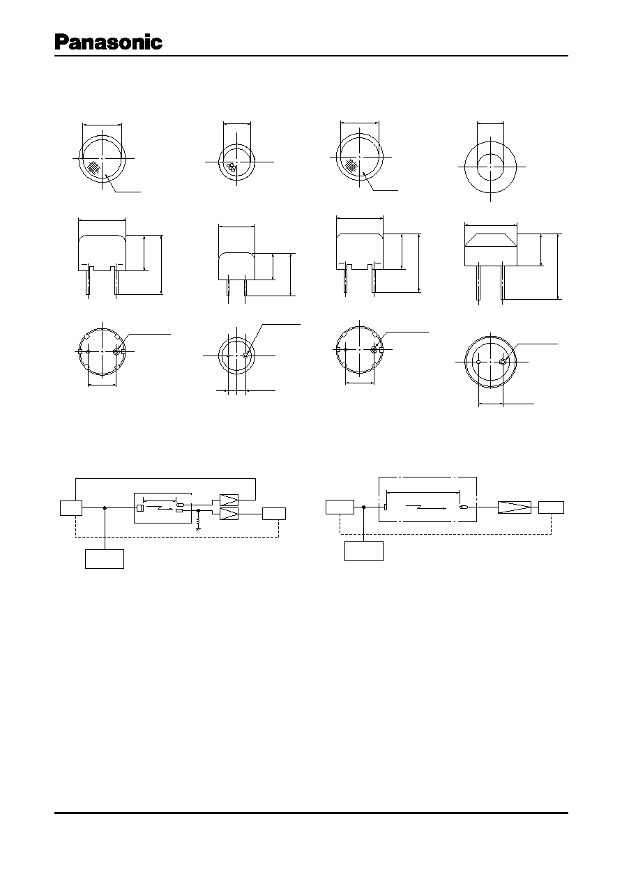
Dimensions in mm (not to scale)
s
Test Circuits Diagram
RL
: 3.9 k
UCS : Ultrasonic Ceramic Sensor
SCM : Standard Condenser Microphone Brel & Kj¾r 4135
Amp. : Amplifier
Brel & Kj¾r 2606
Osc. : Oscillator
Brel & Kj¾r 1013
Rec. : Recorder
Brel & Kj¾r 2305
Tw. : Tweeter
UCS : Ultrasonic Ceramic Sensor
SCM : Standard Condenser Microphone Brel & Kj¾r 4135
Amp. : Amplifier
Brel & Kj¾r 2606
Osc. : Oscilator
Brel & Kj¾r 1013
Rec. : Recorder
Brel & Kj¾r 2305
Ein
: 10 Vrms.
Ultrasonic Ceramic Sensors
10.0
±
0.5
2-f 1.2
±
0.1
f 16.0
±
0.5
21.0
±
1.0
12.0
±
0.5
f 13.0
±
0.5
Screen
7.5
±
0.5
2-f 0.8
±
0.2
f 18.0
±
0.5
24.5
±
1.0
12.0
±
0.5
f 10.0
±
1.5
8.0
±
0.5
f 12.6
±
0.5
9.5
±
0.5
15.6
±
1.0
f 10.0
±
0.5
2-f 0.8
±
0.1
10.0
±
0.5
2-f 1.2
±
0.1
f 16.0
±
0.5
21.0
±
1.0
12.0
±
0.5
f 13.0
±
0.5
Screen
feed back
Osc.
Silent Box
Amp.
RL
Amp.
Rec.
30 cm
SCM
UCS
Tw.
Freq.
Counter
Test Circuit Diagram for Receiver
Silent Box
Amp.
30cm
SCM
UCS
Freq.
Counter
Test Circuit Diagram for Transmitter
Rec.
Osc.
Ein
[Sound Pressure Level]
Maximum sound pressure level from the specimen shall
be measured in accordance with the specified Test Circuit
and the specified test conditions. The output sound
pressure shall be expressed in decibeles (dB), where
2
×
10
Ð5
Pa is 0 dB.
Type U
Type H
Type S
Type Q
Standard Type
Compact Type
TemperatureStable Type
Enclosed Type
[Sensitivity]
Output voltage of the specimen shall be measured in
accordance with the specified Test Circuit and the
specified test conditions. The output voltage shall be
expressed in decibeles (dB), where 1 V/Pa is 0 dB.
Design, Specifications are subject to change without notice. Ask factory for technical specifications before purchase and/or use.
Whenever a doubt about safety arises from this product, please inform us immediately for technical consultation without fail.
Ð EF75 Ð
s
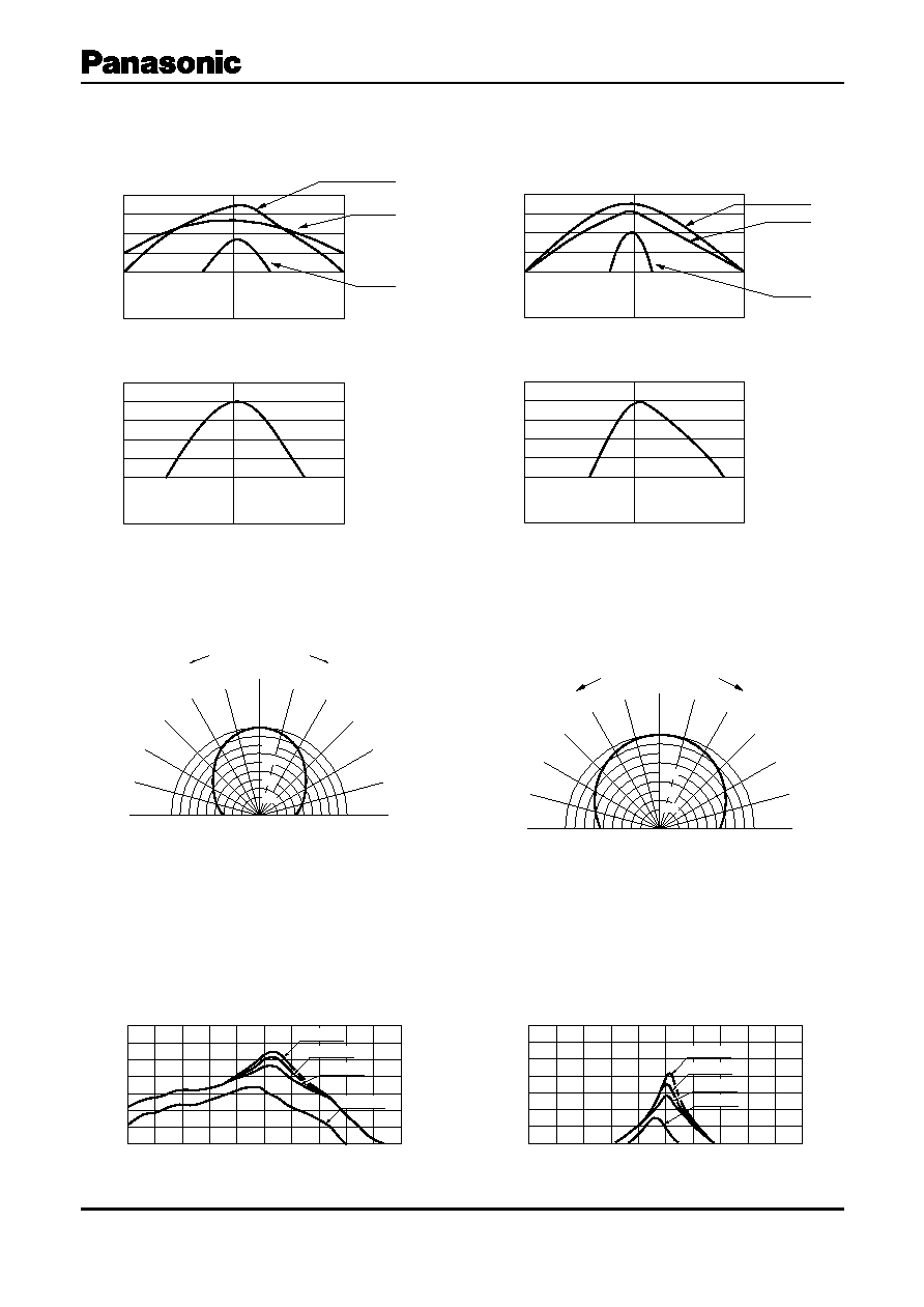
Typical Characteristics
Frequency Characteristics (Sensitivity)
Frequency Characteristics (Sound Pressure Level)
35
40
45
Frequency (kHz)
Ð40
Ð45
Ð50
Ð55
Sensitivity (dB)
Ð35
Ð40
Ð45
Ð50
Ð55
20
25
30
Frequency (kHz)
Sensitivity (dB)
Type U / H
TypeS
TypeQ
Type Q
0
90¡
15¡
30¡
45¡
60¡
75¡
15¡
30¡
45¡
60¡
75¡
90¡
0
Ð10
Ð50
Ð30
Ð10
0
Ð30
Ð10 0
Attenuation (dB)
Le
ft
Righ
t
Ð20
Ð30
Ð40
Directivity
Ultrasonic Ceramic Sensors
0û
15û
30û
45û
60û
75û
90û
15û
30û
45û
60û
75û
90û
Ð50
Ð30
Ð10 0
Ð30
Ð10
0
Attenuation (dB)
-10
-30
-40
-20
0
Type U/H/S
0 dB= Ð41 dB
Left
Right
35
40
45
Frequency (kHz)
115
110
105
100
Output S.P.L. (dB)
115
110
105
100
95
20
25
30
Frequency (kHz)
Output S.P.L.(dB)
Type U / H
TypeS
TypeQ
EFRTUB25K
EFRRUB25K
Frequency (kHz)
Sensitivity (dB)
35
40
45
Ð30
Ð35
Ð40
Ð45
Ð50
Ð55
100 k
10 k
3.9 k
1 k
Characteristic Change vs. Load Resistance
Type U/H/S
(40 kHz)
Type Q
Frequency (kHz)
Sensitivity (dB)
35
40
45
Ð30
Ð35
Ð40
Ð45
Ð50
Ð55
100 k
10 k
3.9 k
1 k

Design, Specifications are subject to change without notice. Ask factory for technical specifications before purchase and/or use.
Whenever a doubt about safety arises from this product, please inform us immediately for technical consultation without fail.
Ð EF76 Ð
Ultrasonic Ceramic Sensors
Application Notes
Because the Ultrasonic Sensors are designed for
use in the air, they can not be used under the
water or others liquid.
1. Design Engineering Notes
1. Application of DC voltage
DC voltage shall not be applied to the
Ultrasonic Sensors because insulation
resistance may deteriorate.
2. Maximum Input Voltage
The Ultrasonic Sensors shall not be operated
beyond the specified ÒMaximum Input VoltageÓ
in the catalog or the specifications.
3. Characteristics change owing to load
impedance
Center frequency and sensitivity change in
accordance with load impedance.
Therefore, the load characteristics chart shall
be taken into consideration in designing
circuit.
4. In the Design of Transmitting Circuits
It shall be noted that the impedance of the
device is as low as 500
(approximately) at
the resonance frequency.
2. Mounting Notes
1. Installation
It is recommended to hold the Ultrasonic
Sensors by means of rubber
V
sheets or cushions
for absorption of mechanical stresses such as
shock and vibration.
V
Except sulfurated rubber
2. Soldering
Soldering of the lead terminals shall be done
at a position of 2.5 mm or more apart from
bottom plain of the devices.
3. Bending force to the Terminals
Abnormal bending force shall not be applied
to the terminals of the Sensors, otherwise
holding parts of the terminals may be easily
broken, resulting in failures and damages of
the devices.
4. Directivity
Please be cafeful enough in deciding facing
position of the sensor because of directivity.
3. Storage Notes
1. Environmental Conditions
The Ultrasonic Sensors shall not be operated
and/or stored under following environmental
conditions;
a) To be exposed directly to water or salt
water.
b) Under conditions of dew formation or frost.
c) Under conditions of corrosive atomosphere
such as hydrogen sulfide, sulfurous acid,
chlorine and ammonia.
2. Long Term Storage
The Ultrasonic Sensors shall not be stored
under severe conditions of high temperature
and high humidity. Store them indoors under
40 ¡C max. and 75 %RH max. Use them within
one year and check the solderbility before
use.