s
Overview
The AN5138NK is an integrated circuit designed for
video-IF and audio-IF processing circuits, in color TV and
VCR.
s
Features
·
By adopting built-in VCO PLL-type video-detector cir-
cuit, the high preformance IC-detector system can be
realized for sound multiplex and tele-text broadcasting.
·
Quadrature sound FM detector built-in.
·
Frequency characteristics compensation pin (Pin20)
VCR-switch pin (Pin5)
·
Sound-output level-adjustment pin (Pin25)
1
ICs for TV
AN5138NK
Video IF Amplifier, PLL Detector, AGC, AFC, SIF IC for Color TV
1
2
3
4
5
6
7
8
9
10
11
12
13
14
19
18
17
16
15
20
21
22
23
24
25
26
27
28
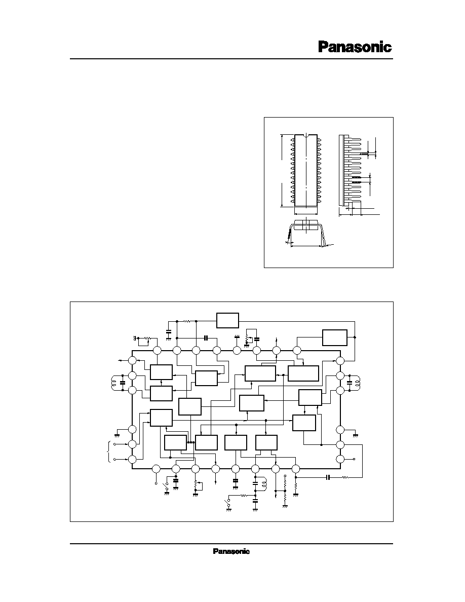
26.7
±
0.3
8.4
±
0.3
10.16
±
0.25
3 to 15°
0.3
+ 0.1
0.05
4.8
±
0.25
1.05
±
0.25
3.05
±
0.25
1.778
0.5
±
0.1
0.9
±
0.25
Unit : mm
28-Pin Shrunk DIL Plastic Package
25
24
23
22
21
20
19
18
17
16
15
14
13
12
11
10
9
8
7
6
5
4
2
3
1
28
27
26
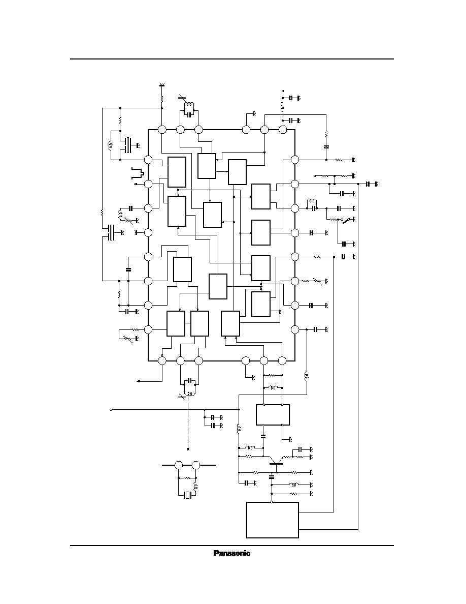
+
+
Audio Level Adj.
SIF
Filter
Level
Adj.
VIF
Amp.
FM
Det.
SIF
Amp.
VTR
SW
Video
Det.
Noise
Inverter
Video
Inverter
VCO
APC
Det.
SIF
Trap
Video Output
AFC
Lock
Det.
IF
AGC
RF
AGC
Audio
Output
IF
Input
VTR SW
AFC
SW
AFC
Out.
V
CC
V
CC
V
CC
IF
AGC
Filter
RF
AGC
Out.
RF
AGC
Delay
Adj.
s
Block Diagram
2
ICs for TV
AN5138NK
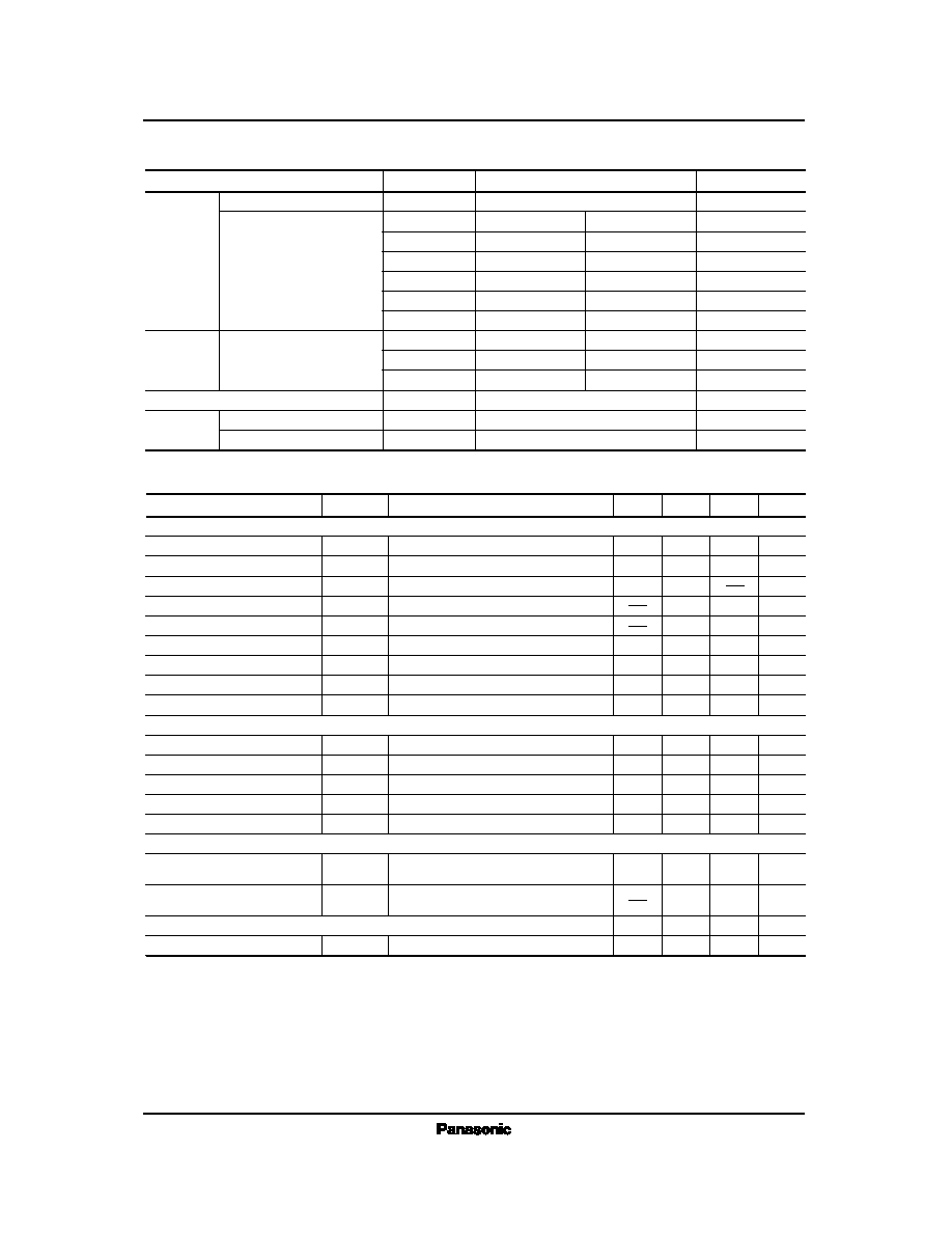
Parameter
Symbol
Rating
Unit
V
CC
V
5-1, 14, 21
V
6-1, 14, 21
V
7-1, 14, 21
V
10-1, 14, 21
I
17
I
19
P
D
T
opr
T
stg
Circuit Voltage
Circuit Current
Supply Voltage
Operating Ambient Temperature
Power Dissipation (Ta=70°C)
Storage Temperature
Voltage
Current
Temperature
13.8
1,300
20 to + 70
55 to + 150
V
mW
°C
°C
V
mA
V
V
V
mA
V
4, 12-1, 14, 21
0
V
4, 12-1, 14, 21
0
V
4, 12-1, 14, 21
0
V
4, 12-1, 14, 21
0
7
+ 0.5
7
+ 0.5
V
18-1, 14, 21
V
25-1, 14, 21
I
26
V
V
4, 12-1, 14, 21
0
V
8.0
0
mA
5
+ 0.5
s
Absolute Maximum Ratings
(Ta=25°C)
f= 58.75MHz, V
i
= 80dB
µ
, m= 87.5%
1.9
2.2
2.5
V
P-P
50
70
90
mA
V
O
I
4
+ I
12
S
(IN)
V
1 (max.)
DG
G
RFAGC
V
O
= 3dB
Video detector output
Input sensitivity
Max. allowable input
49
103
5.5
40
53
108
2
6.5
44
57
6
7.5
48
dB
µ
dB
µ
%
MHz
dB
Parameter
min
Condition
typ
max
Unit
Symbol
IF Amplifier · Detection · AGC · AFC Circuit
Differential gain
Differential phase
Frequency characteristics
RF AGC gain
AFC phase det. sensitivity
AFC center voltage
VCO · APC Circuit
VCO control sensitivity
APC pull-in range (1)
APC pull-in range (2)
SIF Circuit
Circuit current
DP
fc
µ
V
10
f
APC (1)
f
APC (2)
f =58.75MHz, V
i
= 80dB
µ
, m= 87.5%
f =58.75MHz, V
i
= 80dB
µ
, m= 87.5%
f =10kHz, V
i
=10mV
R
L
= 68k
//82k
R
L
= 68k
//82k
V
13
= 2V
2
5
deg
30
45
60
mV/kHz
4.2
6.5
8.2
V
0.8
1.5
2.5
MHz
3
4.5
6
kHz/mV
+ 0.85
+1.5
+ 2.5
MHz
3.5
2.5
1.6
MHz
VCO max. variable range (1)
VCO max. variable range (2)
Total detector output
Input limiting voltage
DC Characteristics
f
V (1)
f
V (2)
V
O
V
i (lim)
V
O
= 3dB
V
13
= 3V
f
o
= 4.5MHz, f
m
= 400Hz
f=
±
25kHz, V
i
=100dB
µ
f
o
= 4.5MHz, f
m
= 400Hz
f=
±
25kHz, V
i
=100dB
µ
3.4
2.4
1.4
MHz
490
620
950
mV
rms
42
47
dB
µ
s
Electrical Characteristics
(V
CC
=12V, Ta=25°C)