1
Band Switching Diodes
MA2Z077
Silicon epitaxial planar type
For band switching
I Features
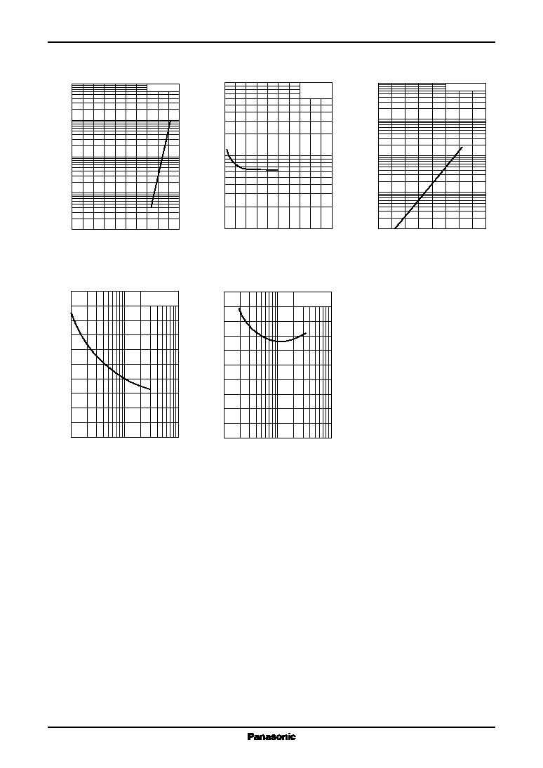
∑ Low forward dynamic resistance r
f
∑ Less voltage dependence of diode capacitance C
D
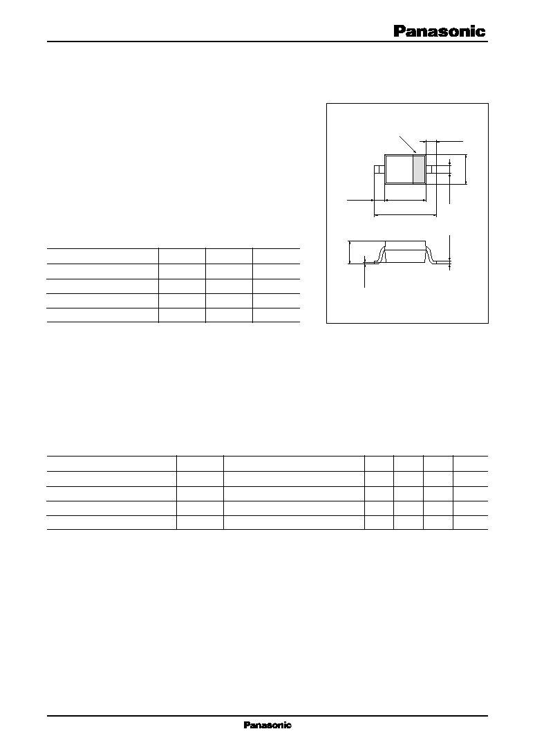
∑ S-mini type package, allowing downsizing of equipment and
automatic insertion through the taping package
I Absolute Maximum Ratings T
a
= 25
∞C
Unit : mm
Parameter
Symbol
Rating
Unit
Reverse voltage (DC)
V
R
35
V
Forward current (DC)
I
F
100
mA
Operating ambient temperature
*
T
opr
-25 to +85
∞C
Storage temperature
T
stg
-55 to +150
∞C
Parameter
Symbol
Conditions
Min
Typ
Max
Unit
Reverse current (DC)
I
R
V
R
= 33 V
0.01
100
nA
Forward voltage (DC)
V
F
I
F
= 100 mA
0.92
1
V
Diode capacitance
C
D
V
R
= 6 V, f = 1 MHz
0.9
1.2
pF
Forward dynamic resistance
*
r
f
I
F
= 2 mA, f = 100 MHz
0.65
0.85
I Electrical Characteristics T
a
= 25
∞C
Note) 1
Rated input/output frequency: 100 MHz
2
* : r
f
measuring instrument: YHP MODEL 4191A RF IMPEDANCE ANALYZER
Marking Symbol: 4B
Note) * : Maximum ambient temperature during operation
1 : Anode
2 :Cathode
S-Mini Type Package (2-pin)
2.5
± 0.2
1.7
± 0.1
1.25
±
0.1
0.9
±
0.1
0 to 0.05
0.4
± 0.15
0.3
+
0.1
-
0.05
0.16
+
0.1
-
0.06
1
2
0.4
± 0.15
INDICATES
CATHODE