1
GaAs Hall Devices
OH10004
GaAs Hall Device
Magnetic sensor
I Features
∑ Hall voltage: typ. 150 mV (V
C
= 6 V, B = 0.1 T)
∑ Input resistance: typ. 0.85 k
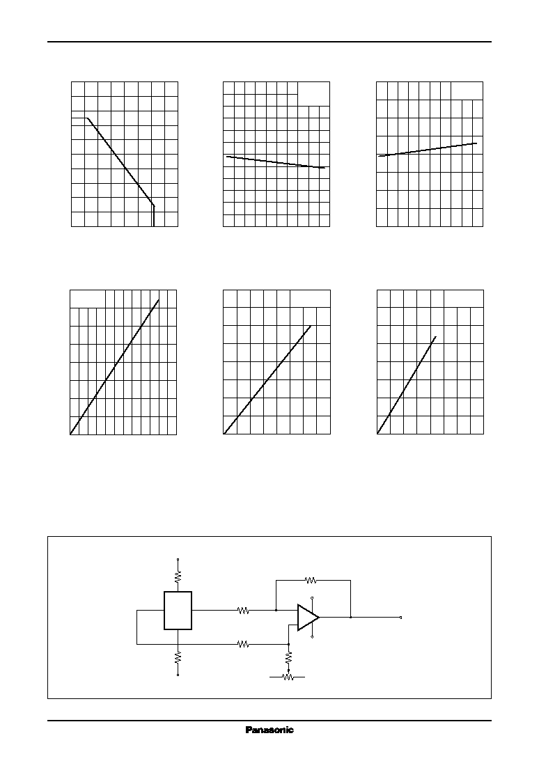
∑ Satisfactory linearity of GaAs hall voltage with respect to the
magnetic field
∑ Small temperature coefficient of the hall voltage: - 0.06%/∞C
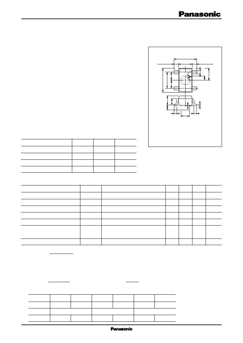
∑ Mini type (4-pin) package with positioning projection. Allowing
automatic insertion through the magazine package.
I Applications
∑ Various hall motor (VCR, phonograph, VD, CD, and FDD)
∑ Automotive equipment
∑ Industrial equipment
I Absolute Maximum Ratings T
a
= 25∞C
Unit : mm
1 : V
H
Output
(-) side
2 : V
C
Input
(-) side
3 : V
H
Output
(+) side
4 : V
C
Input
(+) side
Mini Type Package (4-pin) with positioning projection
Parameter
Symbol
Rating
Unit
Control voltage
V
C
12
V
Power dissipation
P
D
150
mW
Operating ambient temperature
T
opr
-30 to +125
∞C
Storage temperature
T
stg
-55 to +125
∞C
Parameter
Symbol
Conditions
Min
Typ
Max
Unit
Hall voltage
*1, 4
V
H
V
C
= 6 V, B = 0.1 T
130
150
170
mV
Unequilibrium ratio
*2, 4
V
HO
/V
H
V
C
= 6 V, B = 0 T/B = 0.1 T
±12
%
Input resistance
R
IN
I
C
= 1 mA, B = 0 T
0.50
0.85
k
Output resistance
R
OUT
I
C
= 1 mA, B = 0 T
5
k
Temperature coefficient of hall voltage
I
C
= 6 mA, B = 0.1 T
-0.06
%/
∞C
Temperature coefficient of input
I
C
= 1 mA, B = 0 T
0.3
%/
∞C
resistance
Linearity of hall voltage
*3
I
C
= 6 mA, B = 0.1 T/0.5 T
2
%
I Electrical Characteristics T
a
= 25∞C
1.5
± 0.2
1.0 ± 0.025
0.5
±
0.1
1.9
±
0.2
2.9
±
0.2
1.45
±
0.2
(0.5 R)
0.8
0.95
0.95
0.4
± 0.2
0.4
± 0.2
2
3
1
4
1.1
+
0.1
-
0.05
0.16
+
0.1
-
0.06
2.8
+ 0.2
- 0.3
0 to 0.1
0.4
+
0.1
-
0.05
0.5 R
0.65
± 0.15
0.65
± 0.15
Class
HQ
HR
IQ
IR
KQ
KR
V
H
(mV)
130 to 158
142 to 170
130 to 158
142 to 170
130 to 158
142 to 170
V
HO
/V
H
(%)
-5 to +5
+2 to +12
-2 to -12
Marking Symbol
4HQ
4HR
4IQ
4IR
4KQ
4KR
Marking Symbol: 4
Note) *1 : V
H
=
V
H
+
+V
H
-
2
*2 : Unequilibrium ratio is a percentage of V
HO
with respect to V
H
.
*3 : The linearity
of V
H
is a percentage of a difference between cumulative sensitivity of K
H1
and K
H5
which are measured
respectively at B = 0.1 T and 0.5 T to their average. That is,
=
K
H5
-K
H1
(the cumulative sensitivity K
H
=
V
H
)
1/2(K
H1
+K
H5
)
I
C
B
*4 : V
H
, V
HO
/V
H
rank classification