 | –≠–ª–µ–∫—Ç—Ä–æ–Ω–Ω—ã–π –∫–æ–º–ø–æ–Ω–µ–Ω—Ç: 84140-01 | –°–∫–∞—á–∞—Ç—å:  PDF PDF  ZIP ZIP |
PEREGRINE SEMICONDUCTOR CORP.
|
http://www.peregrine-semi.com
Copyright
Peregrine Semiconductor Corp. 2003
Page 1 of 5
Product Description
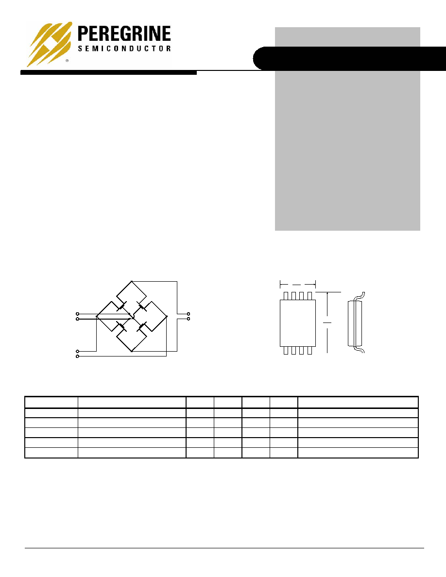
Figure 1. Functional Schematic Diagram
RF
LO
IF
Figure 2. Package Type
Table 1. AC and DC Electrical Specifications @ +25 ∞C
Symbol Characteristics
Min
Typ
Max
Units
Test
Conditions
F
TYP
Operating Frequency Range
1
DC
6.0
GHz
V
DS
Drain-Source
Voltage
330 mV
V
GS
= +3V, I
DS
= 40 mA
V
DS
Match
Drain-Source Voltage Match
20
mV
V
T
Threshold
Voltage
-100 mV
V
DS
= 0.1V; per ASTM F617-00
R
DS
Drain-Source `ON' Resistance
8.25
V
GS
= +3V, I
DS
= 40 mA
Note 1: Typical untested operating frequency range of Quad MOSFET transistors.
Advanced Information
PE84140
Ultra-High Linearity Broadband
Quad MOSFET Array
Features
∑ Ultimate Quad MOSFET array
∑ Ultra-high linearity, broadband
performance beyond 6.0 GHz
∑ Ideal for mixer applications
∑ Up/down conversion
∑ Low conversion loss
∑ High LO Isolation
∑ Optimized for stringent military
applications
The PE84140 is an ultra-high linearity, passive broadband
Quad MOSFET array with high dynamic range performance
capable of operation beyond 6.0 GHz. This quad array
operates with differential signals at all ports (RF, LO, IF),
allowing mixers to be built that use LO powers from -7 dBm
to +20 dBm. Typical applications range from frequency
up/down-conversion to phase detection for Cellular/PCS
Base Stations, Wireless Broadband Communications and
STB/Cable modems.
The PE84140 is optimized for stringent military applications.
Fabricated in Peregrine's patented UTSiÆ (Ultra Thin
Silicon) CMOS technology, the PE84140offers excellent RF
performance with the economy and integration of
conventional CMOS.
8-lead MSOP
5.05
4.75
3.05
2.85
PE84140
Product Specification
Copyright
Peregrine Semiconductor Corp. 2003
File No. 70/0127~00A
|
UTSi
CMOS RFIC SOLUTIONS
Page 2 of 5
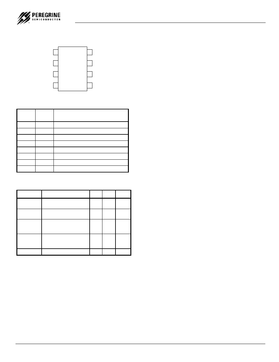
Figure 3. Pin Configuration
1
2
3
4
8
7
6
5
PE84140
LOM
LOP
GND
IFP
RFM
RFP
GND
IFM
Table 2. Pin Descriptions
Pin
No.
Pin
Name
Description
1
LOM
LO Input Connection (Gate)
2
LOP
LO Input Connection (Gate)
3 GND
Ground
Connection
4
IFP
IF Output Connection (Drain)
5
IFM
IF Output Connection (Drain)
6 GND
Ground
Connection
7
RFP
RF Input Connection (Source)
8
RFM
RF Input Connection (Source)
Table 3. Absolute Maximum Ratings
Symbol Parameter/Conditions Min Max Units
T
ST
Storage temperature
range
-65 150
∞C
T
OP
Operating temperature
range
-55 125
∞C
V
DC + AC
Maximum DC plus peak
AC voltage across Drain-
Source
±3.3 V
V
DC+AC
Maximum DC plus peak
AC voltage across Gate-
Drain or Gate-Source
±4.2 V
V
ESD
ESD Sensitive Device
250
V
Electrostatic Discharge (ESD) Precautions
This MOSFET device has minimally protected
inputs and is highly susceptible to ESD damage.
When handling this UTSi device, observe the same
precautions that you would use with other ESD-
sensitive devices.
Latch-Up Avoidance
Unlike conventional CMOS devices, UTSi CMOS
devices are immune to latch-up.
Device Description
The PE84140 passive broadband Quad MOSFET
array is designed for use in up-conversion and
down-conversion applications for high performance
systems.
The PE84140 is an ideal mixer core for a wide
range of mixer products, including module level
solutions that incorporate baluns or other single-
ended matching structures enabling three-port
operation.
The performance level of this passive mixer is
made possible by the very high linearity afforded by
Peregrine's UTSi CMOS process.
PE84140
Product Specification
PEREGRINE SEMICONDUCTOR CORP.
|
http://www.peregrine-semi.com
Copyright
Peregrine Semiconductor Corp. 2003
Page 3 of 5
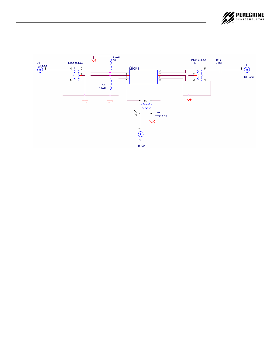
Figure 4. Typical Schematic
PE84140
Product Specification
Copyright
Peregrine Semiconductor Corp. 2003
File No. 70/0127~00A
|
UTSi
CMOS RFIC SOLUTIONS
Page 4 of 5
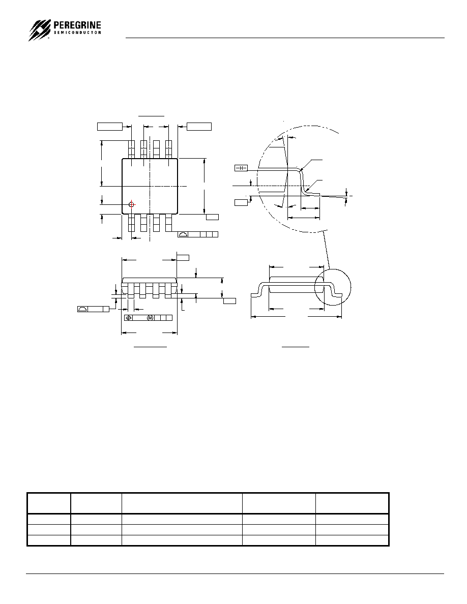
FRONT VIEW
2.95±0.10
0.08
A B C
0.33+0.07
-0.08
0.10 A
0.10±0.05
3.00±0.10
0.86±0.08
1.10 MAX
- C -
- A -
1
0.65BSC
0.51±0.13
2.45±0.10
0.51±0.13
2X
8
3.00±0.10
.25 A B C
2
3
4
- B -
.525BSC
TOP VIEW
5
6
7
4.90±0.15
3.00±0.10
SIDE VIEW
2.95±0.10
R 0.90 MIN
0.95 BSC
0.55±0.15
R 0.90 MIN
0
o
6
o
12
o
REF
12
o
REF
0.25
GAGE
PLANE
Figure 5. Package Drawing
8-lead MSOP
Table 4. Ordering Information
Order
Code
Part Marking
Description
Package
Shipping
Method
84140-01
84140
PE84140-08MSOP-50A
8-lead MSOP
50 units / Tube
84140-02
84140
PE84140-08MSOP-2000C
8-lead MSOP
2000 units / T&R
84140-00
PE84140-EK
PE84140-08MSOP-EK
Evaluation Kit
1 / Box

PE84140
Product Specification
PEREGRINE SEMICONDUCTOR CORP.
|
http://www.peregrine-semi.com
Copyright
Peregrine Semiconductor Corp. 2003
Page 5 of 5
Sales Offices
United States
Peregrine Semiconductor Corp.
6175 Nancy Ridge Drive
San Diego, CA 92121
Tel 1-858-455-0660
Fax 1-858-455-0770
Japan
Peregrine Semiconductor K.K.
5A-5, 5F Imperial Tower
1-1-1 Uchisaiwaicho, Chiyoda-ku
Tokyo 100-0011 Japan
Tel: 03-3507-5755
Fax: 03-3507-5601
Europe
Peregrine Semiconductor Europe
B‚timent Maine
13-15 rue des Quatre Vents
F- 92380 Garches, France
Tel 33-1-47-41-91-73
Fax 33-1-47-41-91-73
For a list of representatives in your area, please refer to our Web site at: http://www.peregrine-semi.com
Data Sheet Identification
Advance Information
The product is in a formative or design stage. The data sheet
contains design target specifications for product
development. Specifications and features may change in any
manner without notice.
Preliminary Specification
The data sheet contains preliminary data. Additional data
may be added at a later date. Peregrine reserves the right to
change specifications at any time without notice in order to
supply the best possible product.
Product Specification
The data sheet contains final data. In the event Peregrine
decides to change the specifications, Peregrine will notify
customers of the intended changes by issuing a PCN
(Product Change Notice).
The information in this data sheet is believed to be reliable. However,
Peregrine assumes no liability for the use of this information. Use
shall be entirely at the user's own risk.
No patent rights or licenses to any circuits described in this
data sheet are implied or granted to any third party.
Peregrine's products are not designed or intended for use in devices
or systems intended for surgical implant, or in other applications
intended to support or sustain life, or in any application in which the
failure of the Peregrine product could create a situation in which
personal injury or death might occur. Peregrine assumes no liability
for damages, including consequential or incidental damages, arising
out of the use of its products in such applications.
Peregrine products are protected under one or more of the following
U.S. patents: 6,090,648; 6,057,555; 5,973,382; 5,973,363; 5,930,638;
5,920,233; 5,895,957; 5,883,396; 5,864,162; 5,863,823; 5,861,336;
5,663,570; 5,610,790; 5,600,169; 5,596,205; 5,572,040; 5,492,857;
5,416,043. Other patents are pending.
Peregrine, the Peregrine logotype, Peregrine Semiconductor Corp., and UTSi
are registered trademarks of Peregrine Semiconductor Corporation.
Copyright © 2003 Peregrine Semiconductor Corp. All rights reserved.