Triggered
Vacuum Gaps
GPV-Series
T
he Triggered Vacuum
Spark Gaps are ideal high-voltage
switches for applications where a wide
operating voltage range is desired. The
low end of the operating voltage range
is independent of the Static Breakdown
Voltage (SBV). Operating ranges from
300 volts to 80 kilovolts are possible.
Switching times (from the trigger input
to the start of main gap current flow) of
less than 1 microsecond may be
achieved when using a suitable trigger.
These switches are commonly used in
"crowbar" circuits for protection against
overvoltage conditions.
Features
∑
Wide operating voltage range
∑
Ceramic-metal construction
∑
No warm up period
∑
High current capability
∑
Long life
EVERYTHING
IN A
NEW
LIGHT.
page 2
PerkinElmer Optoelectronics
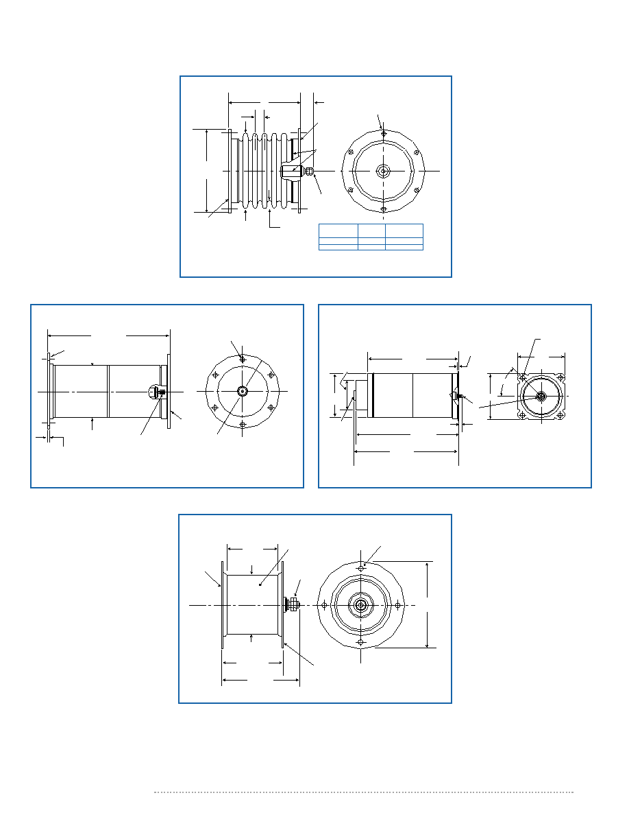
Standard Model Operating Characteristics
(1)
Type
Number
GPV-63
GPV-6301
GPV-6313
GPV-6322
GPV-7013
Static
Breakdown
Voltage
(2,7)
(Kilovolts)
65
50
100
65
40
Maximum
Peak
Current
(3)
(Kiloamperes)
50
50
60
60
20
Maximum
Conducted
Charge
per shot
(4)
(Coulombs)
0.5
0.5
0.5
0.5
0.3
Contains
Wall
Shield
(5)
(Y/N)
N
N
Y
Y
N
Contains
Mercury
(6)
(Y/N)
Y
Y
N
N
N
Typical
Operating
Voltage Range
(Kilovolts)
0.3 - 50
0.3 - 40
0.3 - 80
0.3 - 50
0.3 - 32
1.
The operating characteristics shown here are intended as an aid to prelimi-
nary gap selection. The characteristics listed are typical for the indicated
types under standard environmental conditions. The conditions found in
many applications will influence gap operating characteristics; therefore,
some characteristics may not be simultaneously achievable. Prospective
users of these gaps should be aware of the limitations in the data being pre-
sented. Contact PerkinElmer for information concerning the performance to
be expected in the intended application.
2.
SBV is the Static (Self) Breakdown Voltage. It is the dc voltage across the
main gap (between the opposite and adjacent electrodes, O-A) above which
the gap is likely to break down (conduct) with no trigger applied.
3.
The peak current applies for a critically damped discharge. Current reversals
degrade life, so gap operation in the underdamped condition should be
avoided when possible.
4.
In underdamped circuits, each current half-cycle contributes to the total con-
ducted charge, i.e., conducted charge increases independently of the direc-
tion of gap current. Therefore, the total conducted charge, including any "fol-
low-through" current, should not exceed the maximum conducted charge
indicated.
5.
Includes an internal shield to slow deposits of discharge debris on the insu-
lating ceramic.
6.
A small amount of metallic mercury is used in these gaps to aid in the forma-
tion of the initial discharge. These gaps should not be operated above 50∞C.
Care should be exercised in the handling and disposal of these gaps.
7.
Proper application of these gaps may require them to be immersed in insulat-
ing oil or gas depending on the operating voltage level and environmental
factors. A method to circumvent electrical breakdown across the outside sur-
faces of the ceramic insulators of the gap may be necessitated in some
uses. Some of the more important factors to consider in determining the
insulation qualities of the environment are altitude (local atmospheric
pressure); humidity; dust; cleanliness; temperature and pulsed versus
dc operation.
Notes
Environmental Specifications
Ambient temperature range
Operating temperature range
-54 to +100∞C without mercury, -54 to +50∞C with mercury
Nonoperating temperature range
-65 to +125∞C
Vibration
15 to 500 Hz at 10 g maximum
Shock
50 g, 11 milliseconds
Thermal Shock
-65 to +125∞C
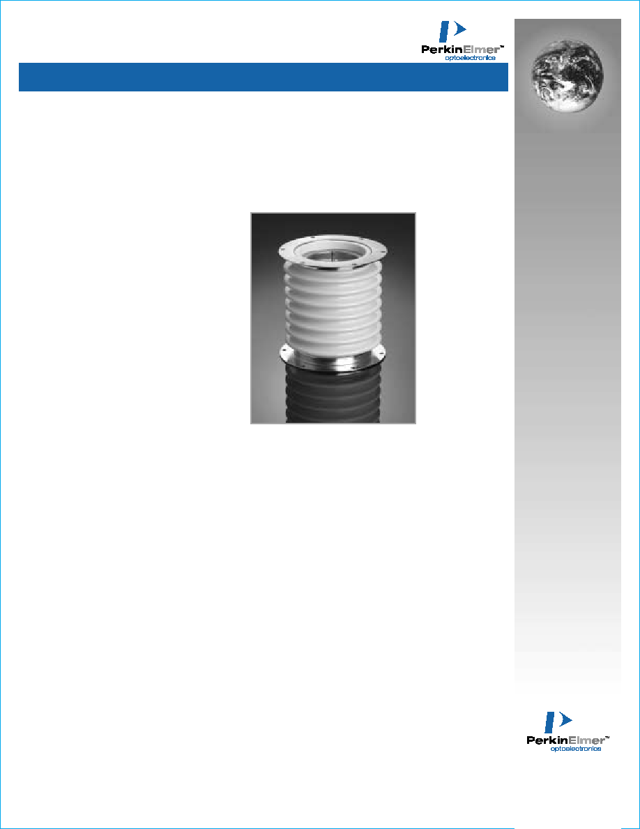
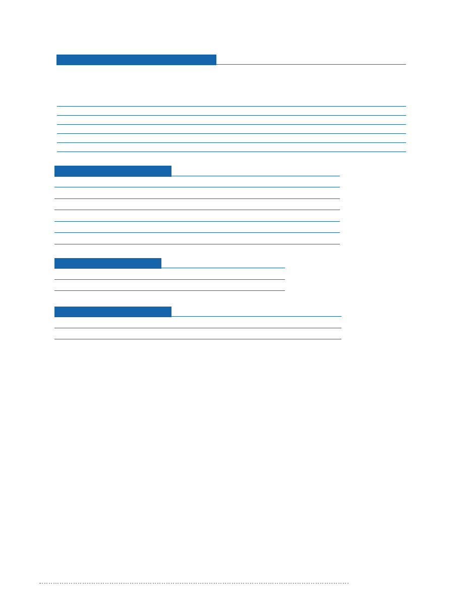
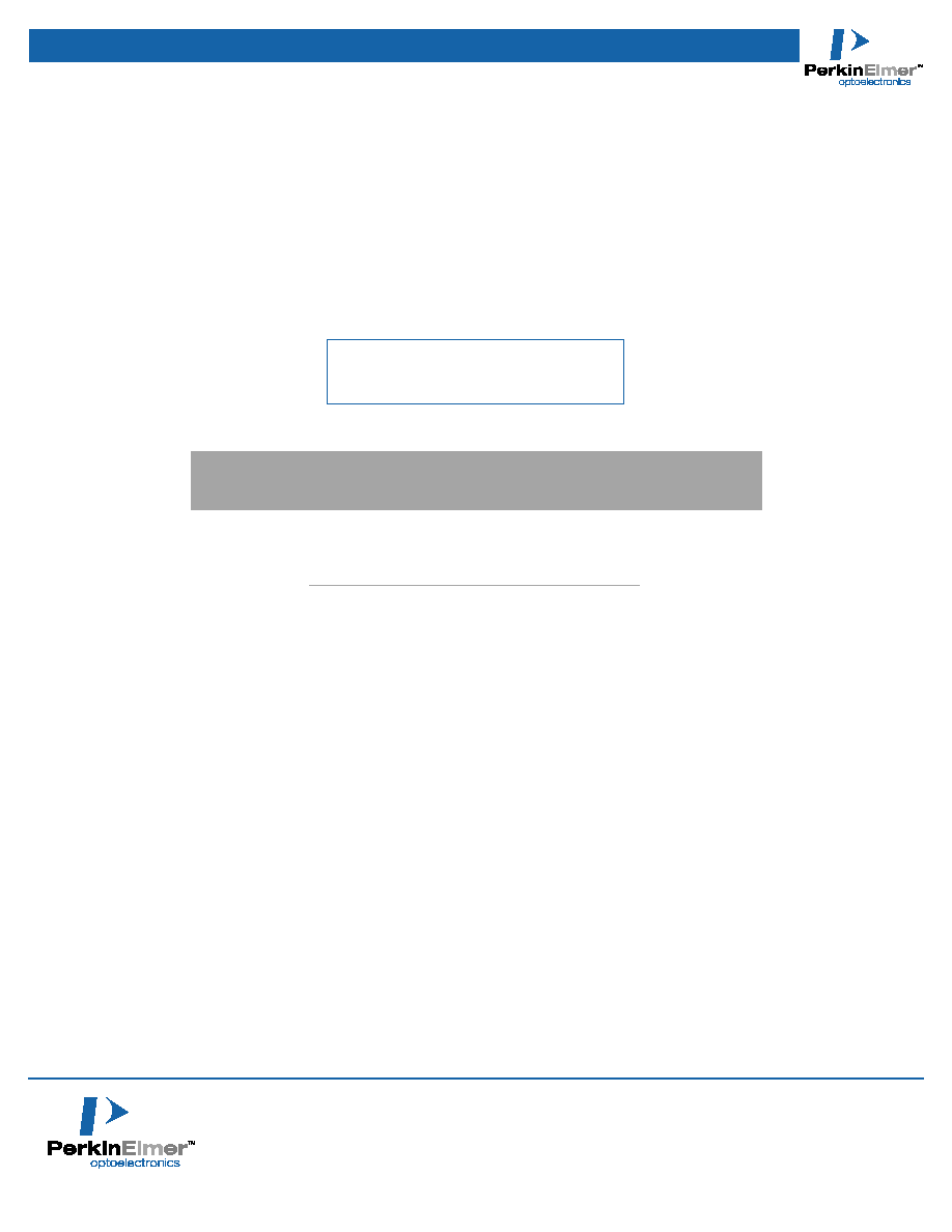
Mechanical Specifications
Envelope
Ceramic-metal, hermetically sealed, exposed metal parts nickel plated.
Torque applied to studs
6 inch-pounds maximum.
Electrical Specifications
Electrode capacity
Less than 5 pf.
Interelectrode resistance
Greater than 10
10
ohms at 500 V.
Triggered Vacume Gaps GPV-Series
* All values are nominal; specifications subject to change without notice.
To request additional information, receive a quote, or place an order, please contact PerkinElmer Optoelectronics at office listed below.
PerkinElmer Optoelectronics
35 Congress Street
Salem, MA 01970
Toll Free: (800) 950-3441 (USA)
Phone: (978) 745-3200
Fax: (978) 745-0894
Copyright © PerkinElmer
All rights reserved
Printed in U.S.A. 10/00
PerkinElmer is a registered trademark of PerkinElmer, Inc.
www.perkinelmer.com/opto
Our Quality and Environmental Policy
"Our goal is to supply our customers
the agreed quantity of specified products and services,
defect free and on time while conducting business
in an environmentally responsible manner"
Marking
PerkinElmer's trademark, part designation, and date code.
PerkinElmer welcomes inquiries about special types. We would be pleased to discuss the requirements
of your application and the feasibility of designing a type specifically suited to your needs.