Agilent HSDL-D100-001/002,
HSDL-D110-002
IrDA Smart Dongle
Data Sheet
Introduction
Agilent Smart Dongle is a
comprehensive hardware plus
software platform designed to
quickly enable wireless
Infrared communication. Smart
Dongle support wide range of
customizable IrDA applications
such as IrFM Financial
Payment services, picture and
music file transfers between
mobile devices, kiosk and
interactive posters data
distribution. It complies with
the IrDA SIR specification and
support data rate from
9600bps to 115.2kbps.
Smart Dongle position itself as
the comprehensive solution to
rapidly enable IrDA wireless
communication in devices.
Smart Dongle can be
customized into an IrFM
Smart Dongle for financial
payment applications, OBEX
Smart Dongle for music,
picture files or any generic
data file transfer application.
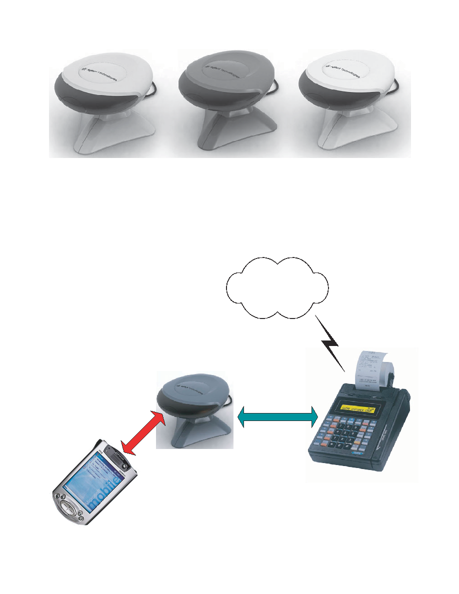
Agilent IrDA Smart Dongle
Family offers various hardware
plus software platforms to
meet different application
requirement and complexity.
HSDL-D100-001 Smart Dongle
is an entry-level solution
designed for simple object
transfers. It can be integrated
into devices, such as musical
instruments to provide
wireless connectivity for music
sharing with mobile phones.
The more sophisticated HSDL-
D100-002 and HSDL-D110-002
have greater computing-power
and memory resources for
more complex and versatile
applications, like IrFM
financial payment services.
Agilent IrDA Smart Dongles
are bundled with user-friendly
"Smart Dongle Flash Utility"
that facilitates On-the-fly
firmware updating in 6 easy
steps from a PC. Easy
firmware updating allows
Smart Dongles to be readily
upgraded even after product
market release.
The HSDL-D100-001 and
HSDL-D100-002 comes with in
sub-assembly Printed Circuit
Board (PCB) module, while
the HSDL-D110-002 comes
complete in stylish mechanical
casing.
System Overview
Agilent IrDA Smart Dongles
are microcontroller-based
standalone system, complete
with standard embedded IrDA
protocol stack with IrOBEX
and support optional
application programs such as
the IrFM Profile, OBEX Server
and OBEX Client. Smart
Dongles handle IrDA
communication between
interfacing terminals
transparently, without the
need for constant host
supervision.
Smart Dongles are connected
to host terminals using 3-wire
Null-Modem serial interface.
The Serial Interface connection
is used for transferring data
as well as command and
control. The serial interface is
also used for firmware
updating from a connected PC
with the Smart Dongle Flash
Utility.

2
HSDL-D100-001 Smart Dongle
The HSDL-D100-001 Smart
Dongle uses a small form-
factor, single chip MCU
solution for basic standard
application such as data object
transfer using the IrOBEX
Profile. It comes with two
memory options: 2KB RAM +
32KB Flash (standard), and
4KB RAM + 64KB Flash
(optional). Figures 1 and 3
show the HSDL-D100-001
Smart Dongle System Block
Diagram and Software
Structure, respectively.
The HSDL-D100-001 software
supports core IrDA protocol
stack, IrOBEX, and basic host
serial interface software
module. Core IrDA protocol
stack handles low-level baud
rate negotiation, exchange of
connection configuration
parameters, data integrity
check, link management etc,
relieving host terminal from
such low-level IrDA
transaction.
This platform is equipped with
a 3-wire Serial Interface Port
(UART) for interfacing to a
host device. Table 1 and
Figure 2 show the pin
definitions for HSDL-D100-
001. TXD and RXD pins are
designed for direct connection
to UART port of host system.
Pin signals do not go through
a Level Shifter nor provide
RS-232 compliant voltage.
The power is supply from the
host system through the +3.3V
connector pin.
HSDL-D100-001 Smart Dongle
support a range of host
interface communication speed
(baud rate) from 9600bps to
115.2kbps.
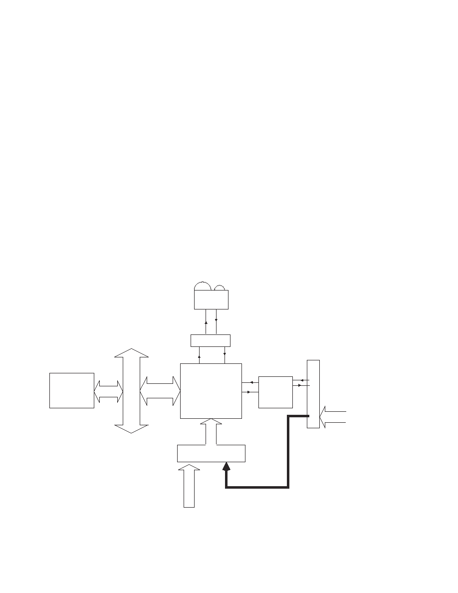
Figure 1. HSDL-D100-001 Smart Dongle Hardware Block Diagram
Figure 2. HSDL-D100-001 Smart Dongle PCB Layout and Interface Connection
8-bit
Microcontroller
Unit (MCU)
Asynchronous Serial
Interface To Host
Bus Power
IrDA
Transceiver
IR
TXD
IR
RXD
TXD
RXD
GND
+3.3V DC
20 (mm)
20 (mm)
GND
NC
TXD
RXD
+3.3V
NC
3
Table 1. HSDL-D100-001 Smart Dongle interface signal with host system
Signal Connection
Description
TXD
RXD
+3.3V
GND
NC
No Connection
Common System Ground with host
Bus Power Supply DC +3.3V
Receive Pin (with respect to Smart Dongle) for serial interface to host
Transmit Pin (with respect to Smart Dongle) for serial interface to host
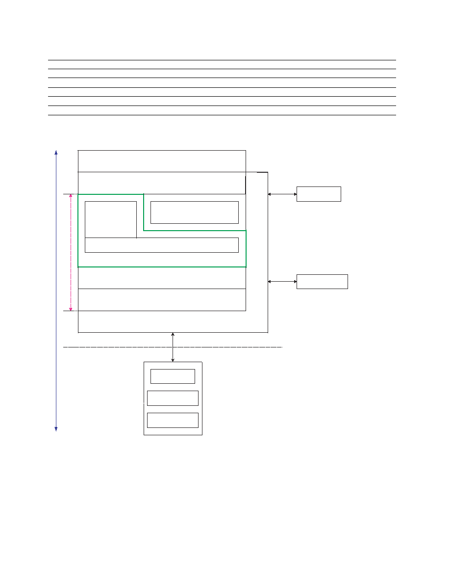
Figure 3. HSDL-D100-001 Smart Dongle Software Structure
Applications
TinyTP
LM-IAS
LM-MUX
IrLMP
IrLAP
SIR Driver / Framer
Physical Drivers
Physical Drivers
Host Interface
UART
System Timer
System
Resources
Core IrDA Protocol Stack
Hardware Dependency
Low
High
IrDA UART
IrDA Transceiver
ENDEC
SIR IrDA Port
Physical Hardware
IrOBEX
4
HSDL-D100-002 / HSDL-D110-002
Smart Dongle
The mid-end HSDL-D100-002/
HSDL-D110-002 Smart Dongle
uses ARM7TDMI MCU solution
with a default 256KB flash
memory and 32KB program
memory on chip. 512KB flash
memory is optional and a
further RAM expansion option
allows 128KB or 512KB to be
added. Figure 4 and 5
illustrate the System Block
Diagram and Software
Structure respectively for the
mid-end HSDL-D100-002/
HSDL-D110-002 Smart Dongle.
The platform supports core
IrDA protocol stack, IrSock,
IrOBEX, IrFM, host serial
interface software module and
a wide range of user
applications. Core IrDA
protocol stack relieve host
system of baud rates
negotiation, connection
configuration exchange, data
integrity check, link
management and other low-
level IrDA transaction.
Note that the standard
applications embedded in
HSDL-D100-002 and HSDL-
D110-002 include the Core
IrDA Protocol Stack and
IrOBEX for simple file transfer
operation.
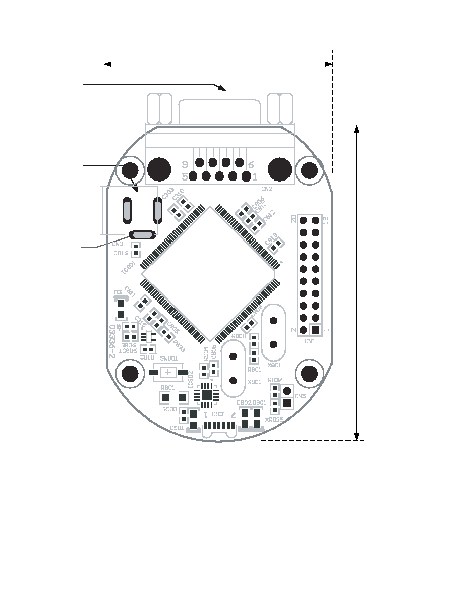
The HSDL-D100-002/HSDL-
D110-002 Smart Dongle comes
with a RS-232 compliant serial
port, using the 3-wire
interface through a RS-232
Level Shifter. This serial port
can be connected to a typical
Male DB9 connector (shown in
Figure 6), or to a 2.54mm
pitch, 90
∫
Bend Header as
illustrated in Figure 6. Table 3
illustrates the interface signal
for HSDL-D100-002 and
HSDL-D110-002.
Figure 4. HSDL-D100-002/ HSDL-D110-002 Smart Dongle Hardware Block Diagram
32-bit ARM7TDMI
MCU
ENDEC
RS232
Level
Shifter
IrDA
Transceiver
Optional
128KB/256KB
SRAM
ADDRESS BUS
/DATA BUS
IR TX
D
IR RXD
TXD
RXD
Power & Reset Circuitry
DB9
Connector
TXD
RXD
External +5V
DC Supply
from DC Jack
+5V DC
Bus Power
A range of host interface baud
rates from 9600bps to
115.2kbps is supported. Host
interface baud rate is specified
by configuring Jumper Setting
located on the bottom side of
the PCB as illustrated in
Figure 7. Table 2 illustrates
the Jumper setting for the
supported baud rate. The
serial port is also used for
firmware update. Description
on the firmware update will
be presented in the Smart
Dongle Flash Utility Section.
Bus Power can be supplied
from the host system to the
"Bus Power" pin through the
DB9 connector or the 2.54mm
pitch, 90
∫
Bend Header.
Alternatively, power can also
be supplied through the DC
Jack connector.
5
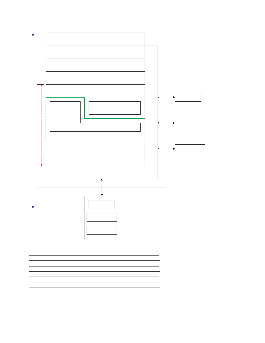
Applications
Core IrFM Protocol (CIP)
IrOBEX
IrSock
IrDA Protocol Stack Interface
TinyTP
LM-IAS
LM-MUX
IrLMP
IrLAP
SIR Driver / Framer
Physical Drivers
Physical Drivers
Host Interface
UART
IrDA Dispatcher
System Timer
Physical Hardware
System
Resources
Core IrDA Protocol Stack
Hardware Dependency
Low
High
IrDA UART
IrDA Transceiver
ENDEC
SIR IrDA Port
Physical Hardware
Table 2. Jumper setting for setting Host Interface baud rate
Notes:
1. Open ≠ Leave the Jumper pad as open circuit
2. Close ≠ Short the Jumper pad with a 0
(0603 Case Size) resistor
3. Setting other than those defined in Table 2 put the communication link into an indeterminate state.
4. The baud rate jumper setting have no effect during firmware update.
Baud Rate (bps)
R803
R805
R807
9600 (Default Setting)
Open
Open
Open
19200
Open
Close
38400
Close
Open
57600
Close
Close
115200
Close
Open
Open
Open
Open
Open
Figure 5. HSDL-D100-002/ HSDL-D110-002 Smart Dongle Software Structure for IrFM Application
6
Figure 6. HSDL-D100-002/ HSDL-D110-002 Smart Dongle Top Layer PCB Layout and Interface Connection
Male DB9
Connector
46mm (Approximate)
65m
m
(A
pproxi
m
a
t
e
)
DC Jack
Footprint
GND
Slot 1x3mm

7
Table 3. HSDL-D100-002/ HSDL-D110-002 Smart Dongle DB9 interface signal with host system
DB9
Connector
Signal Connection
Description
1
2 RXD
3
TXD
4
5
GND
System Ground from host system
6
7
8
Programming
This pin is used for updating the firmware and should be left open.
Do Not Connect any signal to this pin during normal operation.
Operation is not guaranteed when this pin is connected to this signal.
9
Bus Power
Power supply from Host system DC+5V ~ DC+8V
NC
NC
NC
NC
Receive Pin (with respect to Smart Dongle) for serial interface to host
Transmit Pin (with respect to Smart Dongle) for serial interface to host
No Connection
No Connection
No Connection
No Connection
Bus Power GND RXD
TXD
Programming
2.54mm Pitch
90∫ bend
Header
footprint
R803
R805
R807
Figure 7. HSDL-D100-002/ HSDL-D110-002 Smart Dongle Bottom Layer PCB Layout and Interface Connection
8
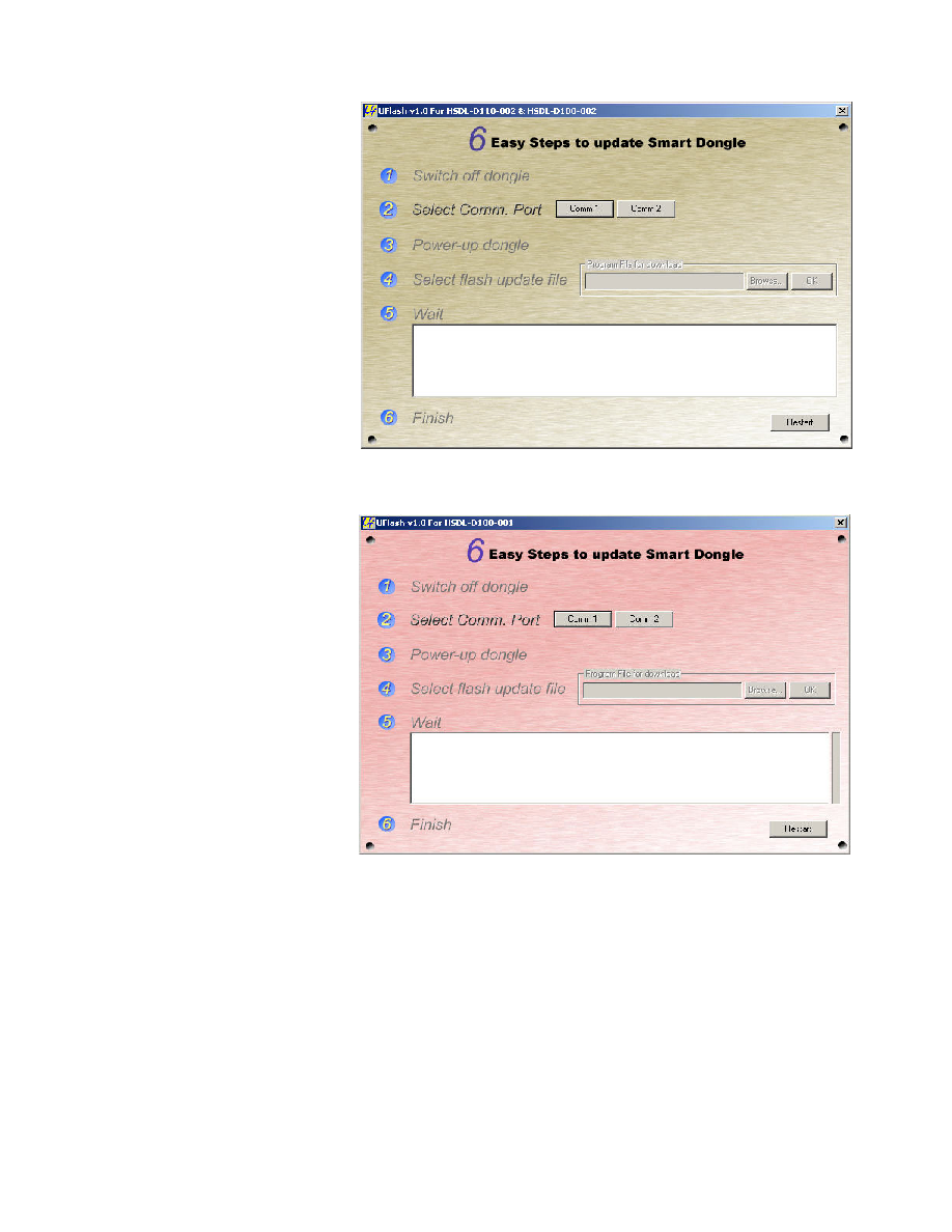
Figure 8. Screen shot of the HSDL-D100-002/HSDL-D110-002 Smart Dongle Flashing Utility
Smart Dongle Flash Utility
Agilent IrDA Smart Dongles
feature On-the-fly Firmware
Updating through a Host
Interface UART with the
external DC Jack power
supply.
The Smart Dongle Flash Utility
works on Windows 2000/NT/
XP PC. It updates Smart
Dongle firmware through the
PC RS-232 serial port. There
are two versions of the flash
utility ≠ one for HSDL D100-
002 & HSDL D110-002 (see
figure 8), another for HSDL
D100-001 (see figure 9).
Smart Dongle Flash Utility is
designed for ease of use. A
six-steps updating procedure
can easily be performed by
end-user. Smart Dongle has a
firmware corruption protection
feature. In the event of a
power failure during firmware
updating, Smart Dongle can
reliably restart and set to
programming state, when
updating can be tried again.
Figure 9. Screen shot of the HSDL-D100-001 Smart Dongle Flashing Utility

9
Notes:
1. External RAM is optional. Not included in standard package.
2. Applicable only to sub-assembly module.
3. For Asynchronous Serial Interface, RS-232 Level Shifter IC and DB9 connector are excluded.
4. Max Windows Size varies between applications and available memory.
5. Max Data Size varies between applications and available memory.
6. For HSDL-D100-001 Smart Dongle, application has no access to the IrSock APIs, as this layer will not be available in the dongle protocol stack.
Application needs to be highly customized to provide IrOBEX compatibility. Moreover, due to limited memory, the dongle is suitable for basic
application such as OBEX file transfer with limited room for future upgrading/enhancement.
7. The link distance indicated does not take into account influence of windows design.
8. Hardware optional accessories, which is not included in the standard package, might be needed.
Table 4. Comparison between HSDL-D100-002/HSDL-D110-002 and HSDL-D100-001 Smart Dongle
Specification
Mid-End Smart Dongle
HSDL-D100-002/
HSDL-D110-002
Low-End Smart Dongle
HSDL-D100-001
Remarks
Hardware Platform
32-bit ARM7TDMI MCU
8-bit CISC MCU
Internal Flash Memory
256KB / 512KB(Max)
32KB / 64KB(Max)
64KB Flash is optional
Internal RAM Size
32KB
2KB / 4KB(Max)
4KB RAM is optional
CPU Operating Speed
29.4912MHz
18.432MHz
RAM Expansion Option
128KB / 512KB(Max)
None
Note 1
Typical Operating Voltage
DC +7.5V
(DC Jack or Bus Power)
DC +3.3V
(Bus Power)
Max Operating Voltage
+8V
Fixed +3.3V
Min Operating Voltage
+5V
Fixed +3.3V
Operating Current
100mA (Max)
50mA (Max)
IrDA Range
30cm
30cm
Note 7
PCB Board Size
46mm x 65m
(Approximate)
20mm x 20mm
Note 2
Mechanical Casing Included
For HSDL-D110-002 only
No
Host Interface
Note 3
On-the-fly firmware upgrade
Flash from PC with
RS-232. Note 8
IrDA Speed (SIR)
9.6/19.2/38.4/57.6/115.2
(kbps)
9.6/19.2/38.4/57.6/115.2
(kbps)
Windows Size
Variable: 1,2,3,4,5,6 or 7
Fix: 1
Note 4
Data Size
Variable: 64, 128, 256, 512
or 1024 bytes
Variable: 64, 128 or 256
bytes
Note 5
IrSock Supported
Note
6
IrOBEX
Supported
IrFM
Supported
IrDA Software Characteristics
Supported (Optional)
Not Available
Not Available
3-wire RS-232 compliance
with DB9 Male Connector
or Standard 2.54mm pitch,
90' Bend Header
3-wire Asynchronous
Serial Interface Standard
2x3 1.27mm pitch,
90' Bend Header
Yes. Bundled with Smart
Dongle Flash Utility
Yes. Bundled with Smart
Dongle Flash Utility

10
Product Features
HSDL-D100-001
Supply Voltage: Regulated +3.3V
Operating Current: 50mA(Max)
System Clock: 18.432 MHz
SIR IrDA Data Compliant 115.2kbps
Controller
8-bit Microcontroller
Memory
32KB On-chip Flash ROM (Standard)
2KB On-chip SRAM
OR
64KB On-chip Flash ROM (Optional)
4KB On-chip SRAM
Peripherals
Microcontroller with dual UARTs and IrDA Interface
IrDA transceiver compliant to Physical Layer Specifications version 1.4
Low Power
Operating Temperature
0
∞C To 70∞C Celsius
Host Interface
3-wire Null Modem RS232 port
Baud Rate ≠ Standard 9600bps, Maximum 115.2kbps
Data Size - 8-bit data
Parity - No parity bit
Stop Bit - 1 stop bit
Standard Software
Core IrDA Protocol Stack with basic IrOBEX file transfer application.
HSDL-D100-002/ HSDL-D110-002
Supply Voltage: DC +5V to +8V
Operating Current: 100mA(Max)
System Clock: 29.4912MHz
SIR IrDA Data Compliant 115.2kbps
Controller
32-bit ARM Microcontroller Unit
Memory
256KB On-chip Flash ROM (Standard)
32KB On-chip SRAM
OR
512KB On-chip Flash ROM (Optional)
32KB On-chip SRAM
Peripherals
Microcontroller with dual UARTs
IrDA transceiver compliant to Physical Layer Specifications version 1.4
Low Power
Operating Temperature
0
∞C To 70∞C Celsius
POS/CAT Host Interface 3-wire Null Modem RS232 port
Baud Rate ≠ Standard 9600bps, Maximum 115.2kbps
Data Size - 8-bit data
Parity - No parity bit
Stop Bit - 1 stop bit
Standard Software
Core IrDA Protocol Stack with basic IrOBEX file transfer application.
11
Application Notes: Implementing
HSDL-D100-002/ HSDL-D110-002
Smart Dongle for IrFM
HSDL-D100-002/ HSDL-D110-
002 Smart Dongle can be
customized to a wide range of
devices including IrFM
application. In IrFM
application, Agilent Smart
Dongle replaces the physical
card reader that connects to a
POS. Figure 10 shows Smart
Dongle being used in an IrFM
setup.
The IrFM (Infrared Financial
Messaging) profile is a quick
and seamless digital payment
system for infrared enabled
devices and Point of Sales
(POS) Terminals. Financial
payment begins by beaming
Figure 10. A typical application setup of the IrFM Smart Dongle in proximity payment
Point Of Sale Terminal
(POS)
IrFM Smart Dongle
Terminal
3-wire Null Modem
RS-232 Interface
Payment Network
Personal Trusted Device
(PTD)
Wireless IrDA Link
electronic credit card
information from mobile
devices like from mobile
phones and Personal Digital
Assistants (PDA). Digital
receipt is then issued and
consumer can manage them
with Personal Financial
Management Tools.
IrFM version of Agilent IrDA
Smart Dongle can be
customized for such financial
payment. Smart Dongle can
handle IrFM services
internally, requiring no
modification of POS host
terminal to enable existing
Point of Sale (POS) terminals.

12
Software Architecture for IrFM Application
The IrDA protocol stack is developed in layers, with API service for each layer of the infrared
communication protocols. Figure 7 shows an overview of IrFM customized Smart Dongle software
architecture. The IrFM software system consists of the following:
∑
IrDA Port
The physical IrDA port provides a continuous, bidirectional communication up to 30 cm with
30degree half angle cone. Communication speed varies between 9600bps to 115.2kbps with the
data packet validation by software CRC-16.
∑
Physical Driver
A set of low-level functions are provided to control and configure the hardware such as the
HSDL-3208 IrDA Transceiver, 16550 Compatible UART with ENDEC etc.
∑
IrDA Base Protocol Layers
IrDA Base Protocol Layers consists of the following layers:
∑
IrLAP
Provides a reliable device-to-device connection for reliable ordered transfer of data
between two IrDA devices. This protocol is a variant derived from the multi-drop HDLC
protocol that manage information exchange, connection/disconnection, resolve address
conflict, discovery to identify other devices and sniffing for devices to connect to.
∑
LM-IAS
Maintains an information database for the IrDA device to identify itself to other IrDA
devices on the services it offers and looks for another compliant IrDA device as well.
∑
LM-MUX
Provides multiple links over a single IrLAP.
∑
TinyTP
TinyTP provides a flow control mechanism, segmentation and reassembly of data packets
for each transport connection created.
∑
IrSock
This layer serves as an interface for higher layer application to access the underlying IrDA
protocol stack..
∑
OBEX
Provides generic Object Exchange services to the application to support IrOBEX operations
such as CONNECT, PUT, GET, SETPATH, ABORT and DISCONNECT. This layer is required for
implementing the IrFM Point and Pay Profile.
∑
Core IrFM Protocol (CIP)
Provides the IrFM Services with a set of primitives and corresponding data object that
conforms to the CIP specifications, for data to be exchanged between the POS and PTD
devices.
∑
Applications (IrFM Service)
This layer provides IrFM services to user application.
13
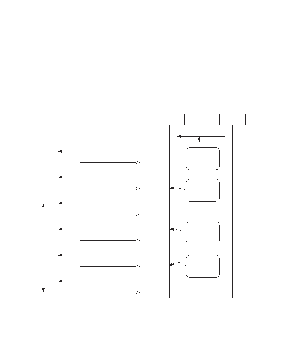
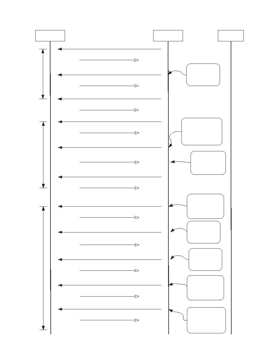
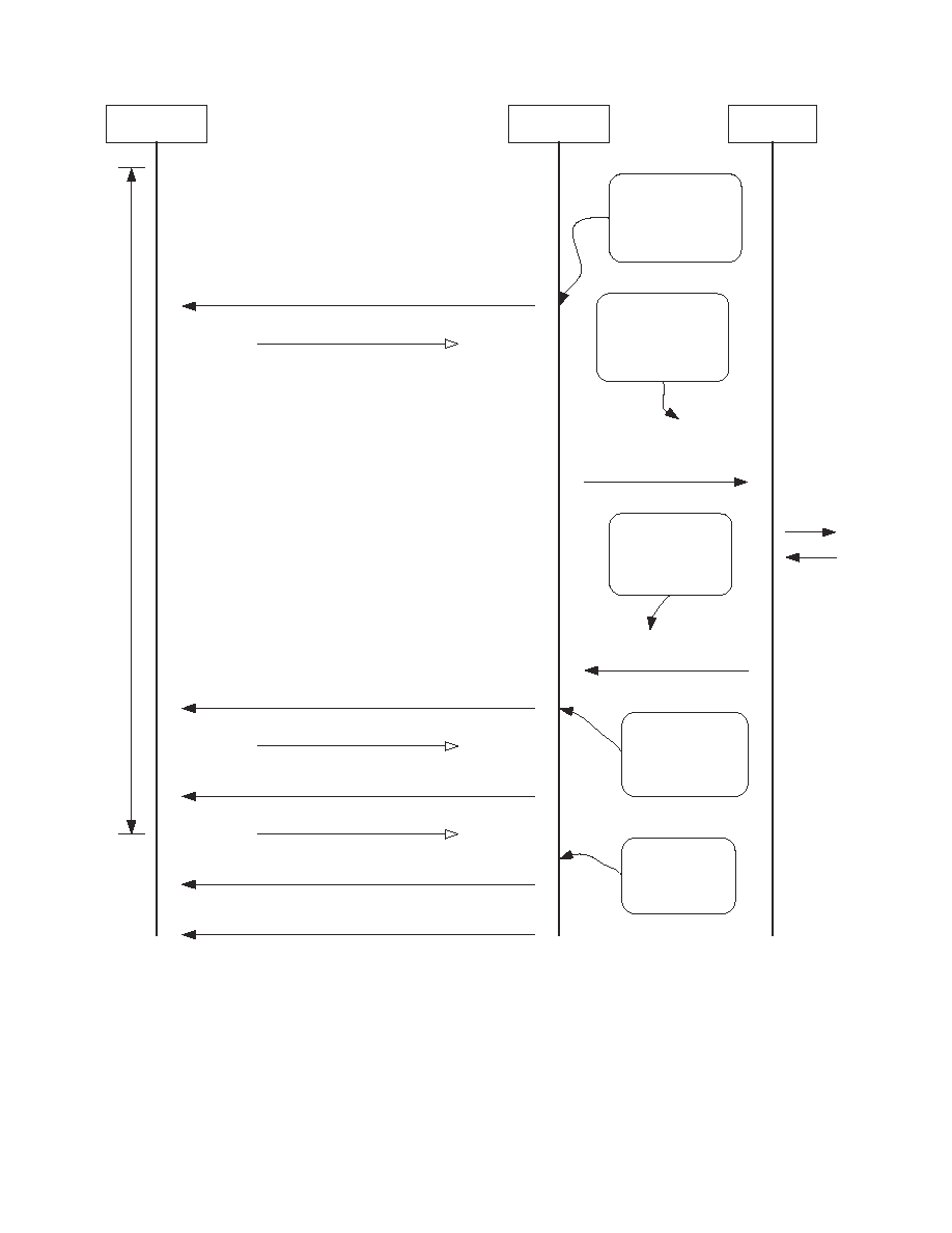
IrFM Transaction Flow
Figure 11 illustrates a typical
the transaction flow for an
IrFM Transaction among the
Personal Trusted Device,
Smart Dongle and the POS/
CAT Terminal.
Sale transaction starts with
the POS initiates an IrFM
transaction with a customer's
PTD through the Smart Dongle
by sending the purchasing
amount to the Smart Dongle.
The Smart Dongle establish a
reliable IR connection, that is
capable of resuming a session
without the lost of data when
the underlying transport layer
(i.e. IrLAP Link) is temporary
broken. This is accomplished
by employing the OBEX
Session Protocol.
After a successful OBEX
Session has been setup, the
Smart Dongle and customer's
PTD complete the IrFM
transaction by using a set of
Core IrFM Service.
A soft copy of the digital
receipt is beamed to the
customer's PTD for verification
and tracking at the end of
IrFM transaction.
Figure 11. A Typical IrFM Transaction Flow (part 1)
PTD
IrFM Smart
Dongle
POS/CAT
1. CIPCreateInstance()
SUCCESS
2. CIPCreateObexSession()
Purchase Price
SUCCESS
3. CIPCreateConnection(CORE_IRFM_UUID)
SUCCESS
4. CIPPrimitives(CUSTOMER_DATA)
SUCCESS: Customer Data
5. CIPPrimitives(MERCHANT_DATA)
SUCCESS
6. CIPCloseConnection()
SUCCESS
Exchange_Info Transaction
of C
o
re IrF
M S
e
rvice
Sale Transaction
started with POS
sending the price of
purchase to IrFM
Smart Dongle
Smart Dongle initiate
an OBEX Session
connecting to
customer's PTD
device
Smart Dongle connect
to Core IrFM Service
and query customer
info (e.g Name) from
PTD
Smart Dongle identify
itself to PTD by
sending store name,
location , registeration
number etc
14
PTD
IrFM Smart
Dongle
POS/CAT
10. CIPCreateConnection(CORE_IRFM_UUID)
SUCCESS
11. CIPPrimitives(PAYMENT_OPTION)
SUCCESS: SELECTED_OPTION_PAYMENT_UUID
12. CIPCloseConnection()
SUCCESS
Get_Desired_Payment_Option
of C
o
re IrF
M S
e
rvice
13. CIPCreateConnection
(SELECTED_OPTION_PAYMENT_UUID)
SUCCESS
14. CIPPrimitives(MERCHANT_DATA)
15. CIPPrimitives(TRANSACTION_INFO)
SUCCESS
SUCCESS
16. CIPPrimitives(ALGORITHM_ID)
SUCCESS
17. CIPPrimitives(KEY_DATA)
SUCCESS: KEY
...
IrF
M P
a
yment S
e
rvices
Smart Dongle sends
available payment options
to PTD for selection. E.g
Credit (VISA, Master,
AMEX etc), Debit,
E-CASH, E-CHECK etc
Smart Dongle retrieves
payment option
selected by customer.
Payment Option now
identify by new UUID
Smart Dongle connects
to customer PTD
specific IrFM Payment
Service using selected
Payment Option UUID
Smart Dongle identify
itself to PTD by
sending store name,
location , registeration
number etc
Smart Dongle send
transaction price,
date, time etc to PTD
for customer
verification
Smart Dongle sends
Algorithm ID to identify
the transaction security
algorithm to be used
Smart Dongle acquires the
key data that is used to
exchange transaction
encryption key
information from PTD
7. CIPCreateConnection(CORE_IRFM_UUID)
SUCCESS
8. CIPPrimitives(TRANSACTION_INFO)
SUCCESS
SUCCESS
9. CIPCloseConnection()
P
u
t
_
P
r
i
ce Transact
i
o
n
of C
o
re IrF
M S
e
rvice
Smart Dongle send
transaction price,
date, time etc to PTD
for customer
verification
Figure 11. A Typical IrFM Transaction Flow (part 2)
15
PTD
IrFM Smart
Dongle
POS/CAT
18c. APPROVED:
Digital Receipt
18. CIPPrimitives(PAYMENT)
SUCCESS: Customer's Payment Info
19. CIPPrimitives(SHORT_TRANSACTION_LOG)
SUCCESS
20. CIPCloseConnection()
SUCCESS
18a. Forward customer's
payment info to POS
terminal
21. CIPCloseObexSession()
22. CIPCloseInstance()
-- Sale Transaction Completed --
........
IrF
M P
a
yment S
e
rvices
Smart Dongle requests
payment specific info
such as Credit Card
number, expiry date,
holder name etc from
PTD
Smart Dongle forwards
retrieved customer's
payment info to POS for
online processing/
verification
Upon getting Approval
from Financial
Insitution , POS send
approval code with
receipt to Smart Dongle
Smart Dongle beams the
Digital Receipt to
customer's PTD for
verification and tracking
Smart Dongle
terminates and closes
connection with
customer's PTD
18b. POS
getting
approval
online
Figure 11. A Typical IrFM Transaction Flow (part 3)

www.agilent.com/
semiconductors
For product information and a complete list
of distributors, please go to our web site.
For technical assistance call:
Americas/Canada: +1 (800) 235-0312
or (408) 654-8675
Europe: +49 (0) 6441 92460
China: 10800 650 0017
Hong Kong: (+65) 6756 2394
India, Australia, New Zealand: (+65) 6755 1939
Japan: (+81 3) 3335-8152(Domestic/Inter-
national), or 0120-61-1280(Domestic Only)
Korea: (+65) 6755 1989
Singapore, Malaysia, Vietnam, Thailand,
Philippines, Indonesia: (+65) 6755 2044
Taiwan: (+65) 6755 1843
Data subject to change.
Copyright © 2004 Agilent Technologies, Inc.
April 6, 2004
5989-0865EN