
www.perkinelmer.com/opto
LC3000-Series
High Performance, Low-Cost Analog Line Scan Camera
512, 1024 and 2048 elements, 10 and 20 MHz output rates
Description
In the LC3000-series analog line scan
camera, PerkinElmer has combined
the best features of photodiode array
detection, high-speed charge-coupled
scanning, and analog line scan camera
technology to offer an uncompromising
solution to the increasing demands of
advanced imaging applications.
The LC3000-series is a high
performance, low-cost, analog line scan
camera line. The LC3000-series features
a differential driver analog video out-
put with resolutions of 512, 1024 or
2048 pixels, which can achieve data
rates of up to 20 MHz with exceptional
noise immunity. They are designed for
volume applications where small size
and low cost are required.
In order to allow the user to compen-
sate for variations in illumination
found in "real-world" application
environments, the cameras feature
adjustable gain and offset levels. The
LC3000-series cameras feature a
Features
∑
10 and 20 MHz output rate models
∑
Geometrically precise 14 µm square
pixel CCD
∑
Small size: 2.5"H x 2.5"W x 2.72"L
∑
High dynamic range (500:1)
∑
Peak QE greater than 65%
∑
Antiblooming control
∑
Single power supply operation
∑
Electronic exposure control
∑
Adjustable gain and offset levels
∑
Line scan rates to 36 kHz
geometrically precise photodiode CCD
image sensor with 14µm square photo-
elements. State of the art electronic
design enables the LC3000-series to
deliver consistent, reliable performance
while the sturdy metal housing provides
maximum protection in a variety of
harsh environment and factory
floor conditions.
The LC3000-series cameras convert
light imaged during a scene into an
analog video signal. The amplitude of
the video signal is a linear function of
the incident illumination taken from the
scene. Antiblooming structures within
the sensor ensure superior performance
over a wide range of lighting conditions.
User-defined control is possible for
line rate, integration time and
video data rate.
LC3000 cameras may be interfaced
to most frame grabber cards, allowing
for a tested, plug and play solution.
Typical high performance line scan
DA
T
ASHEET
Lighting
Imaging
Telecom
Imaging Product Line
Æ
DSP-201.01D - 4/2002 Page 1
12586 Final Art 2 5/9/01 4:51 PM Page 1

Figure 1a: Spectral Sensitivity Curve (Min. Gain)
100
90
80
70
60
50
40
30
20
10
0
100
90
80
70
60
50
40
30
20
10
0
250
350
450
550
650
750
850
950
1050
Right Scale
Left Scale
Responsivity (V/
µ
J/cm
2
)
QE (%)
Wavelength (nm)
Figure 1b: Sensor Window Transmission Curve
0
150
250
350
450
550
650
750
850
950
1050
10
20
30
40
50
60
70
80
90
100
Wavelength (nm)
T
ransmission (%
)
Analog Line Scan Camera
www.perkinelmer.com/opto
DSP-201.01D - 4/2002 Page 2
Table 1. Master/Slave Mode DIP-switch Settings
DIP Switch #1 Setting
DIP Switch #2 Setting
Operating Mode
ON
ON
Master Mode
OFF
OFF
Slave Mode
OFF
ON
Alternate Slave 1
ON
OFF
Alternate Slave 2
Description (cont.)
applications include lumber processing,
parcel scanning, non-contact measure-
ment, document scanning, dimensional
gauging, biomedical imaging, bar code
scanning and many other industrial
and scientific applications.
The Sensor
The LC3000-series cameras contain
a high-performance, high-resolution
line scan image sensor (PerkinElmer
Optoelectronics parts RL0512PAG,
RL1024PAG, or RL2048PAG) featuring
a pinned photodiode pixel. Each
photodiode converts incident light into
discrete charge packets. Advantages of
pinned photodiode pixels include lin-
ear exposure control, the elimination
of image lag, and the reduction of
photo response non-uniformity (PRNU).
For more specific sensor specifications
and information, please consult the
appropriate sensor datasheet. Figure 1a
details the spectral sensitivity of the
sensor, while Figure 1b details the
sensor's glass window light trans-
mission curve.
Functional Description
The video signal from the sensor is
processed through a single channel of
sampled-and-held, raster order, analog
video data. The video channel signal
processing circuitry offers both
adjustable gain and offset levels to
allow customization of the camera to
unique lighting applications. An
operational amplifier in a differential
configuration is recommended to
receive the video signal. Figure 2
details the camera video processing.
Operating Modes
The LC3000-series cameras can be
operated in one of two different modes:
Master Mode and Slave Mode. Master
mode is to be used when the LC3000-
series camera is operating as a stand-
alone unit. Master mode requires
only input DC power (12-24 VDC) for
operation. In this mode of operation,
the camera will operate at its basic
clock frequency (defined by the model
number) and at the maximum line rate.
Master mode operation is selected
using the bank of rear-camera located
12586 Final Art 2 5/9/01 4:51 PM Page 2
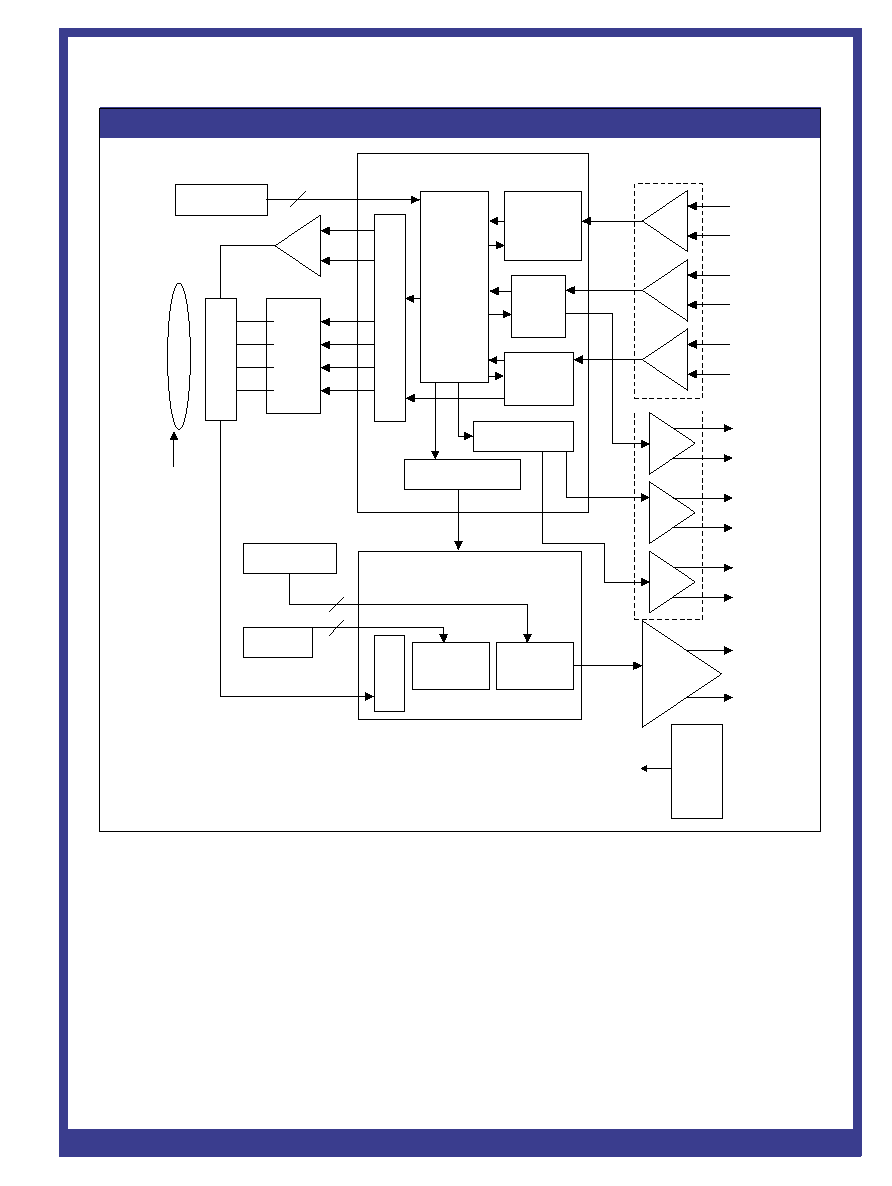
Figure 2: LC3000 Camera Block Diagram
RS-422 Receivers
+LT
-LT
+MCLK
-MCLK
+LRn
-LRn
+CCLK
-CCLK
+CLT
-CLT
+LEN
-LEN
Line Enable Logic
VSP TIMING LOGIC
OFFSET
CONTROL
Single
D.C
Power
Supply
Input
12-24V
CAMERA
TIMING
LOGIC
Dip Switch
Position 1 and 2
LINE
TRANSFER
LOGIC
CLK
LOGIC
Exposure
Control
Logic
GAIN
CONTROL
Amp
+V
out
-V
out
LENS
Dip Switch
Position 3-5
Dip Switch
Position 6-8
Offset Range Select
Gain Range Select
Camera Mode Select
L
E
V
E
L
T
R
A
N
S
I
M
A
G
E
R
C
D
S
D
R
I
V
E
L
O
G
I
C
VIDEO SIGNAL
PROCESSING
FPGA
2
RS-422 Drivers
ÿTG
ÿPG
ÿRG
ÿAB
ÿH2
ÿH1
3
3
Analog Line Scan Camera
www.perkinelmer.com/opto
DSP-201.01D - 4/2002 Page 3
DIP-switches. These switches are
accessible behind a removable panel,
located above the 25-pin connector on
the back plate of the camera. Figure 3
illustrates the timing details in Master
Mode.
Slave Mode is to be selected when the
camera's operations are to be synchro-
nized with the user's unique system.
In slave mode, the camera requires an
external Master Clock signal (MLCK)
to define the output video data rate,
as well as a properly timed Line
Transfer (LT) signal to initiate the line
readout. Figure 4 illustrates timing
details in slave mode. Table 1 details
correct DIP-switch settings for both
Master and Slave Mode.
Within slave mode, there are two
alternative settings for unique appli-
cations. Alternative Slave Mode 1
allows the user to supply the camera
with Line Reset (LR) and LT signals,
but allows the camera to run at the
maximum data rate determined by the
internal oscillator. Alternative Slave
Mode 2 instructs the camera to ignore
LR signals, which allows users to
bypass the exposure control feature
of the camera. Table 1 details all DIP-
switch settings for all operating
modes.
12586 Final Art 2 5/9/01 4:51 PM Page 3
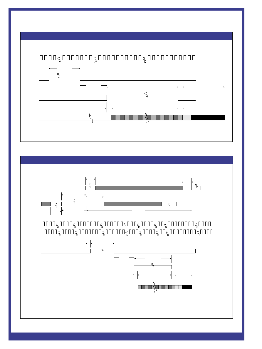
Figure 3: Master Mode Timing Diagram
CCLK
CLT
LEN
Analog
Video
1
2
16 Clock Cycles
12 Clock Cycles
1 Clock Cycle
1 Clock Cycle
12 Cycles
10 Dark pixels
N Clock Cycles
Note: N is the number of active pixels on the sensor
...
N-1 N
Analog Line Scan Camera
www.perkinelmer.com/opto
DSP-201.01D - 4/2002 Page 4
Figure 4: Slave Mode Timing Diagram
LT
LR
CCLK
MCLK
CLT
LEN
Analog
Video
Note 1: N = number of active pixels on the sensor
Note 2: E = extra pixel
10 Dark
pixels
...
1 Clock Cycle
N Clock Cycles
1 Clock Cycle
2 Clock Cycles min.
Line period
12 Clock
Cycles min.
12 Clock
Cycles min.
16 Clock Cycles
1 Clock Cycle
4 Clock Cycles min.
2 Clock Cycles +
1.2usec min.
N-1 N
1 2
Exposure period
2 Clock
Cycles
min.
4 Clock
Cycles
min.
12586 Final Art 2 5/10/01 10:35 AM Page 4

Analog Line Scan Camera
www.perkinelmer.com/opto
Input Signals
The LC3000 camera requires a single DC
supply (+12 to 24VDC) for operation. An
internal oscillator sets the default data
output rate to default model rate (10 or
20 MHz), and the camera will operate at
the maximum line rate. The camera can
be further controlled by three externally
generated differential input signals:
Master Clock (MCLK), Line Transfer
(LT), and Line Reset (LR).
The Master Clock input determines the
data rate frequency for values up to
maximum clock of the camera. The
MCLK input is optional, as the camera
is preset to run off of the internal oscil-
lator at the default maximum data rate.
Should a data rate slower than that
default rate be necessary, an externally
supplied master clock can be enabled
by selecting that setting through the
bank of DIP-switches. The data rate
may be run from 20 kHz to cameras
maximum clock rate. External line
transfer operation also can be enabled
on the DIP-switch bank.
The Line Transfer input signal transfers
the charge from each photo site to the
readout registers. The readout registers,
in turn, transport the charge from each
photodiode in succession to the video
outputs. The LT input from the user
must remain in the ON state for at least
two MCLK cycles to initiate the inter-
nal line transfer and may remain ON
until 2 clock cycles prior to the next
desired line transfer. Because there are
extra stages in the CCD sensors readout
register, a minimum number of MCLK
cycles (the number of elements on the
CCD sensor plus 41) must exist
between successive LT commands.
The maximum line scan period with-
out exposure control is 20 millisec-
onds. Integration times longer than 20
ms can introduce higher levels of dark
current, which reduces the dynamic
range of the sensor. Longer integration
times are possible, however, if the cam-
era is cooled, which reduces dark cur-
rent. Specific application characteris-
tics, such as light level and rate of
object motion, will determine the
optimum setting. Exposure time of the
camera can be separately controlled
by using the external line reset input.
The LR input is active low (ON) in
polarity and therefore, when not in
use, must be held high (OFF). In this
condition, the exposure time is
defined by the period of the LT signal.
When using the LR input signal, the
exposure period is defined to be the
time between the rising edge of LR to
the rising edge of LT. The LR signal
must be held active low (ON) for a
minimum of 4 clock cycles and must
be inactive high (OFF) for a minimum
of 4 clock cycles prior to the
LT signal.
Output Signals
The LC3000-series camera provides
three output synchronization signals:
Camera Clock (CCLK), Line Enable
(LEN), and Camera Line Transfer (CLT).
The Camera Clock (CCLK) operates at
either the MCLK frequency or default
camera frequency, and is synchro-
nized to the analog video. The output
of the CCLK signal can be used to cap-
ture analog video data by a frame grab-
ber or digitizer.
The Line Enable (LEN) signal brackets
the valid analog video. The signal
becomes high one CCLK period before
the first valid pixel and goes low one
CCLK period before the last valid
pixel. The video output is a contiguous
pixel data stream with a dynamic
range (defined as peak video divided by
rms. pixel noise) of greater than 500:1.
The Camera Line Transfer (CLT) out-
put signal is an internally generated
sync signal. Its falling edge indicates
the start of a line readout sequence.
This signal may be used for control-
ling strobes, shutters or other acces-
sories of the users system.
DSP-201.01D - 4/2002 Page 5
Gain Times
Range
DIP Switch #3
DIP Switch #4 DIP Switch #5
Full Scale
0
ON
ON
ON
0.67
1
ON
ON
OFF
1.00
2
ON
OFF
ON
1.50
3
ON
OFF
OFF
2.20
4
OFF
ON
ON
3.35
5
OFF
ON
OFF
5.00
6
OFF
OFF
ON
7.50
7
OFF
OFF
OFF
11.20
Table 3. Video Gain Switch Settings
Range
DIP Switch #6
DIP Switch #7
DIP Switch #8
Normal Offset (mV)
0
ON
ON
ON
0
1
ON
ON
OFF
6.4
2
ON
OFF
ON
12.8
3
ON
OFF
OFF
19.3
4
OFF
ON
ON
25.7
5
OFF
ON
OFF
32.1
6
OFF
OFF
ON
38.6
7
OFF
OFF
OFF
45.0
Table 2. Video Offset Switch Settings
12586 Final Art 2 5/9/01 4:51 PM Page 5