
D
A
T
ASHEET
www.perkinelmer.com/opto
.
∑
MIL performance at non-MIL prices
∑
High reliability
∑
High efficiency
∑
Fixed frequency switching
∑
MIL-SPEC Design, Workmanship,
Environments
∑
Remote sense (Main output)
∑
±5% Voltage adjust
∑
External sync capability
∑
Remote ON/OFF
∑
Parallelable
∑
NAVMAT (Derating)
∑
NAVMAT ESS
∑
EMI Filter (additional filtering required for
full MIL-STD-461 compliance)
∑
Weight less than .35 lbs.
∑
Custom inputs and outputs available
LC 810 High Density Power Converter
Military DC-DC Converter
Lighting
Imaging
Telecom
Power Supplies
Description
The PerkinElmer Optoelectronics DC-DC
Converters, available in 1, 2 and 3 output
configurations, offer military electronics
designers outstanding flexibility in DC
power distribution. The converters are
small and lightweight, facilitating decen-
tralized packaging. They can be PC-Board
mounted near the load or installed in a
centrally located, multiple output power
supply. Their high-efficiency operation
conserves power and simplifies thermal
design, while delivering tightly regulated
DC power under dynamic line and load
conditions. Additional tailoring can be
achieved through N+1 redundancy,
paralleling and external synchronization.
Features
www.perkinelmer.com/opto
© 2001 PerkinElmer, Inc. All rights reserved.
.
For more information email us at opto@perkinelmer.com or visit our
web site at www.perkinelmer.com/opto
Note: All specifications subject to change without notice.
Nominal
28
155
270
Minimum
18
100
125
Maximum
50
250
440
Applicable
Specs
MIL-STD-704
MIL-STD-1275
MIL-STD-1399
MIL-STD-704
DC Input Voltage Characteristics
USA:
PerkinElmer Optoelectronics
1330 E. Cypress St.
Covina, CA 91724
P: (626) 967-9521
F: (626) 967-3151
Other DC Output Characteristics
Output Transient Response (50% step load, normal line)
<150 µSec; Max Excursion ±10%VO
Line Transient Response (min. to max. line)
<150 µSec; Max Excursion ±5%VO
Turn-on/off Time (Power on/off and Remote on/off)
10 mSec
Output Adjust
±5% nominal VO
Parallel Operation Current Sharing
±10% rated load ≠ Output 1
Output Sense Range
0.5Vdc from nominal ≠ Output 1
Temperature Drift (average over operating range)
0.02% VO/∞C ≠ Output 1
LC 810 High Density Power Converter
Notes: (1) Output Nos. 2 and 3 track in proportion to Output No. 1
(2) Output No. 1 has a 2.0 Amp minimum load; Outputs Nos. 2 and 3 have a minimum load of 0.3 Amp. Outputs Nos. 2 and 3 are isolated and
parallelable. Maximum combined output for Outputs Nos. 1, 2 and 3 is 125 W.
General Characteristics
Isolation
Input to output and to chassis: 1 µA@ 750Vdc
Output to chassis: 1 µA@ 50Vdc
Operating Baseplate Temperature Range
-55∞C to +85∞C
Efficiency (rated load)
> 80% typical
Reliability Prediction
124,000 hours MTBF, 65∞C baseplate, AUF
(single output configuration
217,000 hours MTBF, 65∞C baseplate, GM
@ 100W, MIL-HDBK-217F)
345,000 hours MTBF, 65∞C baseplate, NS
3,680,000 hours MTBF, 25∞C baseplate, GB
No. of
Outputs
1
2
3
Output
No.
1
1
2
1
2
1
2&3
1
2&3
1
2&3
Output
Voltage
3.3V, 5V, 6V,
12V, 15V, 28V
and 40V
+15V
-15V
+12V
-12V
5V
+/-12V
5V
+/-15V
5V
+/-19V
Voltage
Set Point
VO +/- 1%
VO +/- 1%
VO +/- 1%
VO +/- 1%
note (1)
VO +/- 1%
note (1)
VO +/- 1%
note (1)
Current
Limit,
Max.
150%
of rated
current
5.0A
5.0A
7.8A
7.8A
38.0A
3.0A
38.0A
3.0A
38.0A
3.0A
Over-
voltage
Protection
110%-135%VO
110%-135%VO
110%-135%VO
110%-135%VO
110%-135%VO
110%-135%VO
Load
Regulation
(No load to
rated load)
0.5%VO
3.0%VO
3.0%VO
0.5%VO
cross regulated
0.5%VO
cross regulated
0.5%VO
cross regulated
Line
Regulation
0.5%VO
3.0%VO
3.0%VO
0.5%VO
cross regulated
0.5%VO
cross regulated
0.5%VO
cross regulated
Rated
Power
up to 150W
62W
62W
62W
62W
77W note (2)
24W ea. note (2)
65W note (2)
30W ea. note (2)
50W note (2)
38W ea. note (2)
DC Output Characteristics
Ripple &
Noise
(0-20 MHz)
2% P-P,rated load
2% P-P,rated load
2% P-P,rated load
2% P-P,rated load
4% P-P,rated load2%
P-P,rated load
4% P-P,rated load2%
P-P,rated load
4% P-P,rated load
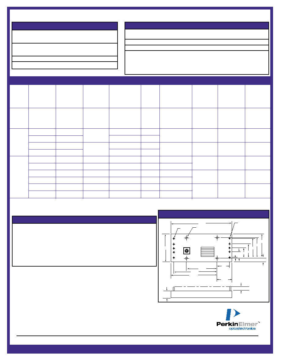
.510 ± .007
.275 ± 125
3.450
3.25
2.300
1.150
.95
2.00
+IN
ON/OFF
SYNC
PARALLEL
-IN
CUST PIN
PERKINELMER PIN
INPUT DC
DATE CODE
SERIAL NO
-V OUT
-V SENSE
V ADJ
+V SENSE
+V OUT
.05
.40
.70
1.00
1.40
1.500
1.750
.250
ÿ.080 PIN
2 PL
4.60
ÿ.156
(#6-32 INSERTS OPTIONAL)
ÿ.040 PIN
8 PL
LC810
Outline Dimensions
DS-243 Rev A 0901