www.opto.perkinelmer.com
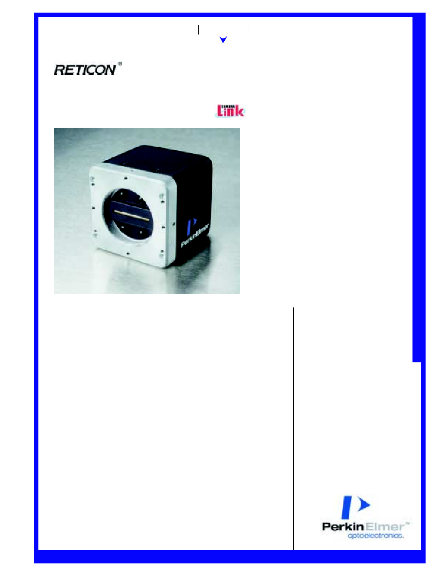
LD3500 Series
Low-Cost Digital Linescan Camera
512, 1024 and 2048 Pixels, and Parallel LVDS Outputs
Description
Features
PRELIMINAR
Y D
A
T
ASHEET
Lighting
Imaging
Telecom
Imaging Product Line
∑
20 and 40 MHz output rate models
∑
Geometrically precise 14 µm square
pixel linear CCD
∑
Small size: 2.5" H x 2.5" W x 3.2" L
∑
High dynamic range (250:1)
∑
CameraLink and Parallel LVDS
video output models
∑
8-bit grey scale resolution
∑
Antiblooming control
∑
Single power supply operation
∑
Electronic exposure control
∑
Adjustable gain levels
∑
CE mark certified
∑
Line scan rates to 68 kHz
In the LD3500-series digital linescan
camera, PerkinElmer has combined the
best features of photodiode array
detection, high-speed charge-coupled
scanning, and digital line scan camera
technology to offer an uncompromising
solution to the increasing demands of
advanced imaging applications.
The LD3500-series are high perform-
ance, low-cost, digital linescan cameras.
The LD3500 features a CameraLinkTM or
Parallel LVDS (RS-644) style video
output with resolutions of 512, 1024 or
2048 pixels, which can achieve data
rates of up to 20 or 40 MHz with excep-
tional noise immunity. The cameras are
designed for volume applications where
small size and low cost are required.
In order to allow the user to compensate
for variations in illumination found in
"real-world" application environments,
the cameras feature adjustable gain
levels. The LD3500-series cameras
feature a geometrically precise photo-
diode CCD image sensor with 14µm
photo-elements. State of the art
electronic design enables the
LD3500-series to deliver consistent,
reliable performance while the
sturdy metal housing provides
maximum protection in a variety of
harsh environment and factory floor
conditions.
The LD3500-series linescan cameras
transform light imaged during a
scene into a digital video signal.
Antiblooming structures within the
sensor ensure superior performance
over a wide range of lighting
conditions. User-defined control is
possible for line rate, integration
time and video data rate.
The LD3500 cameras may be
interfaced to most frame grabber
cards, allowing for a tested, plug and
play solution. Typical high
performance line scan applications
include lumber processing, non-
contact measurement, document
scanning, dimensional gauging,
biomedical imaging, bar code
scanning and many other industrial
and scientific applications.
PDP-206.01B - 7/2002W Page 1
www.perkinelmer.com/opto
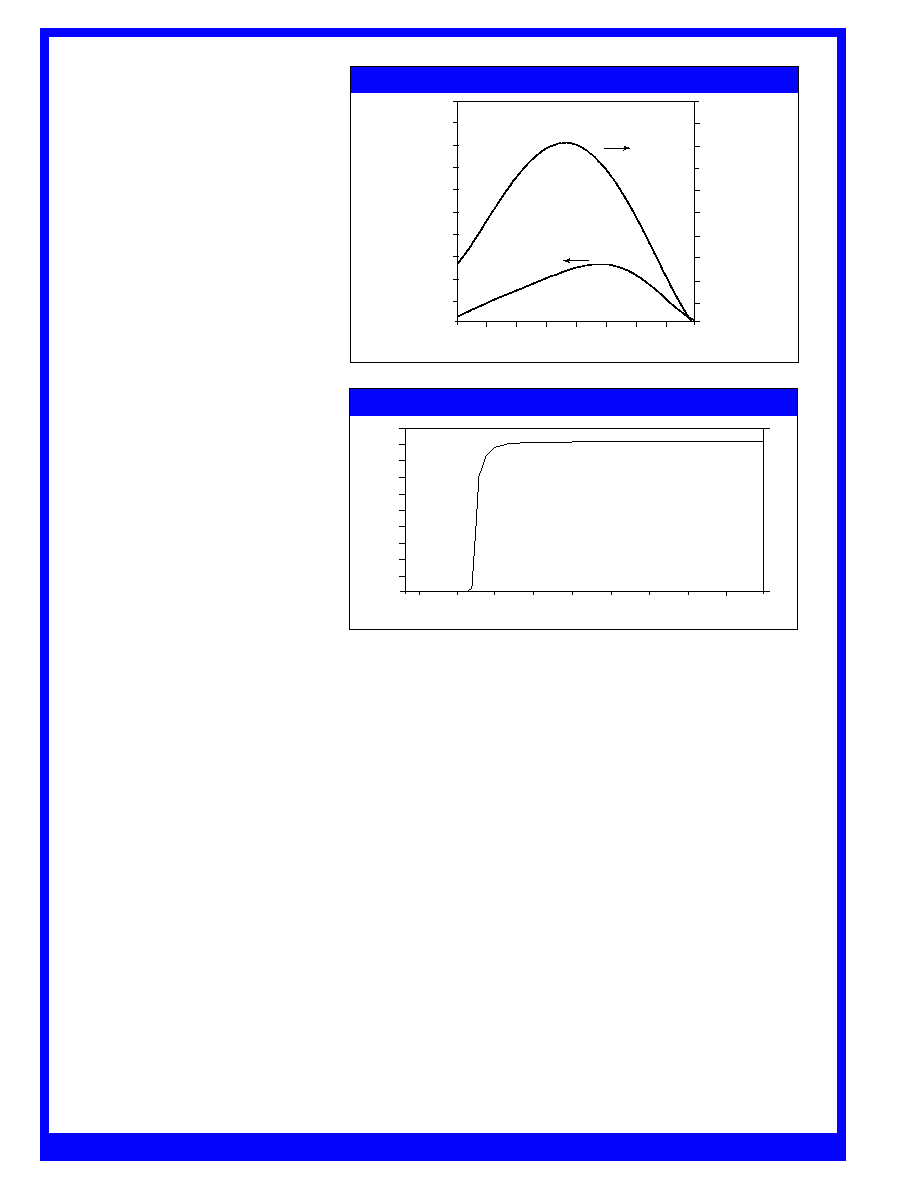
Figure1a: Spectral Sensitivity Curve (1X Gain)
100
90
80
70
60
50
40
30
20
10
0
250
350
450
550
650
750
850
950
1050
100
90
80
70
60
50
40
30
20
10
0
Wavelength (nm)
Responsivity (DN /µJ/cm )
2
QE (%)
Right Scale
Left Scale
Figure 1b: Window Transmission Curve
Wavelength (nm)
T
r
ansmission (%)
100
90
80
70
60
50
40
30
20
10
0
150
450
350
250
550
950
850
750
650
1050
Digital Linescan Camera
Sensor Description
The LD3500-series cameras contain a
single output, high-performance, high-
resolution line scan image sensor
(PerkinElmer Optoelectronics Reticon
Æ
parts RL0512PAG, RL1024PAG, or
RL2048PAG) featuring a pinned
photodiode pixel. The spectral
response of the sensor is shown in
Figure 1a, with the sensor window
transmission curve shown in Figure 1b.
Functional Description
The video signal from the sensor is
processed through a single channel of
sampled-and-held, raster order, digital
video data. The video channel signal
processing circuitry offers adjustable gain
levels that allow users to customize of
the camera to unique lighting
applications
Operating Modes
The LD3500 series cameras can operate
in Master or Slave Mode. When the
camera is set to Master Mode, the camera
operates at its maximum line scan and
data rate. When the camera is set to
Slave Mode, the cameras scan and data
rates are determined by the users input
signals to the camera. The opertaing
mode is set via the serial connection on
the CameraLink models, and is auto-
detected on the LVDS models. Auto-
detection is accomplished by looking for
either a Line Transfer (LT) and/or
External Clock signal. If the camera
receives a LT signal, but no external
clock, it will continue to run a the
maximum data rate, but will only intiate
a LT upon signal. If the camera recieves
an external clock signal, it will run at
that clock signal with either an internal
or external LT signal.
Input/Output Signal
Specifications
The LD3500 camera requires a single
DC supply (+12 to 24V) for operation.
An internal oscillator sets the default
data output rate to default model rate
(20 or 40 MHz).
CameraLink Models:
CameraLink allows for 4
manufacturer-defined camera control
signals (CC1-CC4). CC1 is a Line
Transfer (LT) signal. CC2 is a Line
Reset (LR) signal. CC3 and CC4 are
reserved for future assignment.
The rising edge of the LT signal
transfers the charge from each
photosite to the readout registers.
The readout registers, in turn,
transport the charge from each
photosite in succession to the video
outputs. The exposure time of the
camera can be externally controlled
using the LR input. The LR input is
active low (ON) in polarity and
therefore, when not in use, must be
held high or left unattended (OFF).
In this condition, the exposure time is
defined by the period of the LT signal.
Output signals are compliant with
CameraLink specifications.
Parallel LVDS (RS-644) Models:
Parallel LVDS models of the LD3500
provide Master Clock (MCLK), Line
Transfer (LT) and Line Reset (LR)
input signals. The MCLK input
determines the data rate frequency for
values up to maximum clock of the
camera. The MCLK input is optional,
as the camera is preset to run off of
the internal oscillator at the default
maximum data rate.
Should a data rate slower than that
default rate be necessary, an
externally supplied master clock can
be used. The data rate may be run
from 2 MHz to cameras maximum
clock rate. The Line Transfer input
signal transfers the charge from each
photosite to the readout registers.
The readout registers, in turn,
transport the charge from each
photosite in succession to the video
outputs.
The exposure time of a LD3500-series
camera can be controlled by using the
external LR input. The LR input is
active low (ON) in polarity and
therefore, when not in use, must be
held high or left unattended (OFF).
In this condition, the exposure time
is defined by the period of the LT
signal. When using the LR input
signal, the exposure period is defined
to be the time between the rising edge
of LT to the rising edge of LR.
The LD3500-series camera provides
two output synchronization signals:
Camera Clock (CCLK) and Line
8
PDP-206.01B - 7/2002W Page 2
Digital Linescan Camera
www.perkinelmer.com/opto
Input/Output Signal Specifications
(Continued)
Enable (LEN).
The Camera Clock (CCLK) operates at
either the MCLK frequency or default
camera frequency, and is synchronized to
the analog video. The output of the CCLK
signal can be used to capture digital video
data by a frame grabber or digitizer.
The Line Enable (LEN) signal brackets the
valid digital video. The signal becomes
high one CCLK period before the first valid
pixel and goes low one CCLK period before
the last valid pixel.
In all modes of operation on the LVDS
models, a single line delay is present due
to the necessity of storing all video data
into memory before the video is output.
Video Gain
The LD3500-series camera features an
adjustable video gain. This allows users
to amplify the video signals for individual
application needs. Photo Response Non-
Uniformity (PRNU) remains linear with
gain.
CameraLink Models:
Gain levels are set by serial
communication though the CameraLink
connector. Gain can be set from 0 to
24.5 dB in increments of 3.5 dB. Gain
settings are not lost when the camera is
powered down.
Parallel LVDS (RS-644) Models:
Gain levels are set by differential RS-644
gain control inputs on the camera
connector. The gain levels can be set at 1,
2, 4 and 8X full-scale gain, allowing the
user to easily configure the camera output
to suit their application needs. Gain
settings are not held after power down;
proper input signals must be given at
start-up, and held throughout operation
for gain settings to remain at desired
levels.
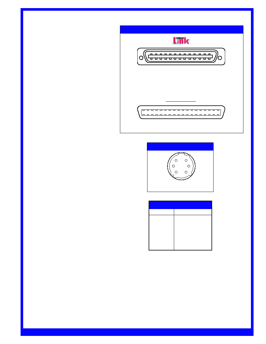
Data and Power Connectors
CameraLink Models:
The communications connector on the
LD3500-series camera is a 26-pin D-type
male connector, common to all CameraLink
applications. This 26-pin connector
contains all communications and controls
needed for camera operation. Power is
provided to the LD3500 via a 6 pin,
Hirose HR10A circular jack. Refer to Table
1a for pinout of the communications and
control connector. Figure 2 provides pinout
locations for this connector.
Figure 2. Connector Diagram
1
2
3
4
5
6
7
8
9
10
11
12
13
14
15
16
17
18
19
20
21
22
23
24
25
26
3M Connector MDR26 Position Plug
Recommended Cable: 3M14X26S2LB-XXX-OLC
1
19
18
36
Recommended Cable: 3M10136-6000EC series
Parallel LVDS
Connector: Hirose HR10A
Mating Part: Hirose HR10A-7P-6S
Figure 3. Power Connector Diagram
5
4
6
2
3
1
PDP-206.01B - 7/2002W Page 3
Pin
Signal
1
12-24VDC
2
12-24VDC
3
Do not connect
4
Do not connect
5
Ground
6
Ground
Table 2. Power Connector Pinout
Note:
The power connector and pinout are
common to all CameraLInk and Parallel
LVDS models
www.perkinelmer.com/opto
Digital Linescan Camera
www. perkinelmer.com/opto
Data and Power
Connectors (cont.)
Parallel LVDS (RS-644) Models:
The communications connector on the
LD3500 is a MDR36 (mini-D-shell)
connector. This 36 pin connector
provides all communications and
controls needed for camera operation.
Power is provided to the LD3500 via a 6
pin, Hirose HR10A circular jack.
Refer to Table 1b for pinout of the
communications and control connector.
Figure 2 provides pinout locations for
this connector
Camera Construction
The camera head is housed in a rugged,
one piece deep drawn aluminum case,
measuring 2.5" H x 2.5" W x 3.2" L
(excluding lens mounts or connector
extensions) specifically designed for
industrial applications. The sensor is
mounted on an aluminum plate that
efficiently transfers heat to the camera
case. The camera is provided with a
standard 1/4"-20 UNC tripod mounting
block, which can be attached to any of the
four sides of the camera. The mounting
holes used to attach the tripod block can
also be used to mount the camera
assembly. Additionally, the CCD sensor is
thermally coupled to the faceplate of the
camera, and the conductive cooling of this
surface is useful in minimizing thermally
generated dark current and noise of the
camera system.
PDP-206.01B - 7/2002W Page 4
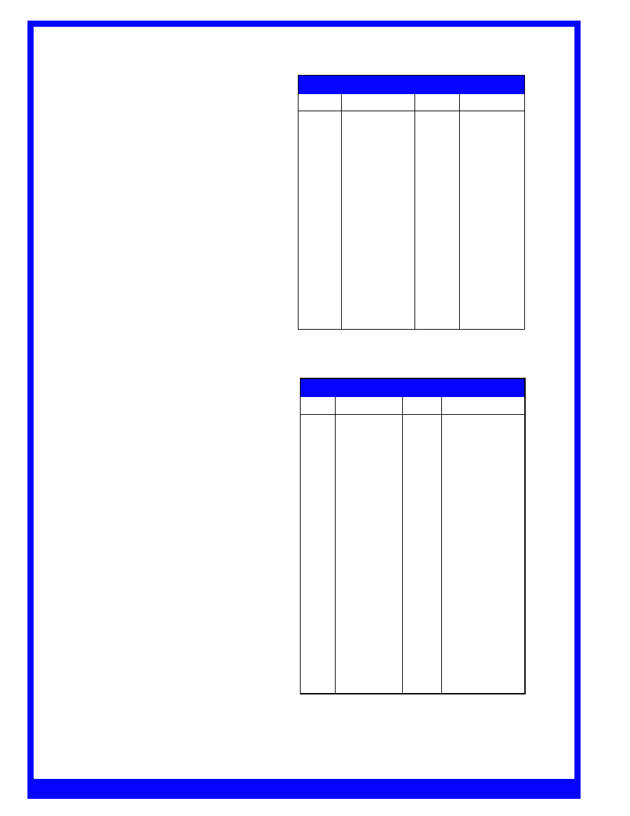
Table 1b. Parallel LVDS (RS-644) Connector Pinout
Pin
Signal
Pin
Signal
1
Do not connect
19
Do not connect
2
Gain 0+
20
Gain 0-
3
Inner Shield
21
Inner Shield
4
Gain 1+
22
Gain 1-
5
MCLK+
23
MCLK-
6
LR+
24
LR-
7
LT+
25
LT-
8
Do not connect
26
Do not connect
9
D7+
27
D7-
10
D6+
28
D6-
11
D5+
29
D5-
12
D4+
30
D4-
13
D3+
31
D3-
14
D2+
32
D2-
15
D1+
33
D1-
16
D0+
34
D0-
17
CCLK +
35
CCLK -
18
LEN+
36
LEN-
Pin
Signal
Pin
Signal
1
Inner Shield
14
Inner Shield
2
X0-
15
X0+
3
X1-
16
X1+
4
X2-
17
X2+
5
Xclk-
18
Xclk+
6
X3-
19
X3+
7
SerTC+
20
SerTC-
8
SerTFG-
21
SerTFG+
9
CC1-
22
CC1+
10
CC2+
23
CC2-
11
CC3-
24
CC3+
12
CC4+
25
CC4-
13
Inner Shield
26
Inner Shield
Table 1a. Camera Link Connector Pinout
Optical Interface
The LD3500-series cameras are equipped
with a U-Mount lens interface (MA2-1-
6H) that is aligned to the CCD sensor.
These standard adapters allow the user to
select the optimum lens to suit their
particular application.
www.perkinelmer.com/opto
Digital Linescan Camera
www.perkinelmer.com/opto
PDP-206.01B - 7/2002W Page 5
1
2
3
4
5
6
7
8
9
10
11
12
13
14
15
16
17
18
19
20
21
22
23
24
25
26
1
19
18
36
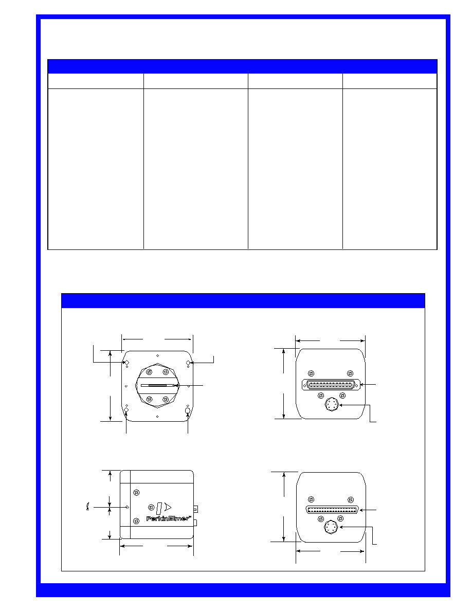
Registration Slot
0.126 x 0.09 deep x 0.150 long
2.50
(63.50)
Measurements in inches (Millimeters)
Front View
Registration Hole
0.156 x 0.09 deep
2.50
(63.50)
Registration Hole
0.126 x 0.09 deep
Pixel 1
Figure 4. Outline Drawings
Side View
1.25
(31.75)
1.25
(31.25)
3.20
(31.28)
2.50
(63.50)
CameraLink
Connector
MDR26
Power
Connector
HR10A
Rear View
CameraLink
Rear View
Parallel LVDS
MDR36
Connector
Power
Connector
HR10A
2.50
(63.50)
2.50
(63.50)
2.50
(63.50)
+002
-000
+002
-000
+002
-000
Registration Hole
0.156 x 0.09 deep
+002
-000
Table 3. LD3500 Camera Specifications
Camera Characteristics
Value
Number of Active Pixels
512, 1024, or 2048
Pixel Size
14µm x 14µm
Spectral Response
250-1000 nm
Sensor Window
Glass
Exposure Control
Yes
Antiblooming
Yes
Camera Operation Features
Number of Outputs
1
Communications Protocol
CameraLink (LD35xxPGK-011)
Parallel LVDS (LD35xxPGL-011)
Output Depth
8 bit
Adjustable Gain Range
0 to 24.5 dB (LD35xxPGK-011)
1, 2, 4, 8X (LD352xPGL-011)
PRNU
+/-10%
Dynamic Range
250:1
Maximum Output Rate
20 MHz (LD352xPGx-011)
40 MHz (LD354xPGK-011)
Lens Mount
U Mount
Temperature Requirements
Operating Temperature
-20 to 55 C
Storage Temperature
-40 to 80 C
Power Requirements
Input voltage
12 to 24 VDC
Camera Characteristics
Value