 | –≠–ª–µ–∫—Ç—Ä–æ–Ω–Ω—ã–π –∫–æ–º–ø–æ–Ω–µ–Ω—Ç: LS-5001 | –°–∫–∞—á–∞—Ç—å:  PDF PDF  ZIP ZIP |
D
A
T
ASHEET
www.perkinelmer.com/opto
.
Description
Thyratrons are fast acting high
voltage switches suitable for a
variety of applications including
radar, laser and scientific use.
PerkinElmer's thyratrons are
constructed of ceramic and
metal for strength and long life.
Over 300 thyratron types are
available from PerkinElmer. The
types listed in this guide are a
cross section of the broad line
available. We encourage
inquiries for thyratrons to suit
your particular application.
Features
∑
Wide operating voltage range
∑
High pulse rate capability
∑
Ceramic-metal construction
∑
High current capability
∑
Long life
Thyratrons
Lighting
Imaging
Telecom
High Energy Switches
How a Thyratron works
The operation of the device can
be divided into three phases: trig-
gering and commutation (closure),
steady-state conduction, and
recovery (opening), each of which
is discussed below.
Triggering and Commutation
When a suitable positive trigger-
ing pulse of energy is applied to
the grid, a plasma forms in the
grid-cathode region from elec-
trons. This plasma passes through
the apertures of the grid structure
and causes electrical breakdown
in the high-voltage region
between the grid and the anode.
This begins the process of thyra-
tron switching (also called com-
mutation). The plasma that is
formed between the grid and the
anode diffuses back through the
grid into the grid-cathode space.
"Connection" of the plasma in the
anode-grid space with the plasma
in the cathode-grid space com-
pletes the commutation process.
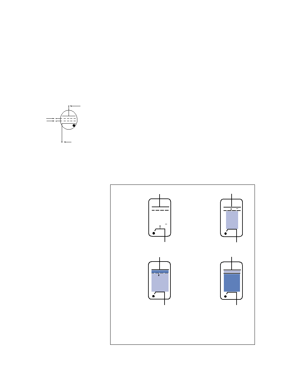
The commutation process is sim-
ply modeled as shown in Figure 2.
The time interval between trigger
breakdown of the grid-cathode
region and complete closure of
the thyratron is called the anode
delay time. It is typically 100-200
nanoseconds for most tube types.
During commutation, a high volt-
age spike appears at the grid of
the thyratron. This spike happens
in the time it takes for the plasma
in the grid-anode space to "con-
nect" to the plasma in the grid-
cathode space. During this time,
the anode is momentarily "con-
nected" to the grid thereby caus-
ing the grid to assume a voltage
nearly that of the anode's.
Although the grid spike voltage is
brief in duration, usually less than
100 nS, it can damage the grid
driver circuit unless measures
are taken to suppress the spike
before it enters the grid driver cir-
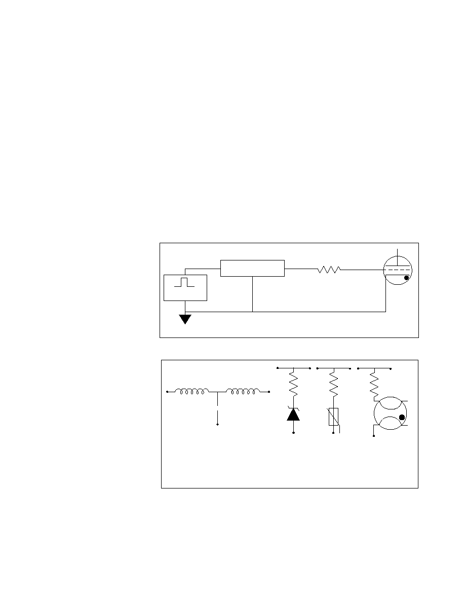
cuit. The location of the grid spike
suppression circuit is shown in
Figure 3, Grid Circuit.
Figure 4, Typical Grid Spike
Suppression Circuits, shows the
more common methods used to
protect the grid driver circuit. In
using any of these types of cir-
cuits, care must be exercised to
assure that the Grid Driver Circuit
pulse is not attenuated in an unac-
ceptable manner. The values for
the circuit components are
dependent on the characteristics
of the thyratron being driven, the
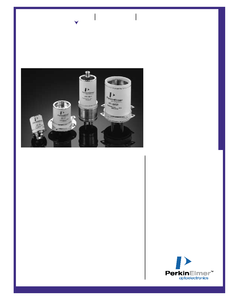
ANODE
CONTROL GRID (G2)
AUXILIARY GRID (G1)
CATHODE
Figure 1. Thyratron with auxiliary grid
(heater detail not shown)
e
e
1. Trigger pulse applied
to control grid.
2. Grid-cathode breakdown.
3. Electrons from grid-cathode
region create a dense plasma
in the grid-anode region. The
plasma front propagates to-
ward the cathode via break-
down of gas.
4. Closure
Figure 2. Thyratron commutation
Propagating
Plasma Front
grid driver circuit design, and the
performance required from the
thyratron itself. Contact the appli-
cations engineering department at
PerkinElmer to discuss the spe-
cific details of your requirement.
Conduction
Once the commutation interval
has ended, a typical hydrogen
thyratron will conduct with near-
ly constant voltage drop on the
order of 100 volts regardless of
the current through the tube.
Recovery
Thyratrons open (recover) via
diffusion of ions to the tube inner
walls and electrode surfaces,
where the ions can recombine
with electrons. This process takes
from 30 to 150 microseconds,
depending on the tube type, fill
pressure, and gas (hydrogen or
deuterium). The theoretical maxi-
mum pulse repetition rate is the
inverse of the recovery time.
Recovery can be promoted by
arranging to have a small nega-
tive DC bias voltage on the con-
trol grid when forward conduc-
tion has ceased. A bias voltage of
50 to 100 volts is usually suffi-
cient.
Recovery can also be improved
by arranging to have small nega-
tive voltage on the anode after
forward conduction has ceased.
In many radar circuits, a few-per-
cent negative mismatch between
a pulse-forming network and the
load ensures a residual negative
anode voltage. In laser circuits,
classical pulse-forming networks
are seldom used, so inverse
anode voltage may not be easily
generated. Recovery then strong-
ly depends on the characteristics
of the anode charging circuit. In
general, charging schemes
involving gently rising voltages
(i.e., resonant charging and ramp
charging) favor thyratron recov-
ery, and therefore allow higher
pulse repetition rates. Fast ramp-
ing and resistive charging put
large voltages on the anode
quickly, thus making recovery
more difficult. The ideal charging
scheme from the viewpoint of
thyratron recovery is command
charging, wherein voltage is
applied to the thyratron only an
instant before firing.
(a)
Filter
(b)
Zener
(c)
MOV
(d)
Spark Gap
Figure 4. Typical Grid Spike Suppression Circuits
CURRENT LIMITING AND/OR
MATCHING RESISTOR
Figure 3. Grid Circuit
GRID SPIKE
SUPPRESSION CIRCUIT
GRID DRIVER
CIRCUIT

Thyratrons
Type
HY-2
HY-6
HY-60
HY-61
HY-10
HY-11
HY-1A
HY-1102
HY-3192
HY-32
HY-3204
1802
HY-3002
HY-3003
HY-3004
HY-3005
HY-3025
HY-3189
HY-5
HY-53
LS-3101S
LS-4101
LS-4111
HY-3246
LS-3229
HY-3202
LS-5001
LS-5002
LS-5101
LS-5111
Peak
Anode
Voltage
epy (kV)
8
16
16
16
20
18
18
18
32
32
32
25
25
35
25
35
28
32
40
40
35
40
40
45
70
32
40
50
40
40
Peak
Anode
Current
ib (a)
100
350
350
350
500
1600
500
1000
1000
1500
1500
5000
5000
5000
5000
5000
5000
5000
5000
5000
5000
12000
12000
15000
15000
20000
20000
20000
20000
20000
Average
Anode
Current
lb (Adc)
0.1
0.5
0.5
0.5
0.5
0.5
0.5
0.5
2.2
2.2
1
2.2
2.2
2.2
2.2
2.2
2.2
2.2
8
4
2
3
3
2
2
0.5
4
4
4
4
RMS
Anode
Current
lp (Aac)
2
6.5
6.5
6.5
8
8
8
16
47.5
47.5
25
47.5
47.5
47.5
47.5
47.5
47.5
47.5
125
90
45
55
55
45
45
47.5
90
70
90
90
Plate
Dissipa-
tion
Factor
Pb
(x 109)
2.7
5
5
5
10
10
10
10
50
50
40
50
50
50
50
50
50
50
160
100
50
50
100
50
50
50
100
100
100
200
Cathode
Heater
V/A
6.3/3.5
6.3/7
6.3/7
6.3/8.5
6.3/7.5
6.3/7.5
6.3/11
6.3/7.5
6.3/12.5
6.3/18
6.3/18
6.3/12.5
6.3/12.5
6.3/12.5
6.3/12.5
6.3/12.5
6.3/12.5
6.3/12.5
6.3/30
6.3/30
6.3/18
6.3/28
6.3/28
6.3/16
6.3/16
6.3/18
6.3/29
6.3/35
6.3/29
6.3/29
Reser-
voir
Heater
V/A
Note 1
6.3/2.5
6.3/7
Note 1
6.3/4
6.3/4
Note 1
6.3/8
6.3/5.5
6.3/5.5
6.3/6
6.3/5.5
6.3/5.5
6.3/5.5
6.3/5.5
6.3/5.5
6.3/5.5
6.3/5.5
4.5/11
4.5/11
6.3/6
6.3/6
6.3/6
6.3/6
6.3/6
6.3/13
4.5/10
4.5/15
4.5/10
4.5/10
Peak
Forward
Grid
Voltage
egy
(Min)
175
150
150
150
200
200
175
20
1500
450
450
500
500
500
500
500
500
500
1300
1300
500
500
500
500
450
500
2500
2500
2500
2500
Impe-
dence
of Grid
Circuits
g (Max)
1200
1500
1500
1500
500
500
500
500
250
400
400
400
400
400
400
400
250
250
100
100
250
250
250
250
400
250
50
100
50
50
EIA Type & Comments
JAN 7621
JAN 7782
JAN 7665A
JAN 7620
JAN8613
ib to 10kA @ <1usec
JAN 7322
8614
Two gap tetrode
Two gap tetrode
Notes
1
1
1
2
3
4
4
4
3
3
6
3,6
3.5,6
3,6
2,6
3
3
3,6
3,5,6
Seated
Height x
Tube Width
(Inches)
2.35 x 1.0
2 x 1.4
2.4 x 1.4
3.6 x 1.4
3.4 x 2
2.2 x 2.25
5 x 2
2 x 2
3.75 x 3.25
4 x 3.25
3 x 6
4 x 3.25
4 x 3.25
4 x 3.25
4.75 x 3.25
4.75 x 3.25
4.25 x 3.25
3.75 x 3
5 x 4.5
5 x 4.5
5.25 x 3
8 x 3.5
8.25 x 3.5
5.75 x 3
6.4 x 3
6.4 x 3
6.75 x 4.5
9.5 x 4.5
6.75 x 4.5
7.2 x 4.5
1. Cathode and reservoir heater internally connected
2. Grounded grid design
3. Auxiliary grid design
4. MT-4 mount required
5. Liquid cooling design
6. Hollow anode design for reverse current
PerkinElmer thyratron control grid driver TM-27 recommended for use with all thyratrons up to 3 inch diameter. TM-29 recommended for thyratrons greater than 3 inch diameter.
The selections above are a representative sample of hundreds of design variations available. Contact PerkinElmer for support for any specific application.
Notes

Definition of Terms
TERMS USED TO CHARACTERIZE INDIVIDUAL PULSES
Peak Anode Voltage (epy):
maximum positive anode voltage, with respect to the cathode.
Peak Inverse Anode Voltage (epx):
maximum negative anode voltage, with respect to the cathode.
Peak Forward Anode Current (ib):
maximum instantaneous positive anode current.
Peak Inverse Current (Ibx):
maximum instantaneous negative anode current.
Pulse Width (tp):
current pulse full-width at half-maximum.
Pulse Repetition Rate (prr):
average number of pulses/second.
Current Rise Time (tr):
time for the forward current to rise from 10% to 90% of its peak value.
Anode Fall Time:
time for the forward anode voltage to collapse from 90% to 10% of its maximum value.
Anode Delay Time (tad):
time interval between triggering and commutation (commutation is defined below). The precise
reference points for this interval vary with the application.
Anode Delay Time Drift (
tad):
gradual decrease in anode delay time that occurs as the thyratron warms up.
Jitter (tj):
pulse-to-pulse variation in anode delay time.
TIME AVERAGED QUANTITIES
DC Average Current (Ib):
forward current averaged over one second.
RMS Average Current (Ip):
root-mean-square current averaged over one second.
Plate Breakdown Factor (Pb):
numerical factor proportional to the power dissipated at the anode, averaged over one
second. Pb = epy x ib x prr.
STRUCTURAL PARTS OF THE THYRATRON
Auxiliary Grid:
grid placed between the control grid and cathode in some thyratrons. A small DC current (or a larger pulsed
current) applied between Auxiliary Grid and cathode can be used to control the anode delay time. (Anode delay time is
defined above). Thyratrons with auxiliary girds are called Tetrode Thyratrons.
Reservoir:
maintains the gas pressure in the tube at a level which depends on the reservoir heater voltage.
GENERAL TERMINOLOGY
Static (Self) Breakdown Voltage (SBV):
applied voltage at which a thyratron will break down spontaneously, without
being triggered.
Commutation:
transition from trigger breakdown to full closure of the thyratron.
Recovery Time:
time which must elapse after decay of the circuit current before anode voltage can be reapplied to the
thyratron without causing self-breakdown. The maximum possible pulse repetition rate is the inverse of the recovery time.
Grid Bias:
negative DC voltage which may be applied to the control grid to speed up recovery.