1996 Mar 20
2
Philips Semiconductors
Product specification
Voltage reference diodes
1N821 to 1N829
1N821A to 1N829A
FEATURES
∑
Temperature compensated
∑
Reference voltage range:
5.89 to 6.51 V (typ. 6.20 V)
∑
Low temperature coefficient range:
max. 0.0005 to 0.01 %/K.
APPLICATION
∑
Voltage reference sources in
measuring instruments such as
digital voltmeters.
DESCRIPTION
Voltage reference diode in a hermetically-sealed SOD68 (DO-34) glass
package.
Fig.1 Simplified outline (SOD68; DO-34) and symbol.
handbook, halfpage
MAM216
k
a
LIMITING VALUES
In accordance with the Absolute Maximum Rating System (IEC 134).
SYMBOL
PARAMETER
CONDITIONS
MIN.
MAX.
UNIT
I
Z
working current
-
50
mA
P
tot
total power dissipation
T
amb
= 50
∞
C
-
400
mW
T
stg
storage temperature
-
65
+200
∞
C
T
j
junction temperature
-
200
∞
C
T
amb
operating ambient temperature
-
55
+100
∞
C
1996 Mar 20
3
Philips Semiconductors
Product specification
Voltage reference diodes
1N821 to 1N829
1N821A to 1N829A
ELECTRICAL CHARACTERISTICS
T
j
= 25
∞
C unless otherwise specified.
Notes
1. The quoted values of
V
ref
are based on a constant current I
Z
. Two factors can cause
V
ref
to change, namely the
differential resistance r
dif
and the temperature coefficient S
Z
.
a) As the max. r
dif
of the device can be 15
, a change of 0.01 mA in the current through the reference diode will
result in a
V
ref
of 0.01 mA
◊
15
= 0.15 mV. This level of
V
ref
is not significant on a 1N821 (
V
ref
< 96 mV),
it is however very significant on a 1N829 (
V
ref
< 5 mV).
b) The temperature coefficient of the reference voltage S
Z
is a function of I
Z
. Reference diodes are classified at the
specified test current and the S
Z
of the reference diode will be different at different levels of I
Z
. The absolute value
of I
Z
is important, however, the stability of I
Z
, once the level has been set, is far more significant. This applies
particularly to the 1N829. The effect of the stability of I
Z
on S
Z
is shown in Fig.3.
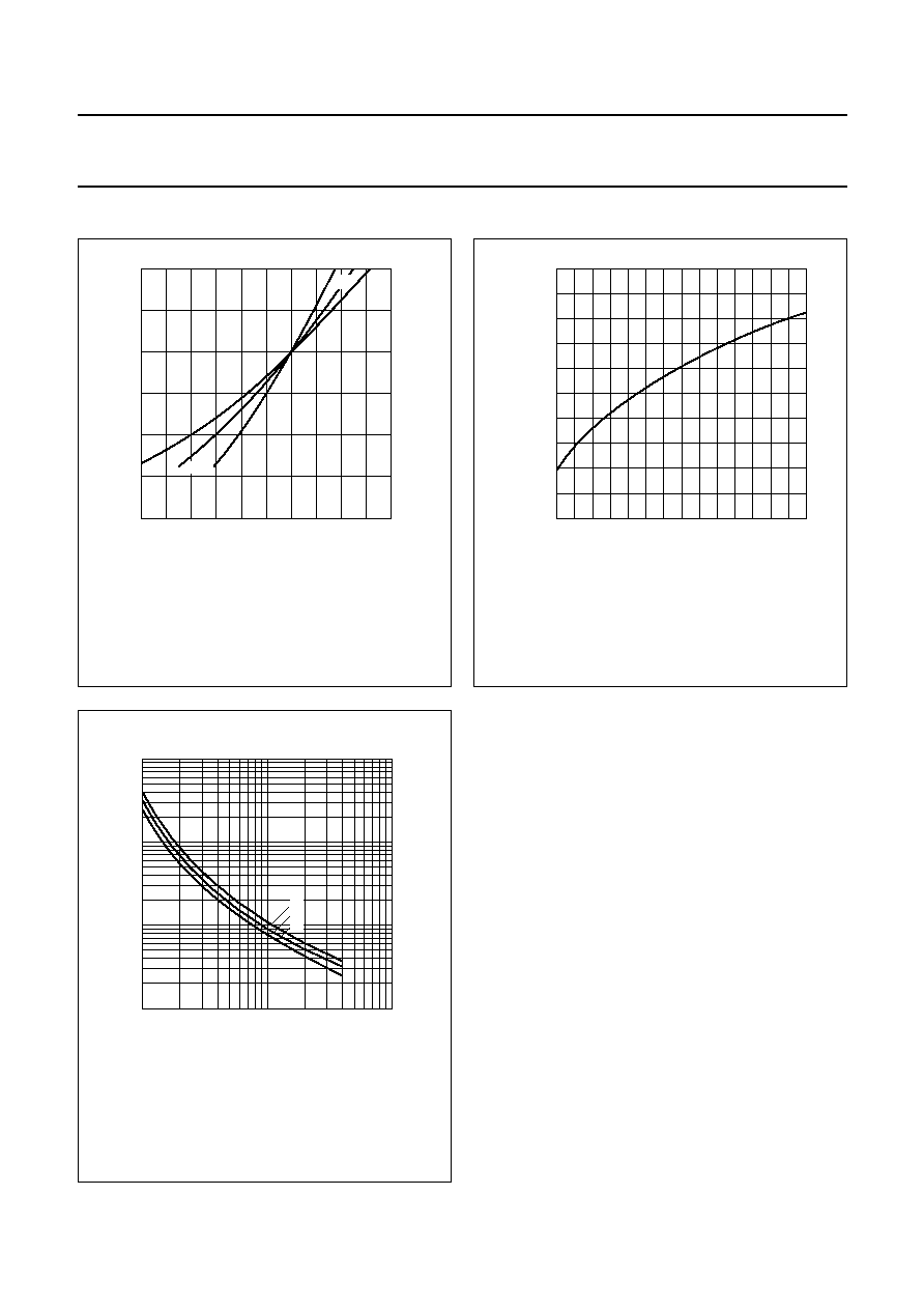
2. All reference diodes are characterized by the `box method'. This guarantees a maximum voltage excursion (
V
ref
)
over the specified temperature range, at the specified test current (I
Z
), verified by tests at indicated temperature
points within the range. V
Z
is measured and recorded at each temperature specified. The
V
ref
between the highest
and lowest values must not exceed the maximum
V
ref
given. Therefore the temperature coefficient is only given as
a reference. It may be derived from:
THERMAL CHARACTERISTICS
SYMBOL
PARAMETER
CONDITIONS
MIN.
TYP.
MAX.
UNIT
V
ref
reference voltage
I
Z
=7.5 mA
5.89
6.20
6.51
V
V
ref
reference voltage excursion
I
Z
=7.5 mA; test points for
T
amb
:
-
55; +25; +75; +100
∞
C;
see Fig.2; notes 1 and 2
1N821; 1N821A
-
-
96
mV
1N823; 1N823A
-
-
48
mV
1N825; 1N825A
-
-
19
mV
1N827; 1N827A
-
-
9
mV
1N829; 1N829A
-
-
5
mV
S
Z
temperature coefficient
I
Z
= 7.5 mA: see Fig.3;
notes 1 and 2
1N821; 1N821A
-
-
0.01
%/K
1N823; 1N823A
-
-
0.005
%/K
1N825; 1N825A
-
-
0.002
%/K
1N827; 1N827A
-
-
0.001
%/K
1N829; 1N829A
-
-
0.0005 %/K
r
dif
differential resistance
I
Z
= 7.5 mA; see Fig.4
1N821 to 1N829
-
-
15
1N821A to 1N829A
-
-
10
SYMBOL
PARAMETER
CONDITIONS
VALUE
UNIT
R
th j-tp
thermal resistance from junction to tie-point
8 mm from the body
300
K/W
R
th j-a
thermal resistance from junction to ambient
lead length 10 mm
375
K/W
S
Z
V
ref1
V
ref2
≠
T
amb2
T
amb1
≠
--------------------------------------
100
V
ref nom
-------------------- %/K
◊
=
1996 Mar 20
5
Philips Semiconductors
Product specification
Voltage reference diodes
1N821 to 1N829
1N821A to 1N829A
PACKAGE OUTLINE
DEFINITIONS
LIFE SUPPORT APPLICATIONS
These products are not designed for use in life support appliances, devices, or systems where malfunction of these
products can reasonably be expected to result in personal injury. Philips customers using or selling these products for
use in such applications do so at their own risk and agree to fully indemnify Philips for any damages resulting from such
improper use or sale.
Data Sheet Status
Objective specification
This data sheet contains target or goal specifications for product development.
Preliminary specification
This data sheet contains preliminary data; supplementary data may be published later.
Product specification
This data sheet contains final product specifications.
Limiting values
Limiting values given are in accordance with the Absolute Maximum Rating System (IEC 134). Stress above one or
more of the limiting values may cause permanent damage to the device. These are stress ratings only and operation
of the device at these or at any other conditions above those given in the Characteristics sections of the specification
is not implied. Exposure to limiting values for extended periods may affect device reliability.
Application information
Where application information is given, it is advisory and does not form part of the specification.
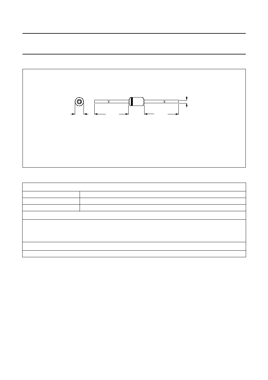
Fig.5 SOD68 (DO-34).
Dimensions in mm.
The marking band indicates the cathode.
The diodes are type branded.
handbook, full pagewidth
1.6
max
25.4 min
25.4 min
3.04
max
0.55
max
MSA212 - 1