 | ÐлекÑÑоннÑй компоненÑ: 74HC4059D | СкаÑаÑÑ:  PDF PDF  ZIP ZIP |
Äîêóìåíòàöèÿ è îïèñàíèÿ www.docs.chipfind.ru
DATA SHEET
Product specification
Supersedes data of September 1993
File under Integrated Circuits, IC06
1998 Jul 08
INTEGRATED CIRCUITS
74HC/HCT4059
Programmable divide-by-n counter
For a complete data sheet, please also download:
·
The IC06 74HC/HCT/HCU/HCMOS Logic Family Specifications
·
The IC06 74HC/HCT/HCU/HCMOS Logic Package Information
·
The IC06 74HC/HCT/HCU/HCMOS Logic Package Outlines

1998 Jul 08
2
Philips Semiconductors
Product specification
Programmable divide-by-n counter
74HC/HCT4059
FEATURES
·
Synchronous programmable divide-by-n counter
·
Presettable down counter
·
Fully static operation
·
Mode select control of initial decade counting function
(divide-by-10, 8, 5, 4 and 2)
·
Master preset initialization
·
Latchable output
·
Easily cascadable with other counters
·
Four operating modes:
timer
divider-by-n
divide-by-10 000
master preset
·
Output capability: standard
·
I
CC
category: MSI
GENERAL DESCRIPTION
The 74HC/HCT4059 are high-speed Si-gate CMOS
devices and are pin compatible with the "4059" of the
"4000B" series. They are specified in compliance with
JEDEC standard no. 7A.
The 74HC/HCT4059 are divide-by-n counters which can
be programmed to divide an input frequency by any
number (n) from 3 to 15 999. There are four operating
modes, timer, divide-by-n, divide-by-10 000 and master
preset, which are defined by the mode select inputs (K
a
to
K
c
) and the latch enable input (LE) as shown in the
Function table.
The complete counter consists of a first counting stage, an
intermediate counting stage and a fifth counting stage. The
first counter stage consists of four independent flip-flops.
Depending on the divide-by-mode, at least one flip-flop is
placed at the input of the intermediate stage (the remaining
flip-flops are placed at the fifth stage with a place value of
thousands). The intermediate stage consists of three
cascaded decade counters, each containing four flip-flops.
All flip-flops can be preset to a desired state by means of
the JAM inputs (J
1
to J
16
), during which the clock input
(CP) will cause all stages to count from n to zero. The
zero-detect circuit will then cause all stages to return to the
JAM count, during which an output pulse is generated. In
the timer mode, after an output pulse is generated, the
output pulse remains HIGH until the latch input (LE) goes
LOW. The counter will advance, even if LE is HIGH and
the output is latched in the HIGH state.
In the divide-by-n mode, a clock cycle wide pulse is
generated with a frequency rate equal to the input
frequency divided by n.
The function of the mode select and JAM inputs are
illustrated in the following examples. In the divide-by-2
mode, only one flip-flop is needed in the first counting
section. Therefore the last (5th) counting section has three
flip-flops that can be preset to a maximum count of seven
with a place value of thousands. This counting mode is
selected when K
a
to K
c
are set HIGH. In this case input J
1
is used to preset the first counting section and J
2
to J
4
are
used to preset the last (5th) counting section.
If the divide-by-10 mode is desired for the first section, K
a
and K
b
are set HIGH and K
c
is set LOW. The JAM inputs
J
1
to J
4
are used to preset the first counting section (there
is no last counting section). The intermediate counting
section consists of three cascaded BCD decade
(divide-by-10) counters, presettable by means of the JAM
inputs J
5
to J
16
.
The preset of the counter to a desired divide-by-n is
achieved as follows:
n = (MODE
(1)
) (1 000 x decade 5 preset
+
100 x decade 4 preset
+
10 x decade 3 preset
+
1 x decade 2 preset)
+
decade 1 preset
To calculate preset values for any "n" count, divide the "n"
count by the selected mode. The resultant is the
corresponding preset value of the 5th to the 2nd decade
with the remainder being equal to the 1st decade value;
preset value = n/mode.
If n = 8 479, and the selected mode = 5, the preset
value = 8 479/5 = 1 695 with a remainder of 4, thus the
JAM inputs must be set as shown in Table 1.
To verify the results, use the given equation:
n = 5 (1 000
×
1
+
100
×
6
+
10
×
9
+
1
×
5)
+
4
n = 8 479.
If n = 12 382 and the selected mode = 8, the preset
value = 12 382/8 = 1 547 with a remainder of 6, thus the
JAM inputs must be set as shown in Table 2.
To verify:
n = 8 (1 000
×
1
+
100
×
5
+
10
×
4
+
1
×
7)
+
6
n = 12 382.
(1)
MODE = first counting section divider
(10, 8, 5, 4 or 2).

1998 Jul 08
3
Philips Semiconductors
Product specification
Programmable divide-by-n counter
74HC/HCT4059
If n = 8 479 and the selected mode = 10, the preset
value = 8 479/10 with a remainder of 9, thus the JAM
inputs must be set as shown in Table 3.
To verify:
n = 10 (1 000
×
0
+
100
×
8
+
10
×
4
+
1
×
7)
+
9
n = 8 479.
The three decades of the intermediate counting section
can be preset to a binary 15 instead of a BCD 9. In this
case the first cycle of a counter consists of 15 count
pulses, the next cycles consisting of 10 counting pulses.
Thus the place value of the three decades are still 1, 10
and 100. For example, in the divide-by-8 mode, the
number from which the intermediate counting section
begins to count-down can be preset to:
3rd decade: 1 500
2nd decade:
150
1st decade:
15
The last counting section can be preset to a maximum of
1, with a place value of 1 000. The first counting section
can be preset to a maximum of 7. To calculate n:
n = 8 (1 000
×
1
+
100
×
15
+
10
×
15
+
1
×
15)
+
7
n = 21 327.
21 327 is the maximum possible count in the divide-by-8
mode. The highest count of the various modes is shown in
the Function table, in the column entitled "binary counter
range".
The mode select inputs permit, when used with decimal
programming, a non-BCD least significant digit. For
example, the channel spacing in a radio is 12.5 kHz, it may
be convenient to program the counter in decimal steps of
100 kHz subdivided into 8 steps of 12.5 kHz controlled by
the least significant digit. Also frequency synthesizer
channel separations of 10, 12.5, 20, 25 and 50 parts can
be chosen by the mode select inputs. This is called
"Fractional extension". A similar extension called "Half
channel offset" can be obtained in modes 2, 4, 6 and 8, if
the JAM inputs are switched between zero and 1, 2, 3 and
4 respectfully. This is illustrated in Fig.5.
This feature is used primarily in cases where radio
channels are allocated according to the following formula:
Channel frequency = channel spacing x (N
+
0.5)
N is an integer.
Control inputs K
b
and K
c
can be used to initiate and lock
the counter in the "master preset" mode. In this condition
the flip-flops in the counter are preset in accordance with
the JAM inputs and the counter remains in that mode as
long as K
b
and K
c
both remain LOW. The counter begins
to count down from the preset state when a counting mode
other than the "master preset" mode is selected.
Whenever the "master preset" mode is used, control
signals K
b
= K
c
= LOW must be applied for at least 2 full
clock pulses. After the "master preset" mode inputs have
been changed to one of the counting modes, the next
positive-going clock transition changes an internal flip-flop
so that the count-down begins on the second
positive-going clock transition. Thus, after a "master
preset" mode, there is always one extra count before the
output goes HIGH. Figure 6 illustrates the operation of the
counter in the divide-by-8 mode starting from the preset
state 3.
If the "master preset" mode is started two clock cycles or
less before an output pulse, the output pulse will appear at
the correct moment. When the output pulse appears and
the "master preset" mode is not selected, the counter is
preset according to the states of the JAM inputs.
When K
a
, K
b
, K
c
and LE are LOW, the counter operates in
the "preset inhibit" mode, during which the counter divides
at a fixed rate of 10 000, independent of the state of the
JAM inputs. However, the first cycle length after leaving
the "master preset" mode is determined by the JAM inputs.
When K
a
, K
b
and K
c
are LOW and input LE = HIGH, the
counter operates in the normal divide-by-10 mode,
however, without the latch operation at the output.
This device is particularly advantageous in digital
frequency synthesizer circuits (VHF, UHF, FM, AM etc.)
for communication systems, where programmable
divide-by-"n" counters are an integral part of the
synthesizer phase-locked-loop sub-system. The
74HC/HCT4059 can also be used to perform the
synthesizer "fixed divide-by-n" counting function, as well
as general purpose counting for instrumentation functions
such as totalizers, production counters and "time out"
timers.
Schmitt-trigger action at the clock input makes the circuit
highly tolerant to slower clock rise and fall times.
1998 Jul 08
4
Philips Semiconductors
Product specification
Programmable divide-by-n counter
74HC/HCT4059
QUICK REFERENCE DATA
GND = 0 V; T
amb
= 25
°
C; t
r
= t
f
= 6 ns
Notes
1. C
PD
is used to determine the dynamic power dissipation (P
D
in
µ
W):
P
D
= C
PD
×
V
CC
2
×
f
i
+
(C
L
×
V
CC
2
×
f
o
) where:
f
i
= input frequency in MHz
f
o
= output frequency in MHz
(C
L
×
V
CC
2
×
f
o
) = sum of outputs
C
L
= output load capacitance in pF
V
CC
= supply voltage in V
2. For HC the condition is V
I
= GND to V
CC
For HCT the condition is V
I
= GND to V
CC
-
1.5 V
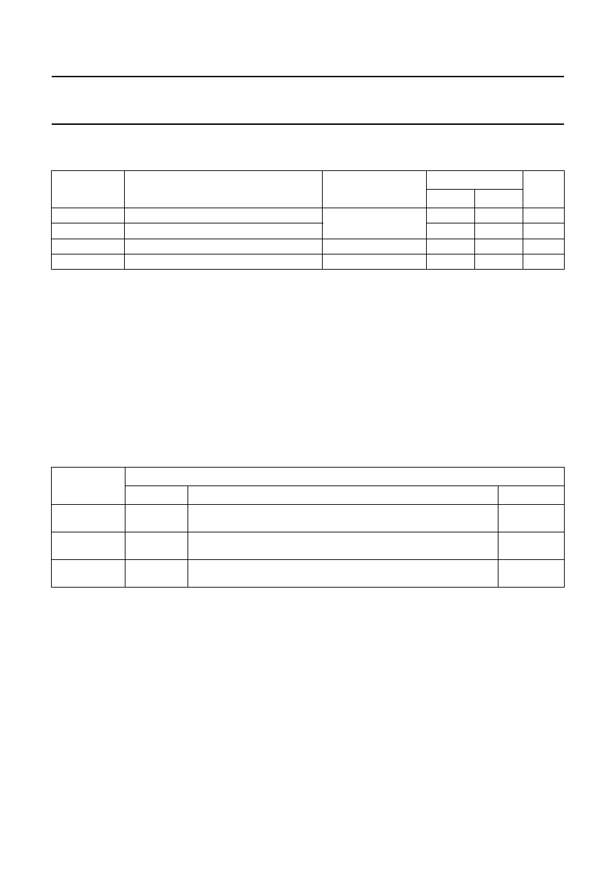
ORDERING INFORMATION
SYMBOL
PARAMETER
CONDITIONS
TYPICAL
UNIT
HC
HCT
t
PHL
/ t
PLH
propagation delay CP to Q
C
L
= 15 pF; V
CC
= 5 V 18
20
ns
f
max
maximum clock frequency
40
40
MHz
C
I
input capacitance
3.5
3.5
pF
C
PD
power dissipation capacitance per package
notes 1 and 2
30
32
pF
TYPE
NUMBER
PACKAGE
NAME
DESCRIPTION
VERSION
74HC4059N3;
74HCT4059N3
DIP24
plastic dual in-line package; 24 leads (300 mil)
SOT222-1
74HC4059N;
74HCT4059N
DIP24
plastic dual in-line package; 24 leads (600 mil)
SOT101-1
74HC4059D;
74HCT4059D
SO24
plastic small outline package; 24 leads; body width 7.5 mm
SOT137-1
1998 Jul 08
5
Philips Semiconductors
Product specification
Programmable divide-by-n counter
74HC/HCT4059
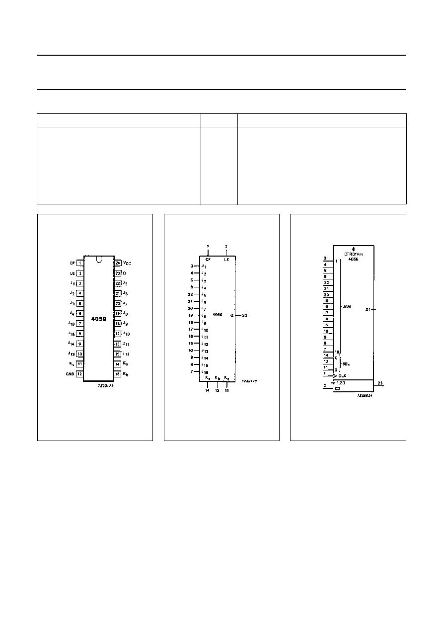
PIN DESCRIPTION
PIN NO.
SYMBOL
NAME AND FUNCTION
1
CP
clock input (LOW-to-HIGH, edge-triggered)
2
LE
latch enable (active HIGH)
3, 4, 5, 6, 22, 21, 20, 19, 18, 17, 16, 15, 10, 9, 8, 7
J
1
to J
16
programmable JAM inputs (BCD)
12
GND
ground (0 V)
14, 13, 11
K
a
to K
c
mode select inputs
23
Q
divide-by-n output
24
V
CC
positive supply voltage
Fig.1 Pin configuration.
Fig.2 Logic symbol.
Fig.3 IEC logic symbol.