2002 Mar 05
2
Philips Semiconductors
Product specification
VHF variable capacitance diode
BB157
FEATURES
∑
High linearity
∑
Excellent matching to 2% DMA
∑
Very small plastic SMD package
∑
C25: 2.75 pF; ratio: min. 11
∑
Low series resistance.
APPLICATIONS
∑
Electronic tuning in VHF television tuners
∑
Voltage controlled oscillators (VCO).
DESCRIPTION
The BB157 is a variable capacitance diode, fabricated in
planar technology and encapsulated in the SOD323
(SC-76) very small plastic SMD package. The excellent
matching performance is achieved by gliding matching
and a Direct Matching Assembly (DMA) procedure.
MARKING
PINNING
TYPE NUMBER
MARKING CODE
BB157
PG
PIN
DESCRIPTION
1
cathode
2
anode
handbook, 2 columns
1
2
MAM392
Fig.1
Simplified outline SOD323 (SC76) and
symbol.
The marking bar indicates the cathode.
LIMITING VALUES
In accordance with the Absolute Maximum Rating System (IEC 60134).
SYMBOL
PARAMETER
CONDITIONS
MIN.
MAX.
UNIT
V
R
continuous reverse voltage
-
30
V
V
RM
peak reverse voltage
in series with a 10 k
resistor
-
35
V
I
F
continuous forward current
-
20
mA
T
stg
storage temperature
-
55
+150
∞
C
T
j
operating junction temperature
-
55
+150
∞
C
2002 Mar 05
3
Philips Semiconductors
Product specification
VHF variable capacitance diode
BB157
CHARACTERISTICS
T
j
= 25
∞
C unless otherwise specified.
SYMBOL
PARAMETER
CONDITIONS
MIN.
TYP.
MAX.
UNIT
I
R
reverse current
V
R
= 30 V; see Fig.3
-
-
10
nA
V
R
= 30 V; T
j
= 85
∞
C; see Fig.3
-
-
200
nA
r
s
diode series resistance
f = 470 MHz; V
R
= 5 V
-
-
0.75
C
d
diode capacitance
V
R
= 1 V; f = 1 MHz; see Figs 2 and 4
37.5
-
43.8
pF
V
R
= 2 V; f = 1 MHz; see Figs 2 and 4
29.3
-
34.2
pF
V
R
= 25 V; f = 1 MHz; see Figs 2 and 4 2.57
-
2.92
pF
V
R
= 28 V; f = 1 MHz; see Figs 2 and 4 2.42
-
2.76
pF
capacitance ratio
f = 1 MHz
11
-
-
capacitance ratio
f = 1 MHz
14.85
-
-
capacitance matching
V
R
= 2 to 25 V; in a sequence of 15
diodes (gliding)
-
-
2
%
C
d 2V
(
)
C
d 25V
(
)
-------------------
C
d 1V
(
)
C
d 28V
(
)
-------------------
C
d
C
d
----------
2002 Mar 05
4
Philips Semiconductors
Product specification
VHF variable capacitance diode
BB157
handbook, full pagewidth
0
50
10
20
30
40
MGU594
10
-
1
1
Cd
(pF)
10
VR (V)
10
2
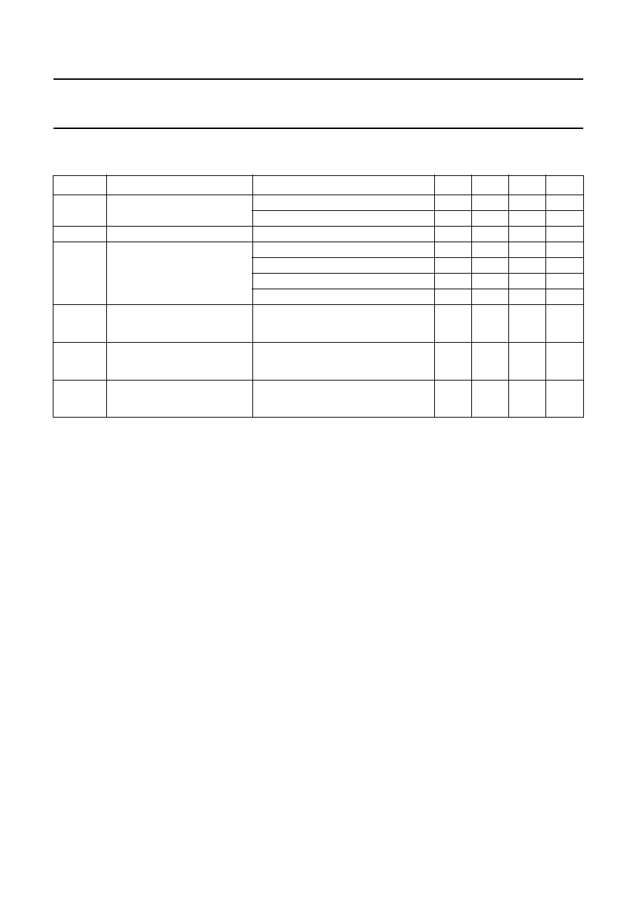
Fig.2 Diode capacitance as a function of reverse voltage; typical values.
f = 1 MHz; T
j
= 25
∞
C
.
handbook, halfpage
100
0
10
MLC816
10
2
10
3
50
IR
(nA)
T ( C)
j
o
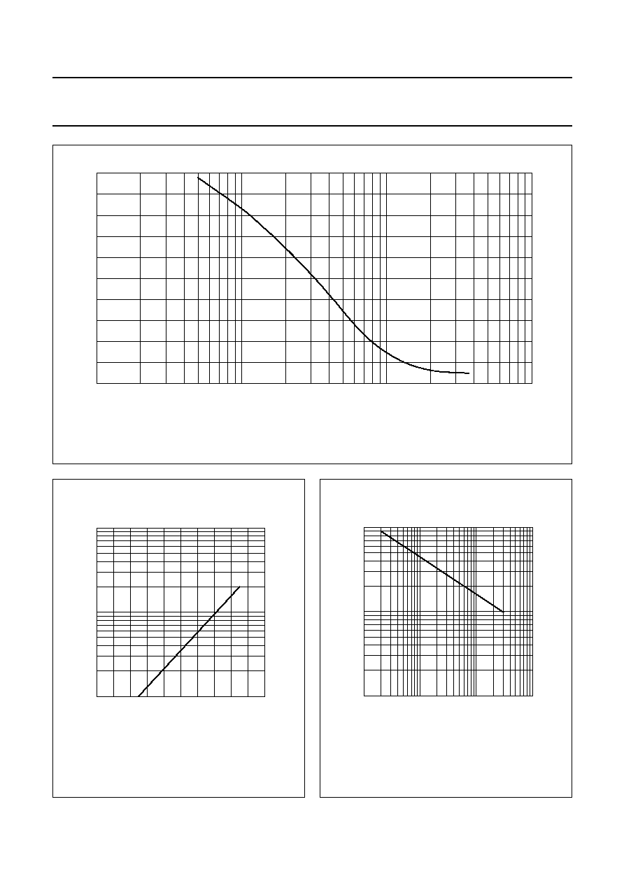
Fig.3
Reverse current as a function of junction
temperature; maximum values.
handbook, halfpage
10
-
3
10
-
4
10
-
5
MGU595
10
-
1
1
10
TCd
(K
-
1
)
VR (V)
10
2
Fig.4
Temperature coefficient of diode
capacitance as a function of reverse
voltage; typical values.

2002 Mar 05
5
Philips Semiconductors
Product specification
VHF variable capacitance diode
BB157
PACKAGE OUTLINE
REFERENCES
OUTLINE
VERSION
EUROPEAN
PROJECTION
ISSUE DATE
IEC
JEDEC
EIAJ
SOD323
SC-76
98-09-14
99-09-13
0
1
2 mm
scale
SOD323
UNIT
bp
c
D
E
Q
v
mm
0.40
0.25
+
0.05
-
0.05
0.25
0.10
0.2
1.35
1.15
1.8
1.6
A
1.1
0.8
HE
2.7
2.3
0.25
0.15
Lp
0.45
0.15
DIMENSIONS (mm are the original dimensions)
D
1
2
HE
Lp
A
E
bp
A1
Q
Note
1. The marking bar indicates the cathode.
A1
max.
Plastic surface mounted package; 2 leads
v
M
A
A
c
(1)