1.
Product profile
1.1 General description
The BB208-02 is a planar technology variable capacitance diode in a SOD523 (SC-79)
ultra small SMD plastic package.
The BB208-03 is a planar technology variable capacitance diode in a SOD323 (SC-76)
very small SMD plastic package.
1.2 Features
s
Very small SMD plastic packages
s
Very low series resistance
s
Excellent CV linearity
s
C
d(1V)
: 21.5 pF; C
d(7.5V)
: 4.9 pF
s
High ratio.
1.3 Applications
s
Voltage Controlled Oscillators (VCO)
s
Voltage Controlled Crystal Oscillators/Temperature Controlled Crystal Oscillators
(VCXO/TCXO).
2.
Pinning information
BB208-02; BB208-03
Low voltage variable capacitance diode
Rev. 01 -- 7 April 2004
Product data sheet
Table 1:
Discrete pinning: SOD523
Pin
Description
Simplified outline
Symbol
1
cathode
2
anode
Table 2:
Discrete pinning: SOD323
Pin
Description
Simplified outline
Symbol
1
cathode
2
anode
1
2
Top view
sym008
Top view
2
1
sym008

9397 750 12696
� Koninklijke Philips Electronics N.V. 2004. All rights reserved.
Product data sheet
Rev. 01 -- 7 April 2004
2 of 8
Philips Semiconductors
BB208-02; BB208-03
Low voltage variable capacitance diode
3.
Ordering information
4.
Marking
5.
Limiting values
6.
Characteristics
Table 3:
Ordering information
Type number
Package
Name
Description
Version
BB208-02
-
plastic surface mounted package; 2 leads
SOD523
BB208-03
-
plastic surface mounted package; 2 leads
SOD323
Table 4:
Marking
Type number
Marking code
BB208-02
A1
BB208-03
A2
Table 5:
Limiting values
In accordance with the Absolute Maximum Rating System (IEC 60134).
Symbol
Parameter
Conditions
Min
Max
Unit
V
R
continuous reverse voltage
-
10
V
I
F
continuous forward current
-
20
mA
T
stg
storage temperature
-
55
+150
�
C
T
j
operating junction temperature
-
55
+125
�
C
Table 6:
Electrical characteristics
T
j
= 25
�
C unless otherwise specified.
Symbol
Parameter
Conditions
Min
Typ
Max
Unit
I
R
reverse current
V
R
= 10 V; see
Figure 2
-
-
10
nA
V
R
= 10 V; T
j
= 85
�
C; see
Figure 2
-
-
200
nA
r
s
diode series resistance
f = 100 MHz; V
R
= 3 V
-
0.35
0.5
C
d
diode capacitance
f = 1 MHz; see
Figure 1
and
Figure 3
V
R
= 1 V
19.9
-
23.2
pF
V
R
= 4 V
-
10.1
-
pF
V
R
= 7.5 V
4.5
-
5.4
pF
capacitance ratio
f = 1 MHz
2.0
-
-
capacitance ratio
f = 1 MHz
3.7
-
5.2
C
d 1V
(
)
C
d 4V
(
)
----------------
C
d 1V
(
)
C
d 7.5V
(
)
--------------------
9397 750 12696
� Koninklijke Philips Electronics N.V. 2004. All rights reserved.
Product data sheet
Rev. 01 -- 7 April 2004
3 of 8
Philips Semiconductors
BB208-02; BB208-03
Low voltage variable capacitance diode
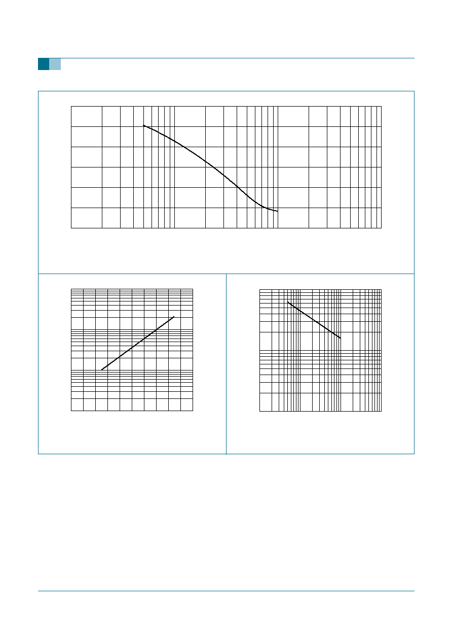
f = 1 MHz; T
j
= 25
�
C.
Fig 1.
Diode capacitance as a function of reverse voltage; typical values.
Fig 2.
Reverse current as a function of junction
temperature; typical values.
Fig 3.
Temperature coefficient of diode capacitance
as a function of reverse voltage; typical values.
001aaa524
10
20
30
C
d
(pF)
0
V
R
(V)
10
-
1
10
2
10
1
mlc816
10
2
10
10
3
I
R
(nA)
1
T
j
(
�
C)
0
100
80
40
60
20
001aaa525
V
R
(V)
10
-
1
10
2
10
1
10
-
4
10
-
3
TC
d
(K-1)
10
-
5
9397 750 12696
� Koninklijke Philips Electronics N.V. 2004. All rights reserved.
Product data sheet
Rev. 01 -- 7 April 2004
4 of 8
Philips Semiconductors
BB208-02; BB208-03
Low voltage variable capacitance diode
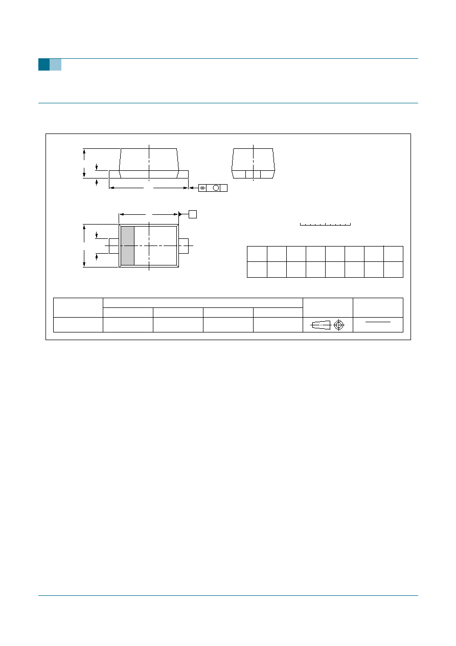
7.
Package outline
Fig 4.
Package outline (BB208-02).
REFERENCES
OUTLINE
VERSION
EUROPEAN
PROJECTION
ISSUE DATE
IEC
JEDEC
JEITA
SOD523
SC-79
98-11-25
02-12-13
Plastic surface mounted package; 2 leads
SOD523
0
0.5
1 mm
scale
D
1
2
HE
E
bp
A
c
v
M
A
A
UNIT
bp
c
D
E
v
mm
A
HE
DIMENSIONS (mm are the original dimensions)
Note
1. The marking bar indicates the cathode.
(1)
0.34
0.26
0.17
0.11
0.1
0.85
0.75
1.25
1.15
0.65
0.58
1.65
1.55
9397 750 12696
� Koninklijke Philips Electronics N.V. 2004. All rights reserved.
Product data sheet
Rev. 01 -- 7 April 2004
5 of 8
Philips Semiconductors
BB208-02; BB208-03
Low voltage variable capacitance diode
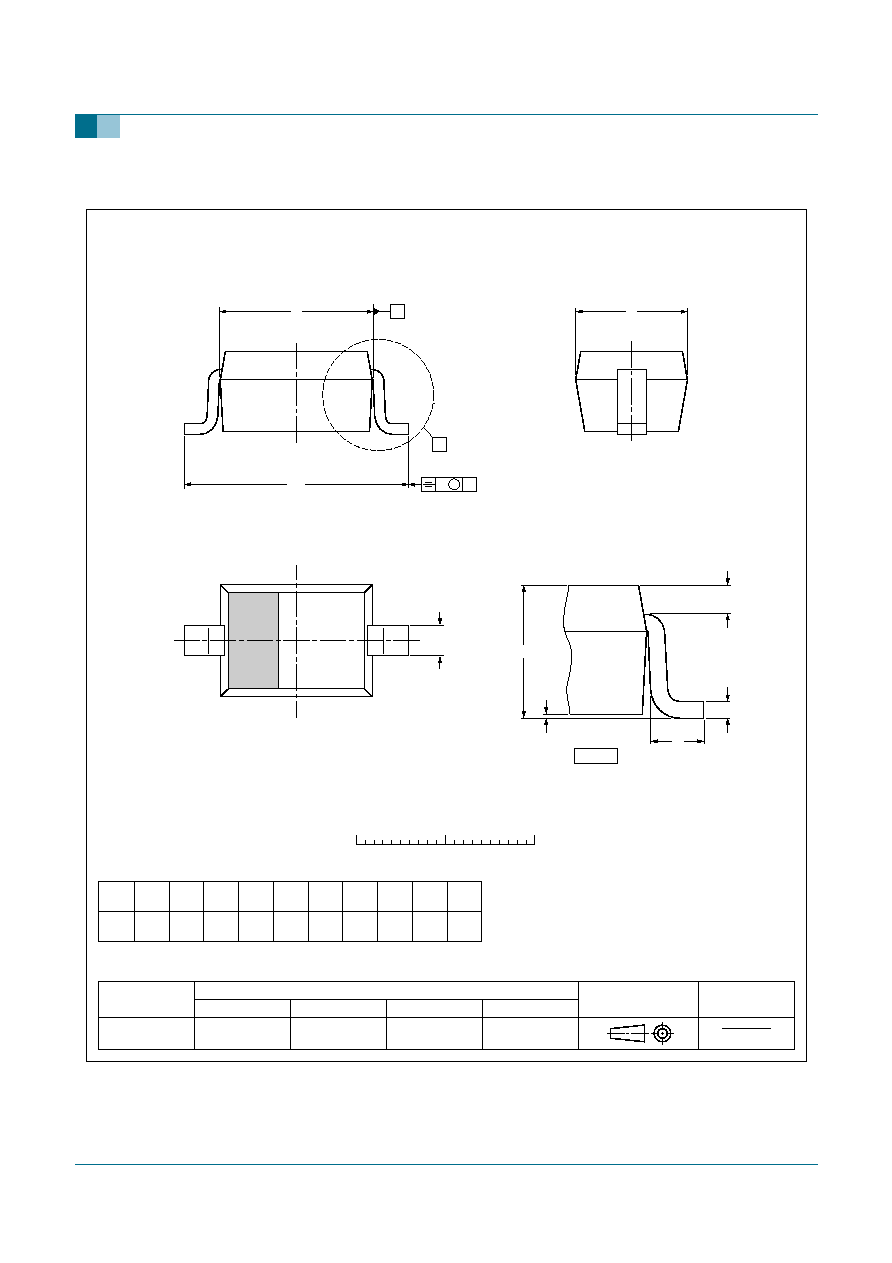
Fig 5.
Package outline (BB208-03).
REFERENCES
OUTLINE
VERSION
EUROPEAN
PROJECTION
ISSUE DATE
IEC
JEDEC
JEITA
SOD323
SC-76
SOD323
99-09-13
03-12-17
Note
1. The marking bar indicates the cathode
UNIT
A
mm
0.05
1.1
0.8
0.40
0.25
0.25
0.10
1.8
1.6
1.35
1.15
2.7
2.3
0.45
0.15
A
1
max
DIMENSIONS (mm are the original dimensions)
Plastic surface mounted package; 2 leads
0
1
(1)
2
1
2 mm
scale
b
p
c
D
E
H
D
Q
0.25
0.15
L
p
v
0.2
A
D
A
E
L
p
b
p
detail X
A
1
c
Q
H
D
v
A
M
X