 | –≠–ª–µ–∫—Ç—Ä–æ–Ω–Ω—ã–π –∫–æ–º–ø–æ–Ω–µ–Ω—Ç: BB911 | –°–∫–∞—á–∞—Ç—å:  PDF PDF  ZIP ZIP |
Document Outline
- FEATURES
- APPLICATIONS
- DESCRIPTION
- LIMITING VALUES
- ELECTRICAL CHARACTERISTICS
- GRAPHICAL DATA
- PACKAGE OUTLINE
- DEFINITIONS
- LIFE SUPPORT APPLICATIONS
DATA SHEET
Product specification
Supersedes data of December 1993
File under Discrete Semiconductors, SC01
1996 May 03
DISCRETE SEMICONDUCTORS
BB911/A
VHF variable capacitance diode
M3D051
1996 May 03
2
Philips Semiconductors
Product specification
VHF variable capacitance diode
BB911/A
FEATURES
∑
High linearity
∑
Matched to 2.5%
∑
Hermetically sealed leaded glass
SOD68 (DO-34) package
∑
C28: 2.7 pF; ratio: 25.
APPLICATIONS
∑
Electronic tuning in VHF television
tuners, band A up to 160 MHz
∑
VCO.
DESCRIPTION
The BB911/A is a variable
capacitance diode, fabricated in
planar technology, and encapsulated
in the hermetically sealed leaded
glass SOD68 (DO-34) package.
LIMITING VALUES
In accordance with the Absolute Maximum Rating System (IEC 134).
SYMBOL
PARAMETER
MIN.
MAX.
UNIT
V
R
continuous reverse voltage
-
30
V
I
F
continuous forward current
-
20
mA
T
stg
storage temperature
-
55
+150
∞
C
T
j
operating junction temperature
-
55
+100
∞
C
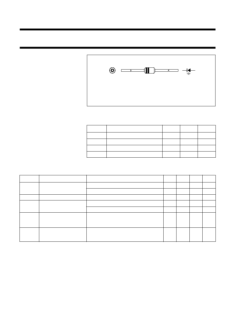
Fig.1 Simplified outline (SOD68; DO-34) and symbol.
Cathode side indicated by a red band on a black body.
Additional white band.
handbook, halfpage
MAM234
k
a
ELECTRICAL CHARACTERISTICS
T
j
= 25
∞
C; unless otherwise specified.
Note
1. V
R
is the value at which C
d
= 40 pF.
SYMBOL
PARAMETER
CONDITIONS
MIN.
TYP.
MAX.
UNIT
I
R
reverse current
V
R
= 30 V; see Fig.3
-
-
10
nA
V
R
= 30 V; T
j
= 85
∞
C; see Fig.3
-
-
200
nA
r
s
diode series resistance
f = 100 MHz; note 1
-
-
2
C
d
diode capacitance
V
R
= 0.5 V; f = 1 MHz; see Figs 2 and 4
60
-
75
pF
V
R
= 28 V; f = 1 MHz; see Figs 2 and 4
2.4
-
2.9
pF
capacitance ratio
f = 1 MHz
23.3
-
28.4
capacitance matching
V
R
= 0.5 to 28 V
-
-
2.5
%
C
d 0.5V
(
)
C
d 28V
(
)
----------------------
C
d
C
d
----------
1996 May 03
3
Philips Semiconductors
Product specification
VHF variable capacitance diode
BB911/A
GRAPHICAL DATA
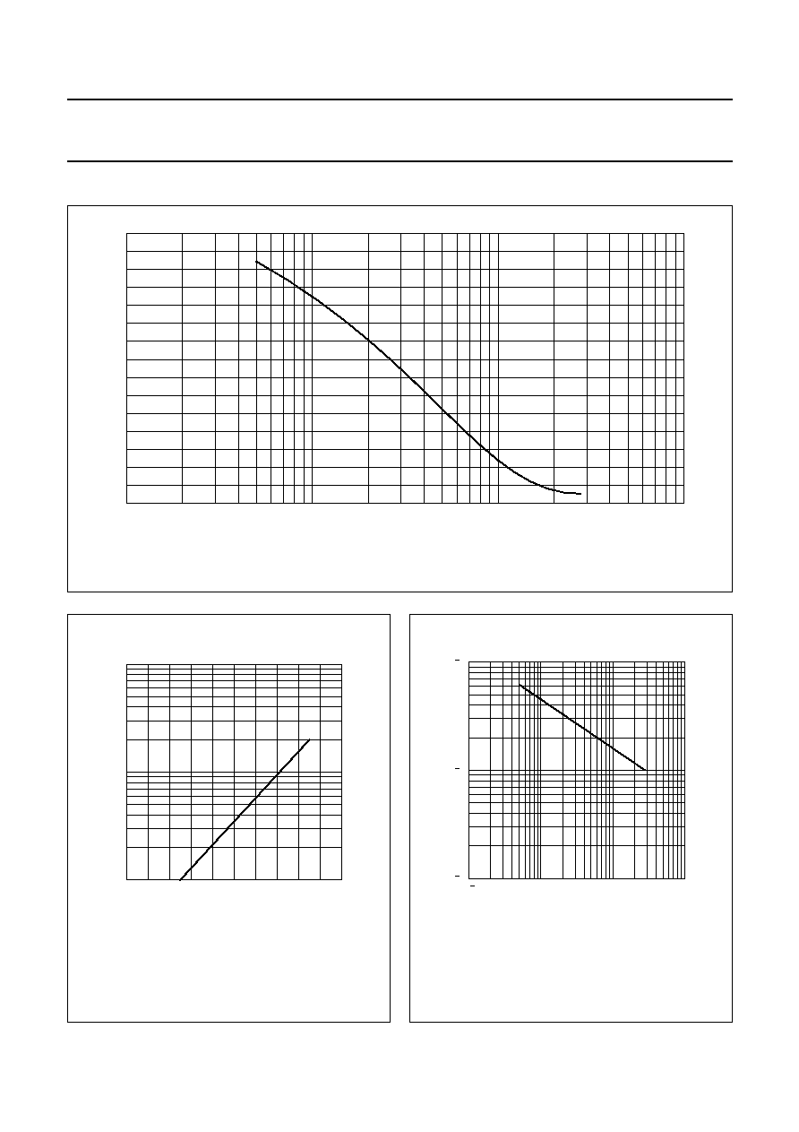
Fig.2 Diode capacitance as a function of reverse voltage; typical values.
f = 1 MHz; T
j
= 25
∞
C
.
handbook, full pagewidth
0
75
MRC283 - 1
10
2
10
1
10
-
1
25
50
Cd
(pF)
V
R
(V)
Fig.3
Reverse current as a function of junction
temperature; maximum values.
handbook, halfpage
100
0
10
MLC816
10
2
10
3
50
IR
(nA)
T ( C)
j
o
Fig.4
Temperature coefficient of diode
capacitance as a function of
reverse voltage; typical values.
T
j
= 0 to 85
∞
C.
handbook, halfpage
MLC815
1
10
10
2
10
3
10
4
10
5
10
1
(K
-
1
)
V (V)
R
d
TC
1996 May 03
4
Philips Semiconductors
Product specification
VHF variable capacitance diode
BB911/A
PACKAGE OUTLINE
DEFINITIONS
LIFE SUPPORT APPLICATIONS
These products are not designed for use in life support appliances, devices, or systems where malfunction of these
products can reasonably be expected to result in personal injury. Philips customers using or selling these products for
use in such applications do so at their own risk and agree to fully indemnify Philips for any damages resulting from such
improper use or sale.
Data sheet status
Objective specification
This data sheet contains target or goal specifications for product development.
Preliminary specification
This data sheet contains preliminary data; supplementary data may be published later.
Product specification
This data sheet contains final product specifications.
Limiting values
Limiting values given are in accordance with the Absolute Maximum Rating System (IEC 134). Stress above one or
more of the limiting values may cause permanent damage to the device. These are stress ratings only and operation
of the device at these or at any other conditions above those given in the Characteristics sections of the specification
is not implied. Exposure to limiting values for extended periods may affect device reliability.
Application information
Where application information is given, it is advisory and does not form part of the specification.
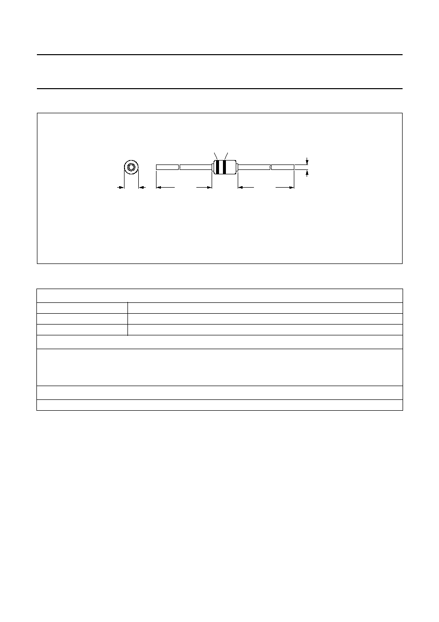
Dimensions in mm.
(1) Cathode side indicated by a red band on a black body.
(2) Additional white band.
Fig.5 SOD68 (DO-34).
1.6
max
25.4 min
25.4 min
3.04
max
0.55
max
MBC040
(1)
(2)