January 1995
2
Philips Semiconductors
Product specification
Programmable divide-by-n counter
HEF4059B
LSI
DESCRIPTION
The HEF4059B is a divide-by-n counter which can be
programmed to divide an input frequency by any number
n from 3 to 15 999. The output signal is a one clock-cycle
wide pulse and occurs at a rate equal to the input
frequency divided by
n. The single output (O) has TTL
drive capability. The down counter is preset by means of
16 jam inputs (J1 to J16); continued on next page.
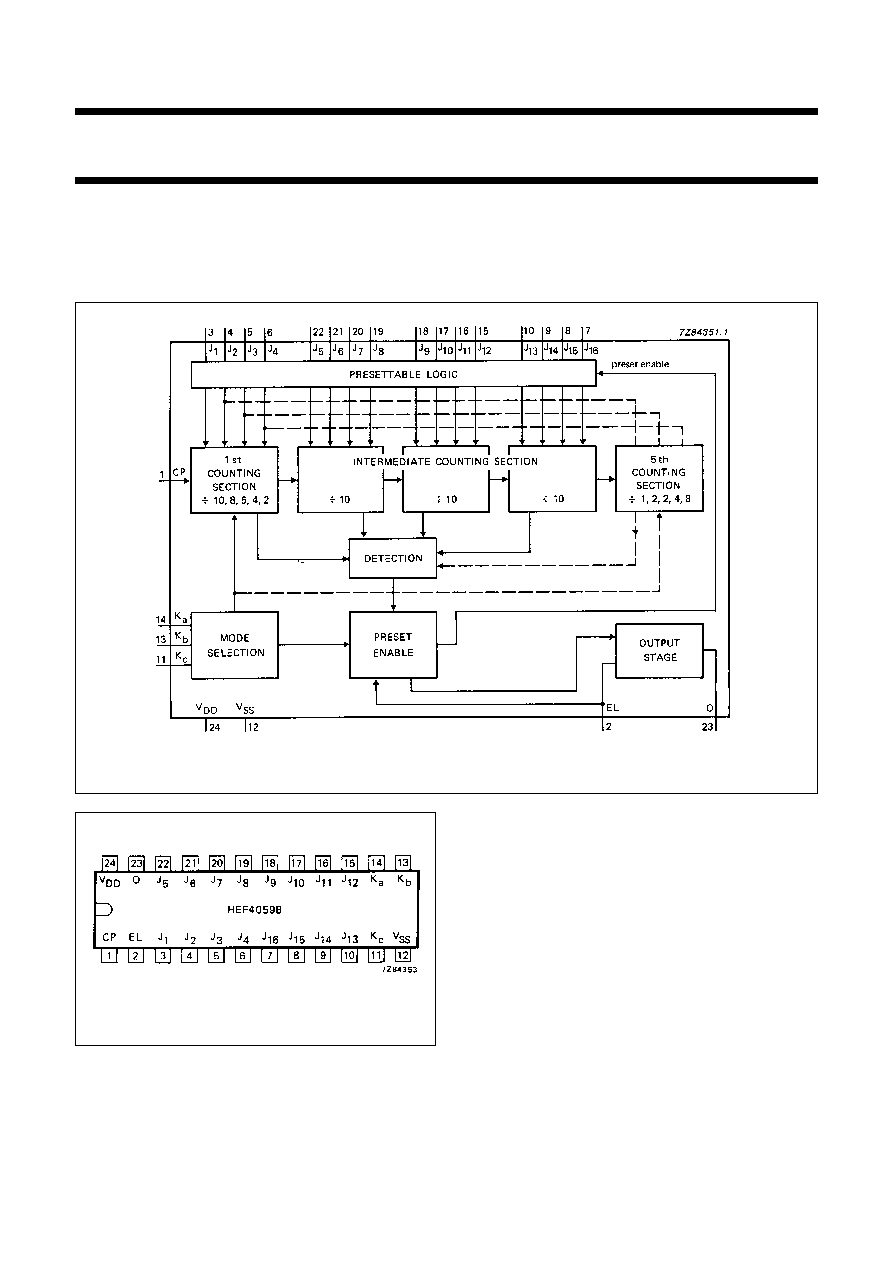
Fig.1 Functional block diagram.
FAMILY DATA, I
DD
LIMITS category LSI
See Family Specifications
Fig.2 Pinning diagram.
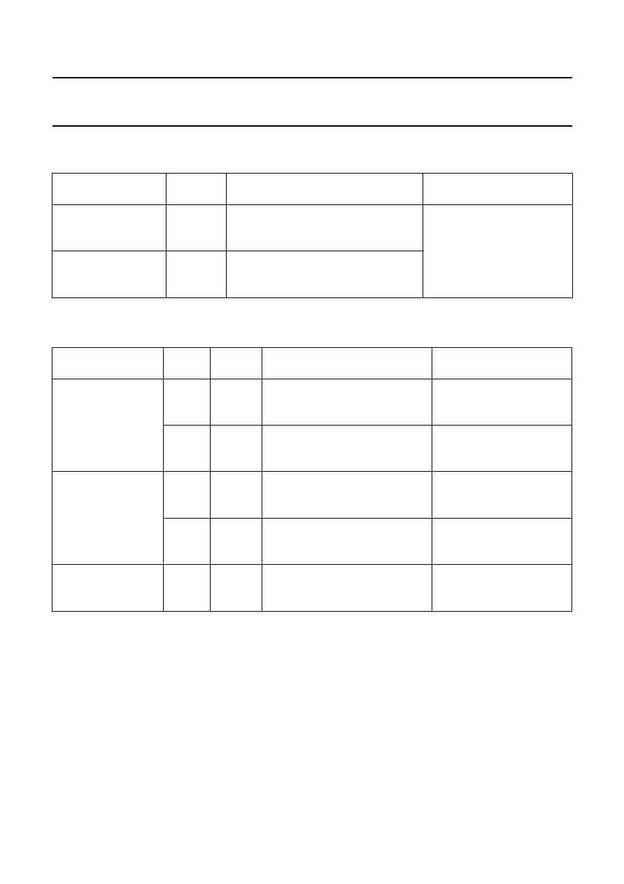
PINNING
CP
clock input
K
a
, K
b
, K
c
mode select inputs
J
1
to J
16
programmable jam inputs (BCD)
EL
latch enable input
O
divide-by-n output
HEF4059BP(N):
24-lead DIL; plastic (SOT101-1)
HEF4059BD(F):
24-lead DIL; ceramic (cerdip) (SOT94)
HEF4059BT(D):
24-lead SO; plastic (SOT137-1)
( ): Package Designator North America

January 1995
3
Philips Semiconductors
Product specification
Programmable divide-by-n counter
HEF4059B
LSI
The three mode selection inputs K
a
, K
b
and K
c
determine
the modulus (`divide-by' number) of the first and last
counting sections in accordance with Table 1.
Every time the first (fastest) counting section goes through
one cycle, it reduces, by 1, the number that has been
preset (jammed) into the three decades of the intermediate
counting section and into the last counting section (which
consists of flip-flops that are not needed for operating the
first counting section).
For example, in the
˜
2 mode, only one flip-flop is needed
in the first counting section. Therefore the last (5th)
counting section has three flip-flops that can be preset to a
maximum count of seven with a place value of thousands.
This counting mode is selected when K
a
, K
b
and K
c
are set
to HIGH. In this case input J
1
is used to preset the first
counting section and J
2
to J
4
are used to preset the last
(5th) counting section.
If
˜
10 mode is desired for the first section, K
a
is set HIGH,
K
b
to HIGH and K
c
to LOW. The jam inputs J
1
to J
4
are
used to preset the first counting section and there is no last
counting section. The intermediate counting section
consists of three cascaded BCD decade (
˜
10) counters,
presettable by means of the jam inputs J
5
to J
16
.
When clock pulses are applied to the clock input after a
number
n has been preset into the counter, the counter
counts down until the DETECTION circuit detects the zero
state. At this time the PRESET ENABLE circuit is enabled
to preset again the number
n into the counter and to
produce an output pulse.
The preset of the counter to a desired
˜
n is achieved as
follows:
n = (MODE*) (1000
◊
decade 5 preset
+
100
◊
decade 4 preset
+
10
◊
decade 3 preset
+
1
◊
decade 2 preset)
+
decade 1 preset.
* MODE = first counting section divider (10, 8, 5, 4 or 2).
To calculate preset values for any
n count, divide the
n count by the selected mode. The resultant is the
corresponding preset values of the 5th to the 2nd decade
with the remainder being equal to the 1st decade value.
If
n = 8479, and the selected mode = 5, the preset value
= 8479
˜
5 = 1695 with a remainder of 4, thus the jam
inputs must be set as follows:
preset value
n
mode
----------------
.
=
4
1
5
9
6
J
1
J
2
J
3
J
4
J
5
J
6
J
7
J
8
J
9
J
10
J
11
J
12
J
13
J
14
J
15
J
16
L
L
H
H
H
L
H
L
H
L
L
H
L
H
H
L
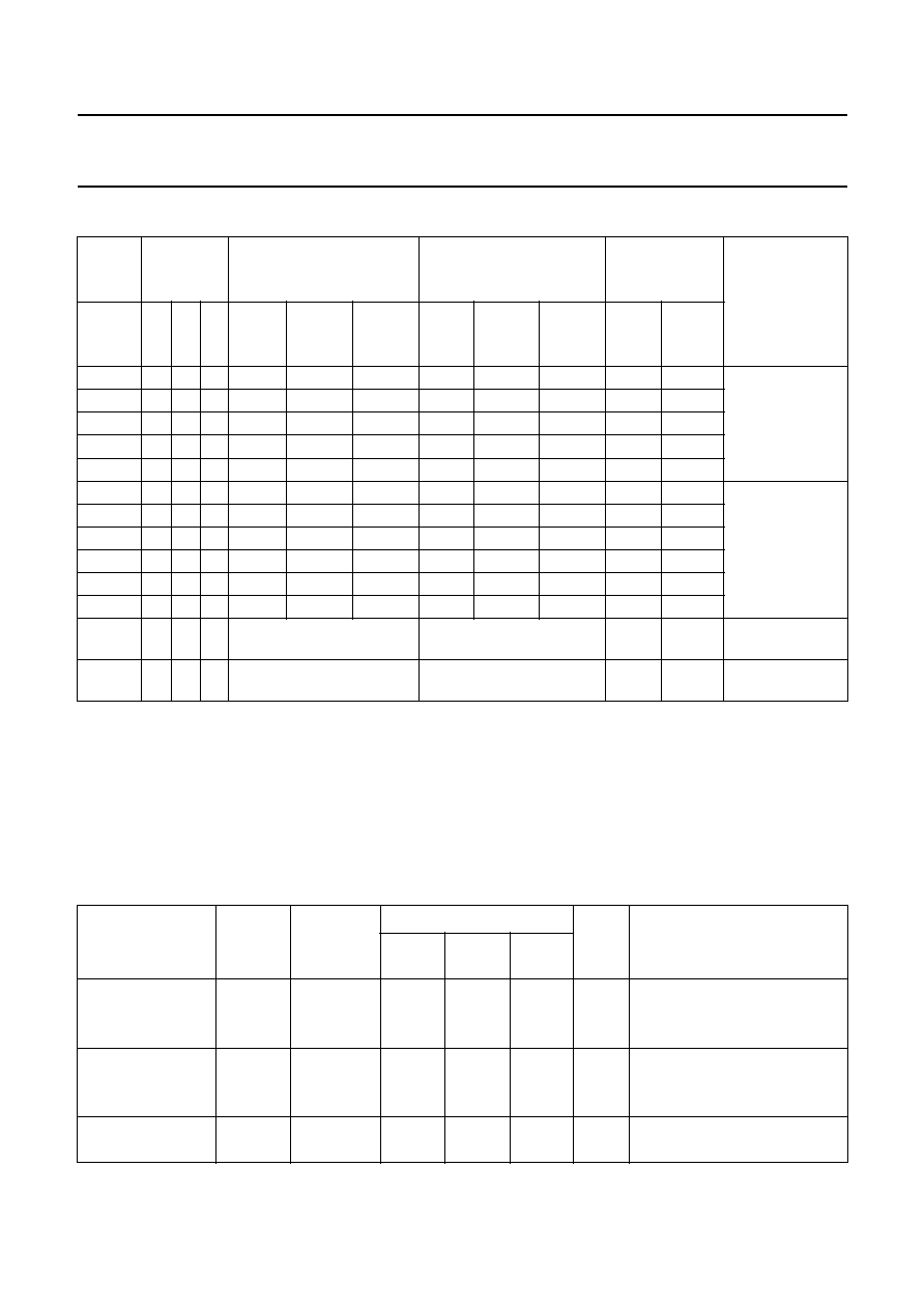
The mode select inputs permit frequency-synthesizer
channel separations of 10, 12,5, 20, 25 and 50 parts.
These inputs set the maximum value of
n at 9999 (when
the first counting section divides by 5 or 10) or at 15 999
(when the first counting section divides by 8, 4 or 2).
The three decades of the intermediate counting section
can be preset to a binary 15 instead of a binary 9. In this
case the first cycle of a counter consists of 15 count
pulses, the next cycles consisting of 10 count pulses. Thus
the place value of the three decades are still 1, 10 and 100.
For example, in the
˜
8 mode, the number from which the
intermediate counting section begins to count-down can
be preset to:
3rd
decade:
1500
2nd
decade:
150
1st
decade:
15
1665
The last counting section can be preset to a maximum of
1, with a place value of 1000. The total of these numbers
(2665) times 8 equals 21 320. The first counting section
can be preset to a maximum of 7. Therefore, 21 327 is the
maximum possible count in the
˜
8 mode. The highest
count of the various modes is shown in Table 1, in the
column entitled `extended counter range'. Control inputs
K
b
and K
c
can be used to initiate and lock the counter in
the `master preset' mode. In this condition the flip-flops in
the counter are preset in accordance with the jam inputs
and the counter remains in that mode as long as K
b
and
K
c
both remain LOW. The counter begins to run down from
the preset state when a counting mode other than the
`master preset' mode is selected. Whenever the `master
preset' mode is used, control signals K
b
= L and K
c
= L
must be applied for at least 3 full clock pulses. After the
master preset mode inputs have been changed to one of
the counting modes, the next positive-going clock
transition changes an internal flip-flop so that the
count-down can begin at the second positive-going clock
transition. Thus, after a `master preset' mode, there is
always one extra count before the output goes HIGH.
January 1995
4
Philips Semiconductors
Product specification
Programmable divide-by-n counter
HEF4059B
LSI
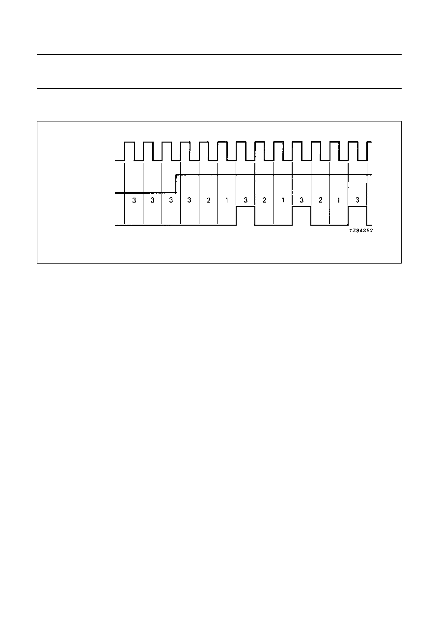
Figure 3 illustrates the operation of the counter in mode
˜
8 starting from the preset state 3.
Fig.3 Total count of 3.
CP INPUT
K
c
INPUT
(K
a
, K
b
= LOW)
internal state
of counter
O OUTPUT
If the `master preset' mode is started two clock cycles or
less before an output pulse, the output pulse will appear at
the time due. If the `master preset' mode is not used the
counter is preset in accordance with the `jam inputs when
the output pulse appears. A HIGH level at the latch enable
input (EL) will cause the counter output to go HIGH once
an output pulse occurs, and remain in the HIGH state until
EL input returns to LOW. If the EL input is LOW, the output
pulse will remain HIGH for only one cycle of the clock input
signal.
When K
a
= L, K
b
= H, K
c
= L and EL = L, the counter
operates in the `preset inhibit' mode, with which the
dividend of the counter is fixed to 10 000, independent of
the state of the jam inputs.
When in the same state of mode select inputs EL = H, the
counter operates in the normal
˜
10 mode, however,
without the latch operation at the output.
Schmitt-trigger action in the clock input makes the circuit
highly tolerant to slower clock rise and fall times.