 | ÐлекÑÑоннÑй компоненÑ: HEF4522BN | СкаÑаÑÑ:  PDF PDF  ZIP ZIP |
Äîêóìåíòàöèÿ è îïèñàíèÿ www.docs.chipfind.ru

DATA SHEET
Product specification
File under Integrated Circuits, IC04
January 1995
INTEGRATED CIRCUITS
HEF4522B
MSI
Programmable 4-bit BCD down
counter
For a complete data sheet, please also download:
·
The IC04 LOCMOS HE4000B Logic
Family Specifications HEF, HEC
·
The IC04 LOCMOS HE4000B Logic
Package Outlines/Information HEF, HEC
January 1995
2
Philips Semiconductors
Product specification
Programmable 4-bit BCD down counter
HEF4522B
MSI
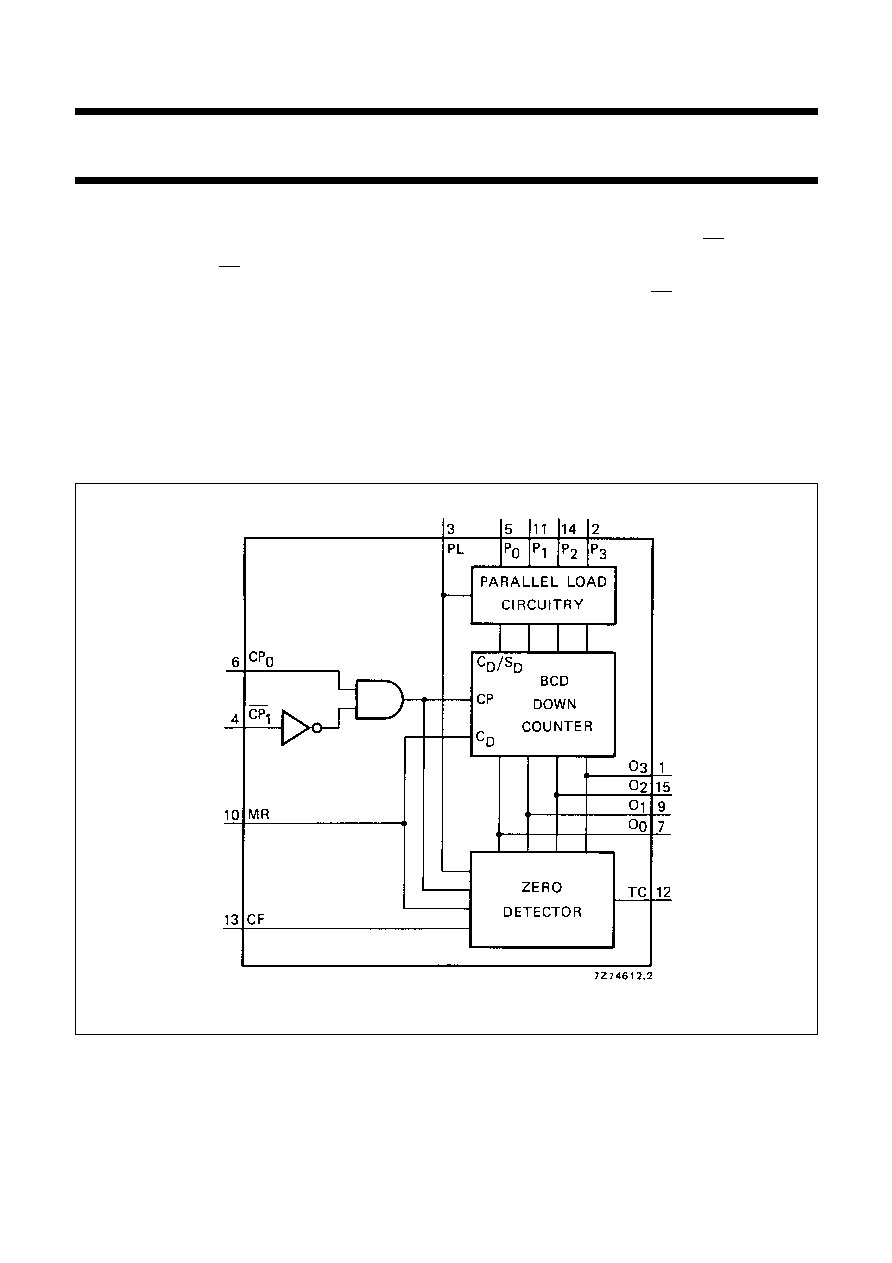
DESCRIPTION
The HEF4522B is a synchronous programmable 4-bit
BCD down counter with an active HIGH and an active
LOW clock input (CP
0
, CP
1
), an asynchronous parallel
load input (PL), four parallel inputs (P
0
to P
3
), a cascade
feedback input (CF), four buffered parallel outputs (O
0
to
O
3
), a terminal count output (TC) and an overriding
asynchronous master reset input (MR).
This device is a programmable, cascadable down counter
with a decoded TC output for divide-by-n applications. In
single stage applications the TC output is connected to PL.
CF allows cascade divide-by-n operation with no
additional gates required.
Information on P
0
to P
3
is loaded into the counter while PL
is HIGH, independent of all other input conditions except
MR, which must be LOW. When PL and CP
1
are LOW, the
counter advances on a LOW to HIGH transition of CP
0
.
When PL is LOW and CP
0
is HIGH, the counter advances
on a HIGH to LOW transition of CP
1
. TC is HIGH when the
counter is in the zero state (O
0
= O
1
= O
2
= O
3
= LOW)
and CF is HIGH and PL is LOW. A HIGH on MR resets the
counter (O
0
to O
3
= LOW) independent of other input
conditions.
Schmitt-trigger action in the clock input makes the circuit
highly tolerant to slower clock rise and fall times.
FAMILY DATA, I
DD
LIMITS category MSI
See Family Specifications
Fig.1 Functional diagram.

January 1995
3
Philips Semiconductors
Product specification
Programmable 4-bit BCD down counter
HEF4522B
MSI
Fig.2 Pinning diagram.
HEF4522BP(N):
16-lead DIL; plastic
(SOT38-1)
HEF4522BD(F):
16-lead DIL; ceramic (cerdip)
(SOT74)
HEF4522BT(D):
16-lead SO; plastic
(SOT109-1)
( ): Package Designator North America
PINNING
PL
parallel load input
P
0
to P
3
parallel inputs
CF
cascade feedback input
CP
0
clock input (LOW to HIGH, triggered)
CP
1
clock input (HIGH to LOW, triggered)
MR
asynchronous master reset input
TC
terminal count output
O
0
to O
3
buffered parallel outputs
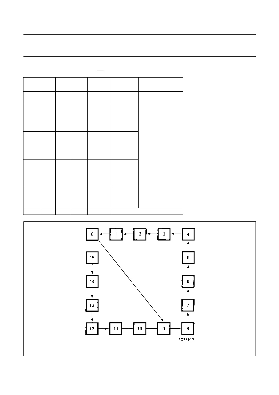
COUNTING MODE
CF = HIGH; PL = LOW; MR = LOW
COUNT
OUTPUTS
O
3
O
2
O
1
O
0
9
H
L
L
H
8
H
L
L
L
7
L
H
H
H
6
L
H
H
L
5
L
H
L
H
4
L
H
L
L
3
L
L
H
H
2
L
L
H
L
1
L
L
L
H
0
L
L
L
L
FUNCTION TABLE
Notes
1. H = HIGH state (the more positive voltage)
L = LOW state (the less positive voltage)
X = state is immaterial
= positive-going transition
= negative-going transition
MR
PL
CP
0
CP
1
MODE
H
X
X
X
reset (asynchronous)
L
H
X
X
preset (asynchronous)
L
L
H
no change
L
L
L
no change
L
L
X
no change
L
L
X
no change
L
L
L
counter advances
L
L
H
counter advances
January 1995
4
Philips Semiconductors
Product specification
Programmable 4-bit BCD down counter
HEF4522B
MSI
SINGLE STAGE OPERATION
Divide-by-n; MR = LOW; CF = HIGH; CP
1
= LOW
PL
P
3
P
2
P
1
P
0
DIVIDE
BY
TC OUTPUT
PULSE WIDTH
L
X
X
X
X
10
one clock
period
TC
H
H
H
H
15
clock pulse
HIGH
TC
H
H
H
L
14
TC
H
H
L
H
13
TC
H
H
L
L
12
TC
H
L
H
H
11
TC
H
L
H
L
10
TC
H
L
L
H
9
TC
H
L
L
L
8
TC
L
H
H
H
7
TC
L
H
H
L
6
TC
L
H
L
H
5
TC
L
H
L
L
4
TC
L
L
H
H
3
TC
L
L
H
L
2
TC
L
L
L
H
1
TC
L
L
L
L
no operation
Fig.3 State diagram.
January 1995
5
Philips Semiconductors
Product specification
Programmable 4-bit BCD down counter
HEF4522B
MSI
This text is here in white to force landscape pages to be rotated correctly when browsing through the pdf in the Acrobat reader.This text is here in
_
white to force landscape pages to be rotated correctly when browsing through the pdf in the Acrobat reader.This text is here inThis text is here in
white to force landscape pages to be rotated correctly when browsing through the pdf in the Acrobat reader. white to force landscape pages to be ...
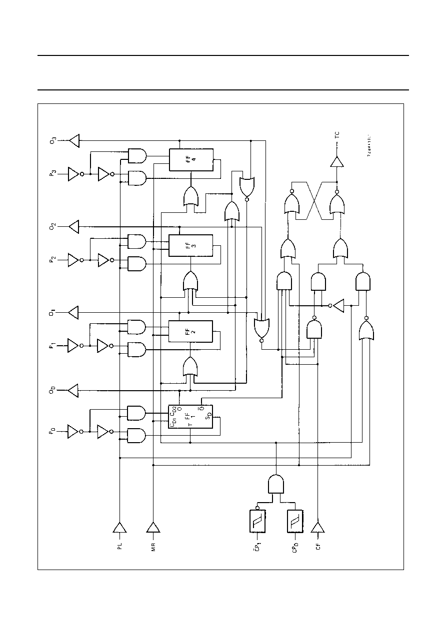
Fig.4 Logic diagram.

January 1995
6
Philips Semiconductors
Product specification
Programmable 4-bit BCD down counter
HEF4522B
MSI
AC CHARACTERISTICS
V
SS
= 0 V; T
amb
= 25
°
C; input transition times
20 ns
AC CHARACTERISTICS
V
SS
= 0 V; T
amb
= 25
°
C; C
L
= 50 pF; input transition times
20 ns
V
DD
V
TYPICAL FORMULA FOR P (
µ
W)
Dynamic power
5
1000 f
i
+
(f
o
C
L
)
×
V
DD
2
where
dissipation per
10
4000 f
i
+
(f
o
C
L
)
×
V
DD
2
f
i
= input freq. (MHz)
package (P)
15
10 000 f
i
+
(f
o
C
L
)
×
V
DD
2
f
o
= output freq. (MHz)
C
L
= load capacitance (pF)
(f
o
C
L
) = sum of outputs
V
DD
= supply voltage (V)
V
DD
V
SYMBOL
MIN.
TYP.
MAX.
TYPICAL EXTRAPOLATION
FORMULA
Propagation delays
CP
0
, CP
1
O
n
5
150
300
ns
123 ns
+
(0,55 ns/pF) C
L
HIGH to LOW
10
t
PHL
65
130
ns
54 ns
+
(0,23 ns/pF) C
L
15
50
100
ns
42 ns
+
(0,16 ns/pF) C
L
5
150
300
ns
123 ns
+
(0,55 ns/pF) C
L
LOW to HIGH
10
t
PLH
65
130
ns
54 ns
+
(0,23 ns/pF) C
L
15
50
100
ns
42 ns
+
(0,16 ns/pF) C
L
CP
0
, CP
1
TC
5
210
420
ns
183 ns
+
(0,55 ns/pF) C
L
HIGH to LOW
10
t
PHL
90
180
ns
79 ns
+
(0,23 ns/pF) C
L
15
70
140
ns
62 ns
+
(0,16 ns/pF) C
L
5
210
420
ns
183 ns
+
(0,55 ns/pF) C
L
LOW to HIGH
10
t
PLH
90
180
ns
79 ns
+
(0,23 ns/pF) C
L
15
70
140
ns
62 ns
+
(0,16 ns/pF) C
L
PL
O
n
5
200
400
ns
173 ns
+
(0,55 ns/pF) C
L
HIGH to LOW
10
t
PHL
80
160
ns
69 ns
+
(0,23 ns/pF) C
L
15
60
120
ns
52 ns
+
(0,16 ns/pF) C
L
5
180
360
ns
153 ns
+
(0,55 ns/pF) C
L
LOW to HIGH
10
t
PLH
70
140
ns
59 ns
+
(0,23 ns/pF) C
L
15
50
100
ns
42 ns
+
(0,16 ns/pF) C
L
MR
O
n
5
140
280
ns
113 ns
+
(0,55 ns/pF) C
L
HIGH to LOW
10
t
PHL
55
110
ns
44 ns
+
(0,23 ns/pF) C
L
15
40
80
ns
32 ns
+
(0,16 ns/pF) C
L
Output transition times
5
60
120
ns
10 ns
+
(1,0 ns/pF) C
L
HIGH to LOW
10
t
THL
30
60
ns
9 ns
+
(0,42 ns/pF) C
L
15
20
40
ns
6 ns
+
(0,28 ns/pF) C
L
5
60
120
ns
10 ns
+
(1,0 ns/pF) C
L
LOW to HIGH
10
t
TLH
30
60
ns
9 ns
+
(0,42 ns/pF) C
L
15
20
40
ns
6 ns
+
(0,28 ns/pF) C
L

January 1995
7
Philips Semiconductors
Product specification
Programmable 4-bit BCD down counter
HEF4522B
MSI
AC CHARACTERISTICS
V
SS
= 0 V; T
amb
= 25
°
C; C
L
= 50 pF; input transition times
20 ns
Note
1. In the divide-by-n mode (PL connected to TC), one has to observe the maximum HIGH to LOW propagation delay
for CP to TC, before applying the next clock pulse.
V
DD
V
SYMBOL
MIN.
TYP.
MAX.
Minimum clock
5
80
40
ns
see also waveforms
Figs 5 and 6
pulse width; CP
0
10
t
WCPL
40
20
ns
LOW
15
30
15
ns
Minimum clock
5
80
40
ns
pulse width; CP
1
10
t
WCPH
40
20
ns
HIGH
15
30
15
ns
Minimum PL
5
100
50
ns
pulse width; HIGH
10
t
WPLH
40
20
ns
15
32
16
ns
Minimum MR
5
130
65
ns
pulse width; HIGH
10
t
WMRH
50
25
ns
15
40
20
ns
Hold time
5
30
5
ns
P
n
PL
10
t
hold
20
5
ns
15
15
5
ns
Set-up time
5
30
0
ns
P
n
PL
10
t
su
20
0
ns
15
15
0
ns
Maximum clock
5
6
12
MHz
see note 1
pulse frequency
10
f
max
12
25
MHz
PL = LOW
15
16
32
MHz

January 1995
8
Philips Semiconductors
Product specification
Programmable 4-bit BCD down counter
HEF4522B
MSI
Fig.5
Waveforms showing minimum PL pulse width, propagation delays for PL, P
n
to O
n
and hold time for PL to P
n
.
Fig.6
Waveforms showing minimum CP
0
and CP
1
pulse widths, propagation delays for CP
0
, CP
1
to O
n
and TC.

January 1995
9
Philips Semiconductors
Product specification
Programmable 4-bit BCD down counter
HEF4522B
MSI
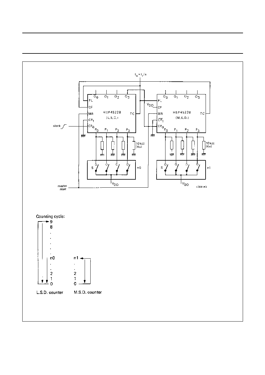
APPLICATION INFORMATION
Some examples of applications for the HEF4522B are:
·
Divide-by-n counter
·
Programmable frequency divider
Fig.7
Typical application of two HEF4522B circuits in a 2-stage programmable down counter (one cycle). S are
thumbwheel switches; when open: LOW state.
Counting cycle:
January 1995
10
Philips Semiconductors
Product specification
Programmable 4-bit BCD down counter
HEF4522B
MSI
Fig.8
Typical application of two HEF4522B circuits in a 2-stage programmable frequency divider. S are
thumbwheel switches; when open: LOW state.
Counting cycle:
Document Outline
- DESCRIPTION
- FAMILY DATA, IDD LIMITS category MSI
- PINNING
- COUNTING MODE
- FUNCTION TABLE
- SINGLE STAGE OPERATION
- AC CHARACTERISTICS
- APPLICATION INFORMATION