Document Outline
- GENERAL DESCRIPTION
- FEATURES
- APPLICATIONS
- SIMPLIFIED SYSTEM DIAGRAM
- ORDERING INFORMATION
- PIN DESCRIPTION
- MAXIMUM RATINGS
- DC ELECTRICAL CHARACTERISTICS
- AC ELECTRICAL CHARACTERISTICS
- TYPICAL PERFORMANCE CURVES
- TECHNICAL DESCRIPTION
- Timing diagram
- Application information
- Parametric testing
- PACKING METHOD
- PACKAGE OUTLINE
- REVISION HISTORY
- Data sheet status
- Definitions
- Disclaimers

Philips
Semiconductors
NE56604-42
System reset with built-in Watchdog timer
Product data
Supersedes data of 2001 Aug 22
2003 Oct 15
INTEGRATED CIRCUITS
Philips Semiconductors
Product data
NE56604-42
System reset with built-in Watchdog timer
2
2003 Oct 15
GENERAL DESCRIPTION
The NE56604-42 is designed to generate a reset signal at a
threshold voltage of 4.2 V for a variety of microprocessor and logic
systems. Accurate reset signals are generated during momentary
power interruptions, or whenever power supply voltages sag to
intolerable levels. The NE56604-42 has a built-in Watchdog Timer to
monitor the microprocessor and ensure it is operating properly. Any
abnormal system operations due to microprocessor malfunctions
are terminated by a system reset generated by the Watchdog. The
NE56604-42 has a Watchdog monitoring time of 100 ms (typical).
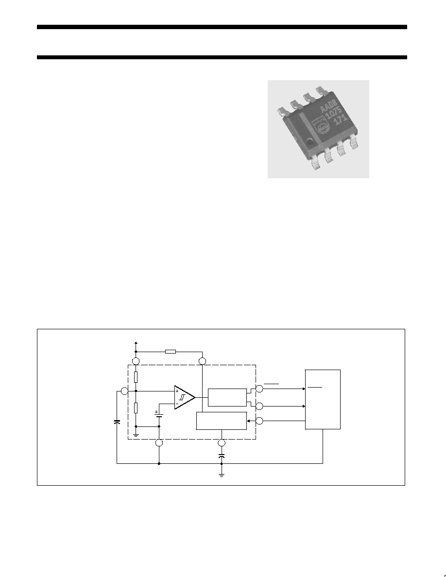
The NE56604-42 is offered in the SO8 surface mount package
(SOP005).
FEATURES
∑
Both positive and negative logic reset output signals are available
∑
Accurate threshold detection
∑
Internal power-on reset delay
∑
Internal Watchdog timer programmable with external resistor
∑
Watchdog monitoring time of 100 ms (typical)
∑
Reset assertion with V
CC
down to 0.8 V
DC
(typical)
∑
Few external components required.
APPLICATIONS
∑
Microcomputer systems
∑
Logic systems.
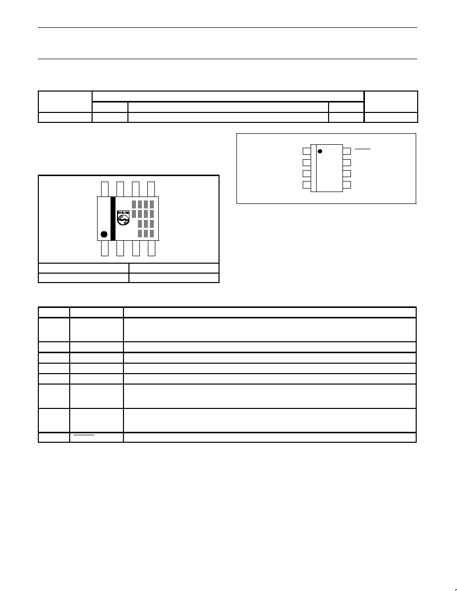
SIMPLIFIED SYSTEM DIAGRAM
SL01281
RESET
GENERATOR
PROGRAMMABLE
WATCHDOG TIMER
3
CLK
2
RESET
8
RESET
1
C
T
V
REF
4
GND
R
7
R
C
V
S
6
R
CT
R
CT
V
CC
5
GND
CLK
RESET
RESET
LOGIC
SYSTEM
NE56604-42
Figure 1. Simplified system diagram.
Philips Semiconductors
Product data
NE56604-42
System reset with built-in Watchdog timer
2003 Oct 15
3
ORDERING INFORMATION
TYPE NUMBER
PACKAGE
TEMPERATURE
TYPE NUMBER
NAME
DESCRIPTION
VERSION
RANGE
NE56604-42D
SO8
plastic small outline package; 8 leads; body width 3.9 mm
SOP005
≠20 to +70
∞
C
Part number marking
The package is marked with a four letter code in the first line to the
right of the logo. The first three letters designate the product. The
fourth letter, represented by `x', is a date tracking code. The
remaining two or three lines of characters are internal manufacturing
codes.
2
3
1
5
4
6
7
8
Part number
Marking
NE56604-42
A A D x
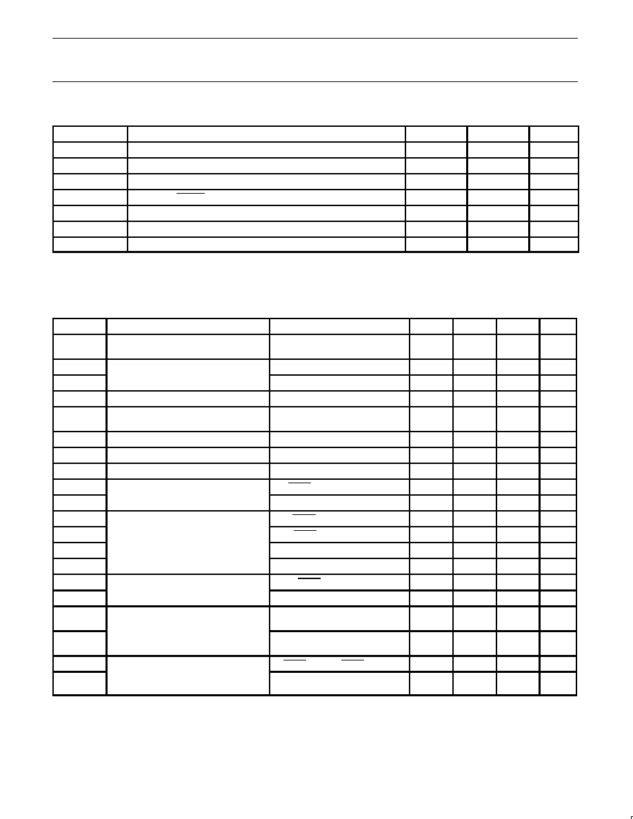
PIN CONFIGURATION
SL01280
1
2
3
4
8
7
6
5
TOP VIEW
SO8
C
T
RESET
CLK
GND
RESET
V
S
R
CT
V
CC
Figure 2. Pin configuration.
PIN DESCRIPTION
PIN
SYMBOL
DESCRIPTION
1
C
T
t
WDM
, t
WDR
, t
PR
adjustment pin.
t
WDM
, t
WDR
, t
PR
times are dependent on the value of external C
T
capacitor used. See Figure 20 (Timing
Diagram) for definition of t
WDM
, t
WDR
, t
PR
times.
2
RESET
Reset HIGH output pin.
3
CLK
Clock input pin from logic system for Watchdog timer.
4
GND
Circuit ground.
5
V
CC
Power supply pin for circuit.
6
R
CT
Watchdog timer control and program pin.
Serves to ENABLE the Watchdog function when connected to pull-up resistor (R
CT
) to V
CC
, and DISABLE
the Watchdog when connected to ground. Used in conjunction with C
T
pin to program t
WDM
time.
7
V
S
Detection threshold adjustment pin.
The detection threshold can be increased by connecting this pin to V
CC
with a pull-up resistor. The detection
threshold can be decreased by connecting this pin to ground with a pull-down resistor.
8
RESET
Reset LOW output pin.
Philips Semiconductors
Product data
NE56604-42
System reset with built-in Watchdog timer
2003 Oct 15
4
MAXIMUM RATINGS
SYMBOL
PARAMETER
MIN.
MAX.
UNIT
V
CC
Power supply voltage
≠0.3
10
V
V
VS
V
S
pin voltage
≠0.3
10
V
V
CLK
CLK pin voltage
≠0.3
10
V
V
OH
RESET and RESET pin voltage
≠0.3
10
V
T
oper
Operating temperature
≠20
70
∞
C
T
stg
Storage temperature
≠40
125
∞
C
P
Power dissipation
≠
250
mW
DC ELECTRICAL CHARACTERISTICS
Characteristics measured with V
CC
= 5.0 V, and T
amb
= 25
∞
C, unless otherwise specified.
See Figure 26 (Test circuit 1) for test configuration used for DC parameters.
SYMBOL
PARAMETER
CONDITIONS
MIN.
TYP.
MAX.
UNIT
I
CC
Supply current during Watchdog timer
operation
≠
0.7
1.0
mA
V
SL
Reset detection threshold
V
S
= open; V
CC
= falling
4.05
4.20
4.35
V
V
SH
V
S
= open; V
CC
= rising
4.15
4.30
4.45
V
V
S
/
T
amb
Temperature coefficient of reset threshold
≠20
∞
C
T
amb
70
∞
C
≠
±
0.01
≠
%/
∞
C
V
hys
Threshold hysteresis
V
hys
= V
SH
(rising V
CC
) ≠ V
SL
(falling V
CC
)
50
100
150
mV
V
TH
CLK input threshold
0.8
1.2
2.0
V
I
IH
CLK input current, HIGH-level
V
CLK
= 5.0 V
≠
0
1.0
µ
A
I
IL
CLK input current, LOW-level
V
CLK
= 0 V
≠20
≠10
≠3.0
µ
A
V
OH1
Output voltage, HIGH-level
I
RESET
= ≠5.0
µ
A; V
S
= open
4.5
4.8
≠
V
V
OH2
I
RESET
current = ≠5.0 mA; V
S
= 0 V
4.5
4.8
≠
V
V
OL1
Output voltage, LOW-level
I
RESET
= 3.0 mA; V
S
= 0 V
≠
0.2
0.4
V
V
OL2
I
RESET
= 10 mA; V
S
= 0 V
≠
0.3
0.5
V
V
OL3
I
RESET
= 0.5 mA; V
S
= open
≠
0.2
0.4
V
V
OL4
I
RESET
= 1.0 mA; V
S
= open
≠
0.3
0.5
V
I
OL1
Output sink current
V
RESET
= 1.0 V; V
S
= 0 V
10
16
≠
mA
I
OL2
V
RESET
= 1.0 V; V
S
= open
1.0
2.0
≠
mA
I
CT1
C
T
charge current (Note 1)
V
CT
= 1.0 V; R
CT
= open during
Watchdog operation
≠0.8
≠1.2
≠2.4
µ
A
I
CT2
V
CT
= 1.0 V;
during power-on reset operation
≠0.8
≠1.2
≠2.4
µ
A
V
CCL1
Supply voltage to assert reset operation
V
RESET
= 0.4 V; I
RESET
= 0.2 mA
≠
0.8
1.0
V
V
CCL2
V
RESET
= V
CC
≠ 0.1 V;
1 M
resistor (pin 2 to GND)
≠
0.8
1.0
V
NOTE:
1. I
CT
source current is determined by the value of the R
CT
pull-up resistor to V
CC
.
Philips Semiconductors
Product data
NE56604-42
System reset with built-in Watchdog timer
2003 Oct 15
5
AC ELECTRICAL CHARACTERISTICS
Characteristics measured with V
CC
= 5.0 V, and T
amb
= 25
∞
C, unless otherwise specified.
See Figure 27 (Test circuit 2) for test configuration used for AC parameters.
SYMBOL
PARAMETER
CONDITIONS
MIN.
TYP.
MAX.
UNIT
t
P1
Minimum power supply pulse width for
detection
4.0 V
negative-going V
CC
pulse
5.0 V
8.0
≠
≠
µ
s
t
CLKW
Clock input pulse width
3.0
≠
≠
µ
s
t
CLK
Clock input cycle
20
≠
≠
µ
s
t
WDM
Watchdog monitoring time (Notes 1, 6)
C
T
= 0.1
µ
F; R
CT
= open
50
100
150
ms
t
WDR
Watchdog reset time (Notes 2, 6)
C
T
= 0.1
µ
F
1.0
2.0
3.0
ms
t
PR
Power-on reset delay time (Notes 3, 6)
V
CC
= rising from 0 V; C
T
= 0.1
µ
F
50
100
150
ms
t
PD1
Reset propagation delay time (Note 4)
RESET: R
L1
= 2.2 k
; C
L1
= 100 pF
≠
2.0
10
µ
s
t
PD2
RESET: R
L2
= 10 k
; C
L2
= 20 pF
≠
3.0
10
µ
s
t
R1
Reset rise time (Note 5)
RESET: R
L1
= 2.2 k
; C
L1
= 100 pF
≠
1.0
1.5
µ
s
t
R2
RESET: R
L2
= 10 k
; C
L2
= 20 pF
≠
1.0
1.5
µ
s
t
F1
Reset fall time (Note 5)
RESET: R
L1
= 2.2 k
; C
L1
= 100 pF
≠
0.1
0.5
µ
s
t
F2
RESET: R
L2
= 10 k
; C
L2
= 20 pF
≠
0.5
1.0
µ
s
NOTES:
1. `Watchdog monitoring time' is the duration from the last pulse (negative-going edge) of the timer clear clock pulse until reset output pulse
occurs (see Figure 20). A reset signal is output if a clock pulse is not input during this time. Watchdog monitoring time can be modified by
changing the value of the R
CT
pull-up resistor. Monitoring time adjustments are shown in Figure 25.
2. `Watchdog reset time' is the reset pulse width (see Figure 20).
3. `Power-on reset delay time' is the duration measured from the time V
CC
exceeds the upper detection threshold (V
SH
) and power-on reset
release is experienced (RESET output HIGH; RESET output LOW).
4. `Reset response time' is the duration from when the supply voltage sags below the lower detection threshold (V
SL
) and reset occurs (RESET
output LOW, RESET output HIGH).
5. Reset rise and fall times are measured at 10% and 90% output levels.
6. Watchdog monitoring time (t
WDM
), Watchdog reset time (t
WDR
), and power-on reset delay time (t
PR
) during power-on can be modified by
varying the C
T
capacitance. The times can be approximated by applying the following formula. The recommended range for C
T
is 0.001
µ
F
to 10
µ
F.
Formula 1.
Calculation for approximate t
PR
, t
WDM
, and t
WDR
values:
t
PR
(ms)
1000
◊
C
T
(
µ
F)
t
WDM
(ms)
1000
◊
C
T
(
µ
F)
t
WDR
(ms)
20
◊
C
T
(
µ
F)
Example:
When C
T
= 0.1
µ
F and R
CT
= open:
t
PR
100 ms
t
WDM
100 ms
t
WDR
2.0 ms