 | –≠–ª–µ–∫—Ç—Ä–æ–Ω–Ω—ã–π –∫–æ–º–ø–æ–Ω–µ–Ω—Ç: SA5752 | –°–∫–∞—á–∞—Ç—å:  PDF PDF  ZIP ZIP |
Document Outline
- DESCRIPTION
- FEATURES
- PIN CONFIGURATION
- BENEFITS
- APPLICATIONS
- ORDERING INFORMATION
- PIN DESCRIPTIONS
- BLOCK DIAGRAM
- ABSOLUTE MAXIMUM RATINGS
- DC ELECTRICAL CHARACTERISTICS
- AC ELECTRICAL CHARACTERISTICS
- TYPICAL PERFORMANCE CHARACTERISTICS
- PACKAGE OUTLINE
- DEFINITIONS
Philips Semiconductors
SA5752
Audio processor ≠ companding, VOX and
amplifier section
Product Specification
Replaces data of December 6, 1993
1997 Nov 07
RF COMMUNICATIONS PRODUCTS
IC17 Data Handbook
Philips Semiconductors
Product specification
SA5752
Audio processor ≠ companding, VOX and amplifier section
2
1997 Nov 07
853-1721 18666
DESCRIPTION
The SA5752 is a high performance low power audio signal
processing system especially designed to meet the requirements for
small size and low voltage operation of hand-held equipment. The
SA5752 subsystem includes a low noise microphone preamplifier
with adustable gain, a noise cancellation switching amplifier with
adjustable threshold, a voice operated transmitter (VOX) switch,
VOX control, an audio compressor with buffered input, audio
expandor, and an internal bandgap voltage regulator with power
down capability. When used with Philips Semiconductors' SA5753,
the complete audio processing function of an AMPS or TACS
cellular telephone is easily implemented. The system also meets
the requirements of the proposed NAMPS or NTACS specifications.
The SA5752 can also be used without the SA5753 in a wide variety
of radio communications applications.
FEATURES
∑
Operating voltage range: 2V to 5.5V
∑
Miniature SSOP
∑
High performance
∑
Adjustable VOX and noise cancellation threshold
∑
Adjustable gain preamplifier
∑
Audio companding
∑
ESD protected
∑
Open collector VOX output
∑
Logic inputs CMOS compatible
∑
Power down mode
∑
Few external components
∑
Meets AMPS/TACS/NAMPS/NTACS requirements
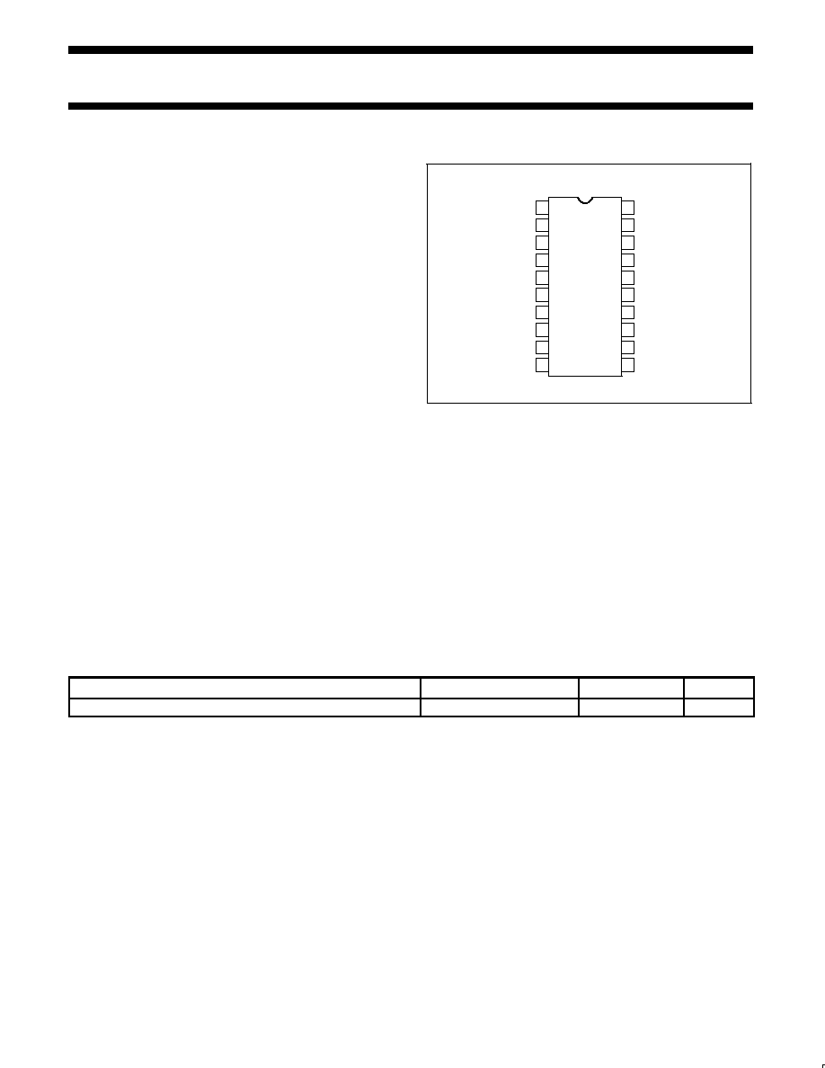
PIN CONFIGURATION
MICIN
RECTGRES
VOXOUT
VOXTR
GND
VREF
EXPOUT
HPDN
VOXCTL
COMPCAP2
COMPCAP3
NCANOUT
DK PACKAGE
1
2
3
4
5
6
7
8
9
10
11
12
13
14
20
19
18
17
16
15
PREAMPGRES
NCANCAP
VCC
EXPCAP
COMPIN
COMPCAP1
COMPOUT
EXPIN
SA5752
SR00659
Figure 1. Pin Configuration
BENEFITS
∑
Very compact applications
∑
Long battery life in portable equipment
∑
Complete cellular audio function with the SA5753
APPLICATIONS
∑
Cellular radio
∑
Mobile communications
∑
High performance cordless telephones
∑
2-way radio
ORDERING INFORMATION
DESCRIPTION
TEMPERATURE RANGE
ORDER CODE
DWG #
20-Pin Plastic Shrink Small Outline Package (SSOP)
-40 to +85
∞
C
SA5752DK
SOT266-1

Philips Semiconductors
Product specification
SA5752
Audio processor ≠ companding, VOX and amplifier section
1997 Nov 07
3
PIN DESCRIPTIONS
PIN NO.
SYMBOL
DESCRIPTION
1
MIC
IN
Microphone input
2
PREAMP
GRES
Preamplifier gain resistor
3
RECT
GRES
Rectifier gain resistor
4
NCAN
CAP
Noise cancellation timing capacitor
5
VOX
OUT
Voice operated transmission output
6
VOX
TR
Voice operated transmission threshold resistor
7
GND
Ground
8
V
REF
Reference voltage
9
V
CC
Positive supply
10
EXP
CAP
Expandor timing capacitor
11
EXP
OUT
Expandor output
12
EXP
IN
Expandor input
13
HPDN
Hardware power-down
14
VOX
CTL
Voice operated transmission control
15
COMP
CAP2
Compressor capacitor 2 DC block
16
COMP
OUT
Compressor output
17
COMP
CAP1
Compressor timing capacitor 1
18
COMP
CAP3
Compressor capacitor 3 DC block
19
COMP
IN
Compressor input
20
NCAN
OUT
Noise cancellation output
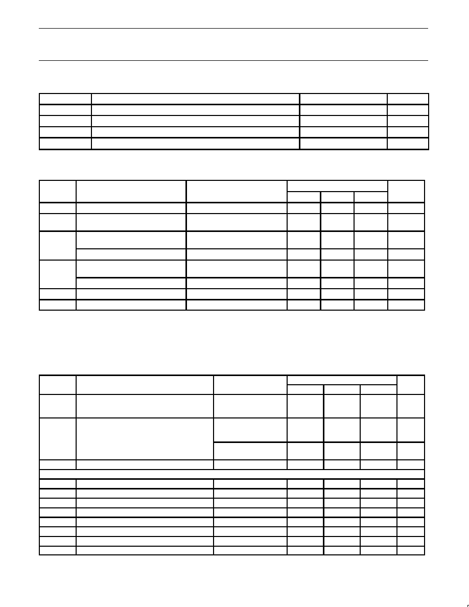
BLOCK DIAGRAM
NOISE
COMPANDOR
CANCEL
EXPANDOR
BANDGAP
VOLTAGE REF
VOX
SA5752
BUFFER
PREAMP
12
11
20
19
18
17
16
15
14
13
10
9
8
7
6
5
4
3
2
1
SR00660
Figure 2. Block Diagram
Philips Semiconductors
Product specification
SA5752
Audio processor ≠ companding, VOX and amplifier section
1997 Nov 07
4
ABSOLUTE MAXIMUM RATINGS
SYMBOL
PARAMETER
RATING
UNIT
V
CC
Power supply voltage range
-0.3 to 6
V
V
IN
Voltage applied to any other pin
-0.3 to (V
CC
+0.3)
V
T
STG
Storage temperature
-65 to +150
o
C
T
A
Ambient operating temperature
-40 to +85
∞
C
DC ELECTRICAL CHARACTERISTICS
T
A
= 25
o
C, V
CC
= +3.0V, 0dB = 77.5mV
RMS
. See test circuit, Figure 6.
SYMBOL
PARAMETER
TEST CONDITIONS
LIMITS
UNIT
SYMBOL
PARAMETER
TEST CONDITIONS
MIN
TYP
MAX
UNIT
V
CC
Supply voltage
2.7
4
3.0
5.5
V
I
CC
Supply current
No signal
Power down mode
3.1
125
4.0
mA
µ
A
Z
L
Load impedance
pins NCAN
OUT
, EXP
OUT
50
k
COMP
OUT
1
10
k
Z
IN
Input impedance
COMP
IN
, MIC
IN
40
50
60
k
EXP
IN
2
2.0
k
Noise cancellation current
Pin 6
25
µ
A
V
OS
DC offset NCAN
OUT
3
-50
≠3.0
50
mV
NOTES:
1. Compressor is tested in production with 50k
load.
2. Not tested in production.
3. Offset values are identical for both gain states of noise reduction circuit.
4. Operational down to V
CC
= 2V.
AC ELECTRICAL CHARACTERISTICS
T
A
= 25
o
C, V
CC
= +3.0V, 0dB level = 77.5mV
RMS
. See test circuit, Figure 6.
SYMBOL
PARAMETER
TEST CONDITIONS
LIMITS
UNIT
SYMBOL
PARAMETER
TEST CONDITIONS
MIN
TYP
MAX
UNIT
Preamplifier gain range
Preamplifier voltage gain 0dB
Preamplifier voltage gain 40dB
Pin 2 open
Pin 2 AC ground
0
-1.0
39.0
0
40
40
1.0
41.0
dB
dB
dB
Preamplifier noise density
Pin 2 AC grounded
RS = 50k
unweighted 20Hz-20kHz
7
nV/
Hz
weighted CCIR
DIN45405 20-20kHz
8
nV/
Hz
Switch amplifier gain
9
10
11
dB
Compandor 1kHz, all tests
1
COMP
OUT
Compressor error at -21dB output level
Input level = -42dB
≠1.0
≠0.16
1.0
dB
COMP
OUT
Compressor error at -10dB output level
Input level = -20dB
-1.0
≠0.11
1.0
dB
COMP
OUT
Compressor error at 0dB output level
Input level = 0dB
-1.5
+0.1
1.5
dB
COMP
OUT
Compressor error at +5dB output level
Input level = +10dB
-1.0
+0.04
1.0
dB
COMP
OUT
Compressor error at +10dB output level
Input level = +20dB
-1.0
+0.02
1.0
dB
EXP
OUT
Expandor error at -42dB output level
Input level = -21dB
≠1.0
≠0.12
1.0
dB
EXP
OUT
Expandor error at -21dB output level
Input level = -10.5dB
-1.0
+0.1
1.0
dB
EXP
OUT
Expandor error at -10dB output level
Input level = -5dB
-1.0
+0.03
1.0
dB

Philips Semiconductors
Product specification
SA5752
Audio processor ≠ companding, VOX and amplifier section
1997 Nov 07
5
AC ELECTRICAL CHARACTERISTICS
(Contineud)
SYMBOL
PARAMETER
TEST CONDITIONS
LIMITS
UNIT
SYMBOL
PARAMETER
TEST CONDITIONS
MIN
TYP
MAX
UNIT
EXP
OUT
Expandor error at 0dB output level
Input level = 0dB
-1.5
≠0.2
1.5
dB
EXP
OUT
Expandor error at +10dB output level
Input level = +5dB
-1.0
+0.03
1.0
dB
EXP
OUT
Expandor error at +20dB output level
2
Input level = +10dB
-1.0
≠0.1
1.0
dB
EXP
OUT
Expandor V
OS
No signal
-50.0
+3.0
50.0
mV
EXP
OUT
Expandor output DC shift
No signal to 0dB
-100
+2.0
100
mV
Timing capacitors compandor
2200
nF
THD
Total harmonic distortion
Compressor
1kHz, 0dB
BW=300-3kHz
0.2
1
%
Expandor
1kHz, 0dB
BW=300-3kHz
0.1
1
%
NCAN
OUT
1kHz. Pin 2 open
output level = 0dB
0.02
1
%
1kHz, Pin 2 open
output level = +20dB
0.06
1
%
VOX
OUT
Sink current
0.5
mA
Low level
High level
Open collector I
L
=
0.5mA
V
CC
0.4
V
V
VOX
CTL
Input current
Low
-50
≠6.6
0
µ
A
High
-10
≠0.02
+10
µ
A
Input level
Low
High
0
0.7V
CC
0.3V
CC
V
CC
V
V
H
PDN
Input current
Low
-10
≠4.1
+10
µ
A
High
-10
≠0.2
+10
µ
A
Input level
Low
High
0
0.7V
CC
0.3V
CC
V
CC
V
V
Reference filter capacitor
10
µ
F
NOTE:
1. Measurements are relative to 0dB output.
2. Measurement is indicative of the output dynamic range capability.
Philips Semiconductors
Product specification
SA5752
Audio processor ≠ companding, VOX and amplifier section
1997 Nov 07
6
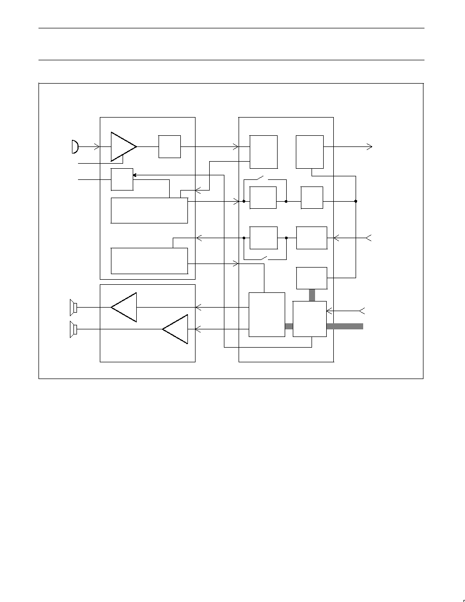
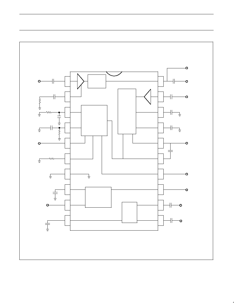
SA5753
SA5752
PREAMP
NOISE
CANCEL
VOX
COMPRESSOR
PA
PA
HEADPHONE
SPEAKER
VOX
OUTPUT
MICROPHONE
GAIN
CONTROL
TX
LOW
PASS
FILTER
TX
BANDPASS
FILTER
SUMMING
AMP
RX
DE≠
EMPHASIS
RX
BANDPASS
FILTER
DTMF
GENERATOR
ATTENUATOR
TX
PRE≠
EMPHASIS
I2C
BUS
INTERFACE
Companding and Amplifier Section
Filter and Control Section
AUDIO TO
TRANSMITTER
AUDIO FROM
RECEIVER
FROM SYSTEM
CONTROLLER I C BUS
2
DEMODULATOR
VOX CONTROL
EXPANDOR
TDA7050T
CLOCK
1.2MHz
SR00661
Figure 3. Typical Configuration of Audio Processor (APROC) System Chip Set

Philips Semiconductors
Product specification
SA5752
Audio processor ≠ companding, VOX and amplifier section
1997 Nov 07
7
5V
7.5V
5.0/0V
7.5/0V
POWER SUPPLY
DATA PROCESSOR
DATA BLOCK
RF BLOCK
AUDIO BLOCK
LOGIC UNIT
CONTROL UNIT
POWER SUPPLY ENABLE
SPEAKER
MIC
EAR
MOD
VOX
DEMOD
DATA
TXEN
DEMOD DATA
RXCLOCK
RXDATA
TXCLOCK
TXDATA
DCLOCK
DA
T
A
IN
SER
V
FVC
WSYNC
BUSY
I2C
8
SR00653
Figure 4. Cellular Radio System
5V
7.5V
5.0/0V
7.5/0V
POWER SUPPLY
DATA PROCESSOR
RF BLOCK
NE5750
LOGIC UNIT
CONTROL UNIT
POWER SUPPLY ENABLE
SPEAKER
MIC
EAR
MOD
VOX
DEMOD
DATA
TXEN
DEMOD DATA
8
I2C
RSSI
NE5751
SR00654
Figure 5. APROC Application Diagram
Philips Semiconductors
Product specification
SA5752
Audio processor ≠ companding, VOX and amplifier section
1997 Nov 07
8
1
2
3
4
5
6
7
8
9
10
19
18
16
15
14
13
12
11
PREAMPGRES
MICIN
20
17
VOX
NOISE
CANCEL
COMPRESSOR
BUFFER
BANDGAP
VOLTAGE REF
EXPANDOR
PREAMP
+
+
+
+
+
RECTGRES
NCANCAP
VOXOUT
VOXTR
GND
VREF
VCC
EXPCAP
EXPOUT
EXPIN
HPDN
VOXCTL
COMPCAP2
COMPOUT
COMPCAP1
COMPCAP3
COMPIN
NCANOUT
SIDE TONE
Avset
220nF
220nF
220nF
2.2
µ
F
2.2
µ
F
1
µ
F
4.7
µ
F
+
+
10
µ
F
2.2
µ
F
220nF
220nF
220nF
2.2
µ
F
39.2k
130k
11.2k
+
SR00662
Figure 6. SA5752 Test and Application Circuit
Philips Semiconductors
Product specification
SA5752
Audio processor ≠ companding, VOX and amplifier section
1997 Nov 07
9
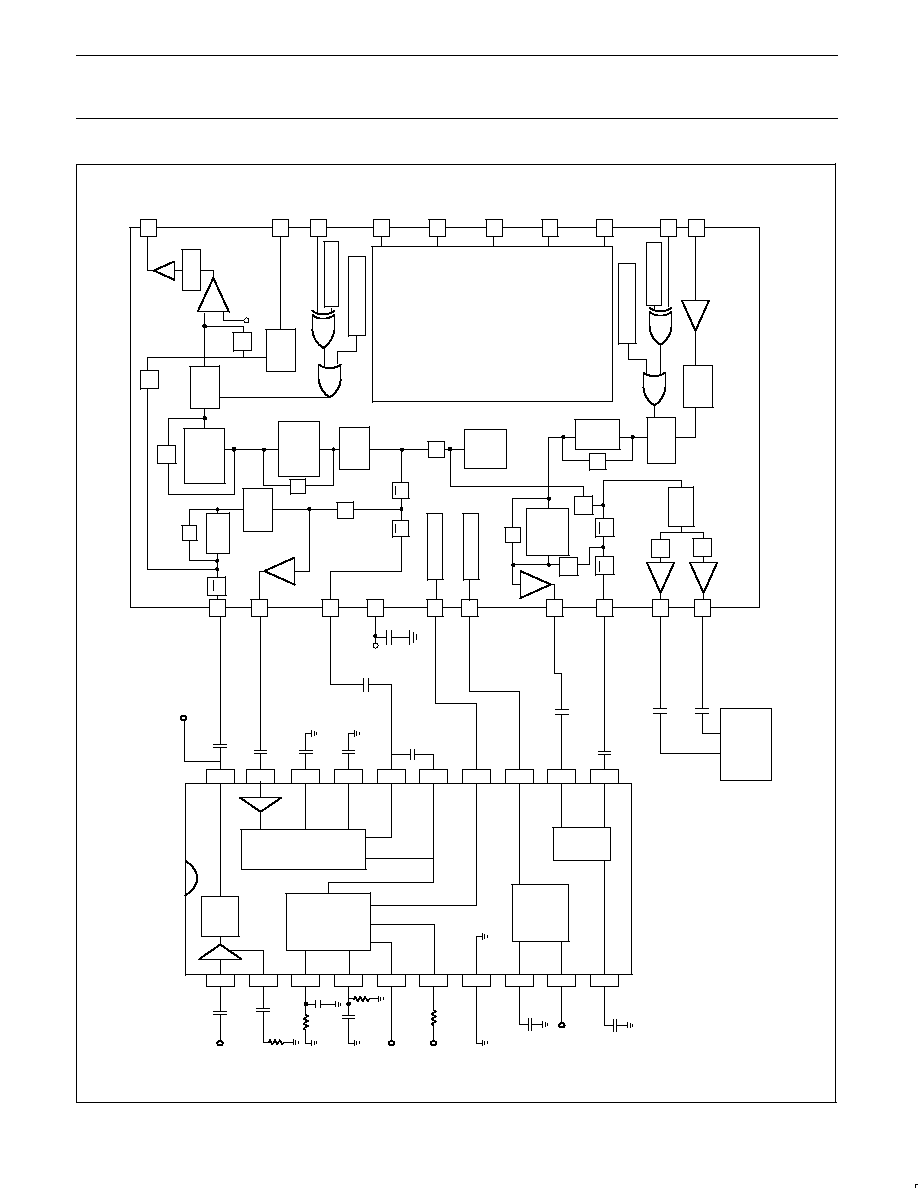
TXBPF OUT
PRE EMPH IN
DE EMPH OUT
VOX
TDA7050T
220nF
C10
C8
C16
C15
33nF
1
2
3
4
5
6
7
8
9
10
19
18
16
15
14
13
12
11
20
17
VOX
NOISE
CANCEL
COMP
BUFFER
BANDGAP
VOL
T
AGE
EXP
PREAMP
+
+
+
+
C1
C2
R1
A
vset
R2
39.2k
C3
220nF
C4
R3
130k
C5
220nF
C14
C13
220nF
C12
C1
1
C9
C7
MIC
REF
IN
PREAMP
GRES
RECT
GRES
NCAN
CAP
VOX
OUT
VOX
TR
GND
V
REF
EXP
CAP
NCAN
OUT
COMP
IN
COMP
CAP3
COMP
CAP1
COMP
OUT
COMP
CAP2
VOX
CTL
HPDN
EXP
IN
EXP
OUT
V
CC
R4
1
1.2k
C6
+
4.7 F
µ
10 F
µ
2.2 F
µ
220nF
2.2 F
µ
2.2 F
µ
220nF
220nF
SIDE T
ONE
220nF
2.2 F
µ
1 F
µ
6
7
8
9
10
4
20
19
18
17
16
15
14
13
12
11
S1
S2
S3
S2
S4
S5
S6
S7
S7
S9
S10
GND
SDA
SCL
TXBPF
TXLPF
A
TTN 1
A
TTN 2
MUTE
TX
A
TTN 3
PREEMPH
AND
SOFT LIM
DTMF GEN
DEEMPH
A
TTN 4
I2C R5B1
I2C R8B7
I2C R8B1
RXBPF
Tx MUTE R0B4
MUTE
RX
Rx MUTE R0B5
I2C R8B3
A
TTN 7
S12
S12
A
TTN 6
S13
S1
1
TX
OUT
DA
T
A
IN
TX
MUTE
1.2MHz
CLOCK
IN
DFT
RX
MUTE
RX DEMOD
IN
3
5
1
2
I C INTERF
ACE
AND
REGISTERS
2
V
REF
TXBPF IN
V
DD
HPDN
AUDIO IN
SPKR OUT
EAR OUT
CTL
SA5752
SA5753
S4
S8
+
+
0.1 F
µ
S8
SR00663
Figure 7. Application Diagram for the Audio Processor

Philips Semiconductors
Product specification
SA5752
Audio processor ≠ companding, VOX and amplifier section
1997 Nov 07
10
TYPICAL PERFORMANCE CHARACTERISTICS
EXPANDOR
COMPRESSOR
THD vs Temperature for 3V Supply
THD (%)
1.0
0.9
0.8
0.7
0.6
0.5
0.4
0.3
0.2
0.1
0.0
≠50 ≠40 ≠30 ≠20 ≠10 0
10
20
30
40
50
60
70
80
90
100
TEMPERATURE (
∞
C)
SUPPL
Y
CURRENT
(mA)
4.00
3.75
3.50
3.25
3.00
2.75
2.50
2.25
2.00
≠50 ≠40 ≠30 ≠20 ≠10 0
10
20
30
40
50
60
70
80
90
100
TEMPERATURE (
∞
C)
VCC = 3V
Supply Current vs Temperature and Supply Voltage
Power Down Supply Current vs
Temperature and Supply Voltage
TEMPERATURE (
∞
C)
POWER DOWN SUPPL
Y
CURRENT
(mA)
0.40
0.35
0.30
0.25
0.20
0.15
0.10
0.05
0.00
≠50 ≠40 ≠30 ≠20 ≠10 0
10
20
30
40
50
60
70
80
90
100
EXPANDOR
COMPRESSOR
Compandor Tracking Error vs Input Level
OUTPUT ERROR (dB)
1.0
0.8
0.6
0.4
0.2
0.0
≠0.2
≠0.4
≠0.6
≠0.8
≠1.0
≠45 ≠40 ≠35 ≠30 ≠25 ≠20 ≠15 ≠10 ≠5
0
5
10
15
20
25
INPUT LEVEL (dB)
Unity Gain Error vs Temperature
TEMPERATURE (
∞
C)
UNITY GAIN ERROR (dB)
≠50 ≠40 ≠30 ≠20 ≠10 0
10
20
30
40
50
60
70
80
90
100
SUPPLY VOLTAGE (V)
UNITY GAIN ERROR (dB)
1.5
1.25
1.00
0.75
0.50
0.25
0.00
≠0.25
≠0.50
≠0.75
≠1.00
≠1.25
≠1.50
1.5
2.0
2.5
3.0
3.5
4.0
4.5
5.0
5.5
6.0
Unity Gain Error vs Supply Voltage
VCC = 5.5V
VCC = 2.7V
VCC = 2V
EXPANDOR
COMPRESSOR
COMPRESSOR
EXPANDOR
VCC = 3V
VCC = 5.5V
VCC = 2.7V
VCC = 2V
1.5
1.25
1.00
0.75
0.50
0.25
0.00
≠0.25
≠0.50
≠0.75
≠1.00
≠1.25
≠1.50
SR00664
Figure 8. Typical Performance Characteristics
Philips Semiconductors
Product specification
SA5752
Audio processor ≠ companding, VOX and amplifier section
1997 Nov 07
11
TYPICAL PERFORMANCE CHARACTERISTICS
(Continued)
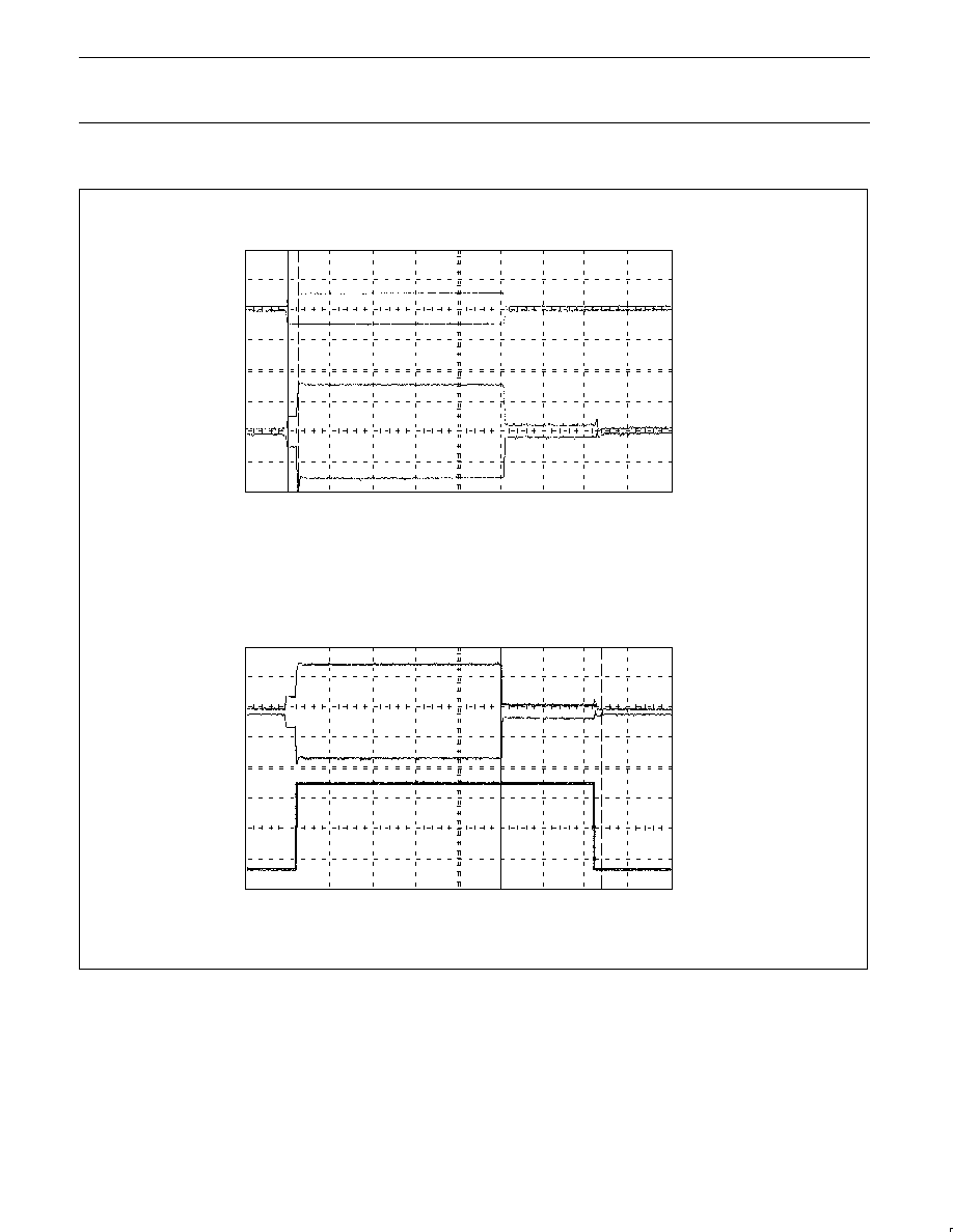
Noise Cancellation Switching Amplifier
DYNAMIC RESPSONSE
Voice Activated Transmitter (VOX)
DYNAMIC RESPSONSE
1
4
1
3
MICIN
NCANOUT
30.0mV/div
30.0mV/div
30.0mV/div
1.00V/div
NCANOUT
VOXOUT
VOXCTL
PIN 1
PIN 20
PIN 20
PIN 5
= LOW
50.0ms/div
50.0ms/div
STOP MARKER:
START MARKER:
t:
11.960 ms
0.00000 s
11.960 ms
STOP MARKER:
START MARKER:
t:
120.000 ms
0.00000 s
120.000 ms
SR00665
Figure 9. Typical Performance Characteristics (cont.)

Philips Semiconductors
Product specification
SA5752
Audio processor -- companding, VOX and amplifier section
1997 Nov 07
12
SSOP20:
plastic shrink small outline package; 20 leads; body width 4.4 mm
SOT266-1
Philips Semiconductors
Product specification
SA5752
Audio processor -- companding, VOX and amplifier section
1997 Nov 07
13
Philips Semiconductors and Philips Electronics North America Corporation reserve the right to make changes, without notice, in the products,
including circuits, standard cells, and/or software, described or contained herein in order to improve design and/or performance. Philips
Semiconductors assumes no responsibility or liability for the use of any of these products, conveys no license or title under any patent, copyright,
or mask work right to these products, and makes no representations or warranties that these products are free from patent, copyright, or mask
work right infringement, unless otherwise specified. Applications that are described herein for any of these products are for illustrative purposes
only. Philips Semiconductors makes no representation or warranty that such applications will be suitable for the specified use without further testing
or modification.
LIFE SUPPORT APPLICATIONS
Philips Semiconductors and Philips Electronics North America Corporation Products are not designed for use in life support appliances, devices,
or systems where malfunction of a Philips Semiconductors and Philips Electronics North America Corporation Product can reasonably be expected
to result in a personal injury. Philips Semiconductors and Philips Electronics North America Corporation customers using or selling Philips
Semiconductors and Philips Electronics North America Corporation Products for use in such applications do so at their own risk and agree to fully
indemnify Philips Semiconductors and Philips Electronics North America Corporation for any damages resulting from such improper use or sale.
This data sheet contains preliminary data, and supplementary data will be published at a later date. Philips
Semiconductors reserves the right to make changes at any time without notice in order to improve design
and supply the best possible product.
Philips Semiconductors
811 East Arques Avenue
P.O. Box 3409
Sunnyvale, California 94088≠3409
Telephone 800-234-7381
DEFINITIONS
Data Sheet Identification
Product Status
Definition
Objective Specification
Preliminary Specification
Product Specification
Formative or in Design
Preproduction Product
Full Production
This data sheet contains the design target or goal specifications for product development. Specifications
may change in any manner without notice.
This data sheet contains Final Specifications. Philips Semiconductors reserves the right to make changes
at any time without notice, in order to improve design and supply the best possible product.
©
Copyright Philips Electronics North America Corporation 1997
All rights reserved. Printed in U.S.A.
Philips
Semiconductors