DATA SHEET
Product specification
File under Integrated Circuits, IC01
June 1989
INTEGRATED CIRCUITS
SAA3010
Infrared remote control transmitter
RC-5

June 1989
2
Philips Semiconductors
Product specification
Infrared remote control transmitter RC-5
SAA3010
FEATURES
∑
Low voltage requirement
∑
Biphase transmission technique
∑
Single pin oscillator
∑
Test mode facility
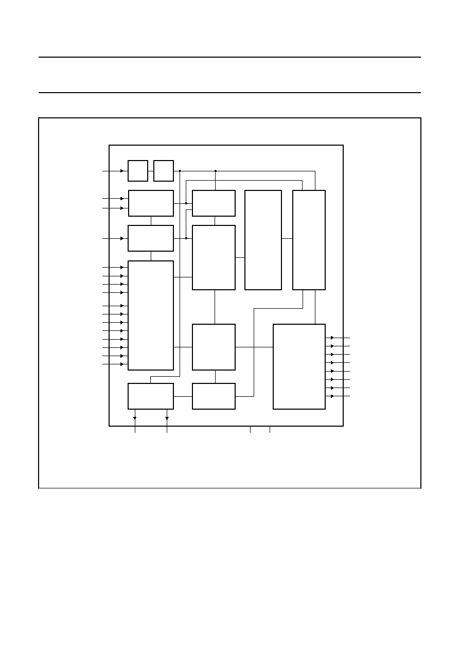
GENERAL DESCRIPTION
The SAA3010 is intended as a general purpose (RC-5)
infrared remote control system for use where a low voltage
supply and a large debounce time are expected.
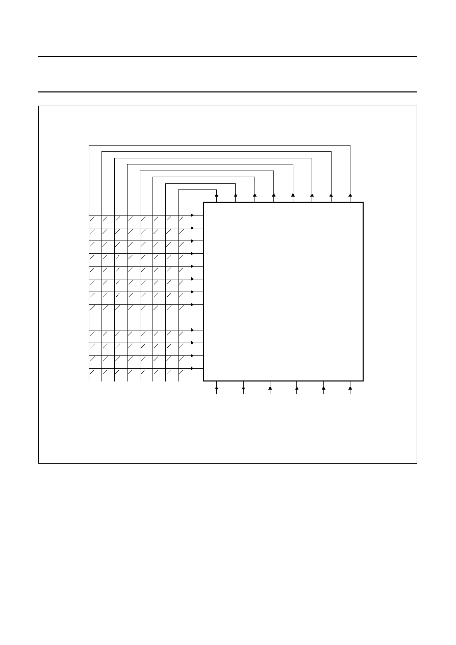
The device can generate 2048 different commands and
utilizes a keyboard with a single pole switch for each key.
The commands are arranged so that 32 systems can be
addressed, each system containing 64 different
commands. The keyboard interconnection is illustrated by
Fig.3.
The circuit response to legal (one key pressed at a time)
and illegal (more than one key pressed at a time) keyboard
operation is specified in the section "Keyboard operation".
QUICK REFERENCE DATA
Note
1. V
DD
+0.5 V must not exceed 9 V.
PACKAGE OUTLINES
28-lead DIL plastic; (SOT117); SOT117-1; 1996 September 11.
28-lead mini-pack; plastic (SO28; SOT136A); SOT136-1; 1996 September 11.
PARAMETER
SYMBOL
MIN.
TYP.
MAX.
UNIT
Supply voltage range
V
DD
2
-
7
V
Input voltage range (note 1)
V
I
-
0.5
-
V
DD
+0.5
V
Input current
I
I
-
-
±
10
mA
Output voltage range (note 1)
V
O
-
0.5
-
V
DD
+0.5
V
Output current
I
O
-
-
±
10
mA
Operating ambient temperature
range
T
amb
-
25
-
85
∞
C
WARNING
The use of this device must conform with the Philips Standard number URT-0421.
June 1989
4
Philips Semiconductors
Product specification
Infrared remote control transmitter RC-5
SAA3010
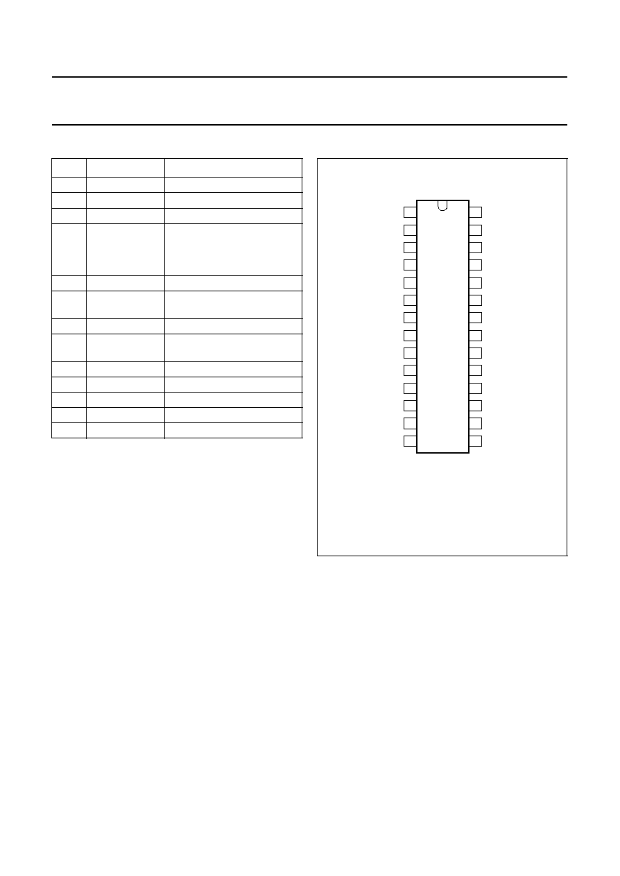
PINNING
Note
1. (I) = input
(IPU) = input with p-channel pull-up transistor
(ODN) = output with open drain n-channel transistor
(OP3) = output 3-state
PIN
MNEMONIC
(1)
FUNCTION
1
X7 (IPU)
sense input from key matrix
2
SSM (I)
system mode selection input
3-6
Z0-Z3 (IPU)
sense inputs from key matrix
7
MDATA (OP3)
generated output data
modulated with 1/12 the
oscillator frequency at a 25%
duty factor
8
DATA (OP3)
generated output information
9-13
DR7-DR3
(ODN)
scan drivers
14
V
SS
ground (0 V)
15-17
DR2-DR0
(ODN)
scan drivers
18
OSC (I)
oscillator input
19
TP2 (I)
test point 2
20
TP1 (I)
test point 1
21-27
X0-X6 (IPU)
sense inputs from key matrix
28
V
DD
(I)
voltage supply
handbook, halfpage
X7
SSM
Z0
Z1
Z2
Z3
MDATA
DATA
DR7
DR6
DR5
DR4
DR3
VSS
VDD
X6
X5
X4
X2
X1
X3
X0
TP1
TP2
OSC
DR0
DR1
DR2
1
2
3
4
5
6
7
8
9
10
11
12
13
28
27
26
25
24
23
22
21
20
19
18
17
16
15
14
SAA3010
MGE346
Fig.2 Pinning diagram.