 | –≠–ª–µ–∫—Ç—Ä–æ–Ω–Ω—ã–π –∫–æ–º–ø–æ–Ω–µ–Ω—Ç: SAA7240 | –°–∫–∞—á–∞—Ç—å:  PDF PDF  ZIP ZIP |
Document Outline
- 1 FEATURES
- 1.1 General
- 1.2 External interfaces
- 1.3 CPU-related features
- 1.4 MPEG-2 System Processor (MSP) features
- 1.5 Compatibility with other devices
- 2 GENERAL DESCRIPTION
- 2.1 Limitation notes
- 2.2 Integrated Conditional Access Module (ICAM Æ ) licensing requirements
- 3 ORDERING INFORMATION
- 4 BLOCK DIAGRAMS
- 5 PINNING INFORMATION
- 5.1 Pinning
- 5.2 Pin description
- 5.3 Pin list in numerical order
- 6 LIMITING VALUES
- 7 HANDLING
- 8 THERMAL CHARACTERISTICS
- 9 DC CHARACTERISTICS
- 9.1 Power saving in Sleep and Coma modes
- 9.2 Maximum allowable load capacitance on output pins
- 10 APPLICATION INFORMATION
- 10.1 Application examples of the multi-master mode
- 10.2 Memory configurations
- 11 PACKAGE OUTLINE
- 12 SOLDERING
- 12.1 Introduction to soldering surface mount packages
- 12.2 Reflow soldering
- 12.3 Wave soldering
- 12.4 Manual soldering
- 12.5 Suitability of surface mount IC packages for wave and reflow soldering methods
- 13 DATA SHEET STATUS
- 14 DEFINITIONS
- 15 DISCLAIMERS
- 16 PURCHASE OF PHILIPS I2C COMPONENTS
DATA SHEET
Product specification
File under Integrated Circuits, IC02
2001 Oct 22
INTEGRATED CIRCUITS
SAA7240
MPEG-2 Transport RISC processor

2001 Oct 22
2
Philips Semiconductors
Product specification
MPEG-2 Transport RISC processor
SAA7240
CONTENTS
1
FEATURES
1.1
General
1.2
External interfaces
1.3
CPU-related features
1.4
MPEG-2 System Processor (MSP) features
1.5
Compatibility with other devices
2
GENERAL DESCRIPTION
2.1
Limitation notes
2.2
Integrated Conditional Access Module (ICAM
Æ
)
licensing requirements
3
ORDERING INFORMATION
4
BLOCK DIAGRAMS
5
PINNING INFORMATION
5.1
Pinning
5.2
Pin description
5.3
Pin list in numerical order
6
LIMITING VALUES
7
HANDLING
8
THERMAL CHARACTERISTICS
9
DC CHARACTERISTICS
9.1
Power saving in Sleep and Coma modes
9.2
Maximum allowable load capacitance on
output pins
10
APPLICATION INFORMATION
10.1
Application examples of the multi-master mode
10.2
Memory configurations
11
PACKAGE OUTLINE
12
SOLDERING
12.1
Introduction to soldering surface mount
packages
12.2
Reflow soldering
12.3
Wave soldering
12.4
Manual soldering
12.5
Suitability of surface mount IC packages for
wave and reflow soldering methods
13
DATA SHEET STATUS
14
DEFINITIONS
15
DISCLAIMERS
16
PURCHASE OF PHILIPS I
2
C COMPONENTS

2001 Oct 22
3
Philips Semiconductors
Product specification
MPEG-2 Transport RISC processor
SAA7240
1
FEATURES
1.1
General
∑
Conditional access descrambling Digital Video
Broadcasting (DVB) compliant, MULTI2 compliant and
ICAM
Æ
(1)
compliant
∑
Targeted to BSkyB 3.00 and Canal
+
basic box 3.02 and
web box 1.01 applications
∑
Stream demultiplexing: Transport Stream (TS),
Packetized Elementary Stream (PES), Program Stream
(PS) and Proprietary data streams
∑
Internal 32-bit MIPS RISC-based CPU, supporting
MIPS16 instruction set and running at 81 MHz
∑
Low-power Sleep modes supported across the chip
∑
Support for external co-processor
∑
0.25
µ
m technology
∑
Power supply of 2.5 V for the core and 3.3 V for the
peripherals, to be TTL level compatible
∑
Comprehensive driver software and development tool
support
∑
Package: SQFP208.
1.2
External interfaces
The SAA7240 supports the following external interfaces:
∑
Versatile transport stream input/output at 13.5 Mbytes/s
configurable in parallel or serial mode. Interfaces to
IEEE 1394 devices (such as Philips PDI 1394 chip-set)
in full-duplex mode and to external descramblers
through a Common Interface (CI) device. The following
interfaces are supported:
≠ 3 parallel TS input/output ports
≠ 2 parallel TS input/output ports and 3 serial TS ports
≠ 1 parallel TS input/output port and 5 serial TS ports
≠ 6 serial TS input/output ports.
∑
A microcontroller extension bus, supporting:
≠ 16-bit and 32-bit data buses
≠ Up to 64 Mbytes addressing range
≠ Synchronous Dynamic RAM (SDRAM) interface
≠ Dynamic RAM interface
≠ Read Only Memory (ROM) interface
≠ Flash memory interface
≠ Interface to various peripherals
≠ Synchronous interface to communicate with the
integrated MPEG Audio Video Graphics Decoder
(AVGD) SAA7215 at 40.5 MHz
≠ Large endian and small endian byte addressing
≠ A multi-master mode (master and slave modes).
∑
2-channel Direct Memory Access (DMA) for fast block
move to/from any memory location
∑
Up to 12 chip selects available, some can be configured
as general purpose ports
∑
An IEEE 1284 interface (Centronics) with DMA engine
supporting master and slave modes. Usable as a
general purpose port
∑
Two UART (RS232) data ports with DMA capabilities (at
187.5 kbit/s), including hardware flow control signals
RXD, TXD, RTS and CTS for modem support
∑
A Synchronous Serial Interface (SSI) to connect an
off-chip modem analog front-end
∑
An elementary UART with DMA capabilities, dedicated
to front panel devices for instance
∑
Two dedicated smart card reader interfaces (ISO 7816
compatible) with DMA capabilities. One interface is
intended for the conditional access and is shared with
the Integrated Conditional Access Module (ICAM) when
ICAM is enabled; the second interface may be used for
pay-per-view
∑
Two I
2
C-bus master/slave transceivers with DMA
capabilities, supporting the standard (100 kbit/s) and
fast (400 kbit/s) I
2
C-bus modes
∑
32-bit general purpose port
∑
Eight interrupt inputs
∑
Parallel audio video interface to the MPEG AVGD
decoder SAA7215
∑
One Pulse Width Modulated (PWM) output with 8-bit
resolution
∑
An Extended JTAG (EJTAG) interface for board test
support.
(1)
Integrated Conditional Access Module (
ICAM
Æ
) is an
intellectual property of News Data System
Corporation.

2001 Oct 22
4
Philips Semiconductors
Product specification
MPEG-2 Transport RISC processor
SAA7240
1.3
CPU-related features
The SAA7240 contains an embedded RISC CPU, which
incorporates the following features:
∑
A 32-bit PR3930 core, running at 81 MHz
∑
Support for large and small byte addressing modes; is
ready for Windows
Æ
(1)
CE and pSOS
Æ
(2)
operating
systems
∑
8-kbyte 2-way set of associative instruction cache
∑
4-kbyte 4-way set of associative data cache
∑
A programmable low-power mode, including wake-up
on interrupt
∑
A Memory Management Unit (MMU) with 32 odd/even
entries and variable page sizes
∑
Multiply/accumulate/divide unit with fast
multiply/accumulate for 16-bit and 32-bit operands
∑
Two fully independent 24-bit timers and one 24-bit timer,
including watchdog facilities
∑
A real-time clock unit (active in Sleep mode)
∑
Built-in software debug support unit as part of extended
JTAG debug interface
∑
On-chip SRAM of 4 kbytes for storing code that needs
fast execution.
1.4
MPEG-2 System Processor (MSP) features
∑
A flexible re-router to support many combinations of the
transport stream input/output interfaces:
≠ Connection to serial or parallel Common Interface IC
≠ Connection to serial or parallel 1394 IC in full-duplex
mode
≠ Static dual front-end handling of channel decoders
≠ A maximum frequency of up to 13.5 Mbytes/s in
parallel mode and up to 81 Mbits/s in serial mode.
∑
A demultiplexer scheme, which is fully compliant with
Canal
+
and BSkyB specifications:
≠ Hardware-based parsing of transport, program and
proprietary software data streams. The maximum
input rate is 13.5 Mbytes/s in parallel mode and
81 Mbits/s in serial mode
≠ Up to 40, 13-bit Packet Identifier (PID) filters applied
on the PID value. 32 PID filters can be dedicated to
filter packets containing sections; four PID filters to
filter transport packets header; four PID filters to
parse audio, video, teletext and subtitle data
≠ 4 TS/PES packet header filters (filter condition of
3 bytes, including PID value for TS packet header
and specific filter condition for PES packet header)
≠ 32 section filters based on a flexible number of filter
conditions to retrieve PSI, SI, Private data and EPG,
etc. Each section filter supports 48 filters conditions
of 12 bytes; each filter condition can be negated or
masked on a bit level
≠ 7 ECM/EMM filters stored in on-chip RAM for ICAM
implementation (ECM/EMM packets are stored in
on-chip RAM)
≠ Flexible 40 channel DMA-based storage of the
32 section sub-streams and four TS/PES data
sub-streams and 4 TS/PES packet headers in
external memory
≠ System time base management with a double
counter mechanism for clock control and
discontinuity handling
≠ Two Presentation Time Stamp (PTS)/Decoding Time
Stamp (DTS) timers
≠ A General Purpose/High Speed (GP/HS) filter, which
can serve as an alternative input from IEEE 1394
devices, for example. The IEEE 1394 GP/HS mode
supports packet insertion and has an internal SRAM
for storing two packets. It can also output either
scrambled or descrambled TS to IEEE 1394 devices.
∑
A real time descrambler, supporting different
descrambler algorithms and consisting of four modules:
≠ A control word bank, containing 14 pairs (odd or
even) of control words and a default control word
≠ The DVB descrambler core, implementing the stream
decipher and block decipher algorithms
≠ The MULTI2 descrambler algorithm, implementing
the CBC and OFB mode descrambling functions.
In this mode, the maximum frequency is 9 Mbytes/s
(72 Mbits/s)
≠ The Integrated Conditional Access Module (ICAM),
including an ISO 7816 compliant UART to interface
the conditional access smart card.
1.5
Compatibility with other devices
The SAA7240 seamlessly interfaces to the integrated
MPEG AVGD decoder SAA7215HS. It is also backward
compatible with the other devices of the family. The
following modes/combinations are supported:
∑
SAA7240 with SAA7215HS seamless
∑
Pinning compatibility with the SAA7219HS.
(1) Windows is a registered trademark of Microsoft Corporation
(2) pSOS is a registered trademark of Wind River Systems, Inc.

2001 Oct 22
5
Philips Semiconductors
Product specification
MPEG-2 Transport RISC processor
SAA7240
2
GENERAL DESCRIPTION
The SAA7240 is a transport MPEG-2 source decoder
designed for application in set-top boxes in a Digital Video
Broadcast (DVB) environment. It is targeted to BSkyB 3.00
and Canal
+
basic box and web box applications. The
device is part of a comprehensive source decoding kit that
contains all the hardware and software required to receive
and decode MPEG-2 transport streams, including
descrambling and demultiplexing.
In addition, it includes a PR3930 core, which is a 32-bit
MIPS RISC-based CPU core supporting the MIPS16
instruction set (to reduce memory requirements) and
several peripheral interfaces such as UARTs, I
2
C-bus
units, an IEC 1883, and an IEEE 1284 (Centronics)
interface. The SAA7240 is therefore capable of performing
all controller tasks in digital television applications.
Furthermore, the SAA7240 complies with DVB, ICAM and
MULTI2 descrambler standards.
The SAA7240 receives transport streams through a
versatile stream input interface capable of handling both
byte-parallel and bit-serial streams, in various formats,
supporting data streams up to and including 13.5 Mbytes/s
in parallel mode and 81 Mbits/s in serial mode. The data
stream is first applied to an on-chip descrambler with a
DVB descrambling algorithm, on the basis of 14 control
word pairs stored in an on-chip RAM.
Demultiplexing is subsequently applied to the data stream,
to separate up to 40 individual data streams. The
demultiplexer section includes clock recovery and
timebase management. Program Specific Information
(PSI), Service Information (SI), Conditional Access (CA)
messages and private data are selected and stored in
external memory, for subsequent off-line processing by
the internal PR3930 CPU core.
To support advanced board testing facilities, the SAA7240
includes Boundary Scan Test (BST) hardware, according
to the JTAG standard. The device features flexible
low-power Sleep modes, which independently control the
activity of each functional block and can sustain set-top
box standby functionality, thus eliminating the need for a
separate front-panel controller.
The SAA7240 requires a supply voltage of 3.3 V for the
I/O pads and a supply voltage of 2.5 V for the core.
2.1
Limitation notes
Although the most advanced techniques and sophisticated
tools are used during the design and validation phases,
some design limitations giving some restrictions for
specific applications might be discovered during the
characterization of the SAA7240 and during its life time.
If such an eventuality occurs, a limitation note will be
issued, describing the deviation against the specification
and the advised work-around if any. This limitation note,
also sometimes called `anomaly sheet' or `bug list', is given
to customers when they are in the initial design-in phase.
Once the design-in is in production phase, customers are
informed about any new limitation if the severity is
estimated to be high.
Please contact your nearest Philips Semiconductor sales
office for more information.
2.2
Integrated Conditional Access Module (ICAM
Æ
)
licensing requirements
Companies planning to use ICAM
Æ
implementation in any
final product must obtain a license from News Data
System Corporation before designing such products.
Additional per-chip royalties may be required and are to be
paid by the purchaser to News Data System Corporation.
For information on the Integrated Conditional Access
Module features, a non-disclosure agreement must be
signed with Philips Semiconductors to get the ICAM
Æ
specification.
Please contact your nearest Philips Semiconductor sales
office for more information.
3
ORDERING INFORMATION
TYPE NUMBER
PACKAGE
NAME
DESCRIPTION
VERSION
SAA7240
SQFP208
plastic shrink quad flat package, 208 leads (lead length 1.3 mm);
body 28
◊
28
◊
34 mm; high stand-off height
SOT316-1
2001
Oct
22
6
Philips Semiconductors
Product specification
MPEG-2 T
r
anspor
t RISC processor
SAA7240
This text is here in white to force landscape pages to be rotated correctly when browsing through the pdf in the Acrobat reader.This text is here in
_
white to force landscape pages to be rotated correctly when browsing through the pdf in the Acrobat reader.This text is here inThis text is here in
white to force landscape pages to be rotated correctly when browsing through the pdf in the Acrobat reader. white to force landscape pages to be ...
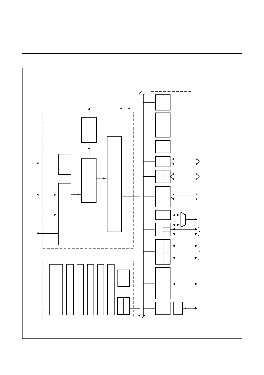
4
BLOCK DIA
GRAMS
u
ll pagewidth
FCE811
PI-BUS
CTRL
INPUT/OUTPUT ROUTER
MIPS
PR3930
CORE
DATA CACHE
INSTRUCTION CACHE
TIMER 1
TIMER 2
DSU
EJTAG
TIMER 3 (WATCHDOG)
AUDIO AND
VIDEO
INTERFACE
BUFFER POOL CONTROLLER
DEMUX AND
DESCRAMBLERS
MMU
PWM
RESETN
CLK
JTAG
Peripheral section
EXTENSION BUS
CONTROLLER AND
DMA
CARD READER
SAA7240
UART
0 1
0
1
0
S
M = master peripheral with embedded DMA channel
S = slave peripheral
S
M
M
PI-bus
M
S
M
M
M
CPU section
PWM
MSP section
(1)
S
S
S
1
2
PIO
INTERFACE
I
2
C-bus
IEEE
1284
SSI
RTC
32 kHz
INTERRUPT
CONTROLLER
4-KBYTE
SRAM
GPDATA
PKTDATA
GPD
IEEE 1284
interface
I
2
C-bus
interface
PIO
interface
UART
interface
AV PES
interface
extension
bus
smart card
interface
SSI
interface
EJTAG
interface
Fig.1 Block diagram.
(1) The MSP section is shown in more detail in Fig.2.
2001 Oct 22
7
Philips Semiconductors
Product specification
MPEG-2 Transport RISC processor
SAA7240
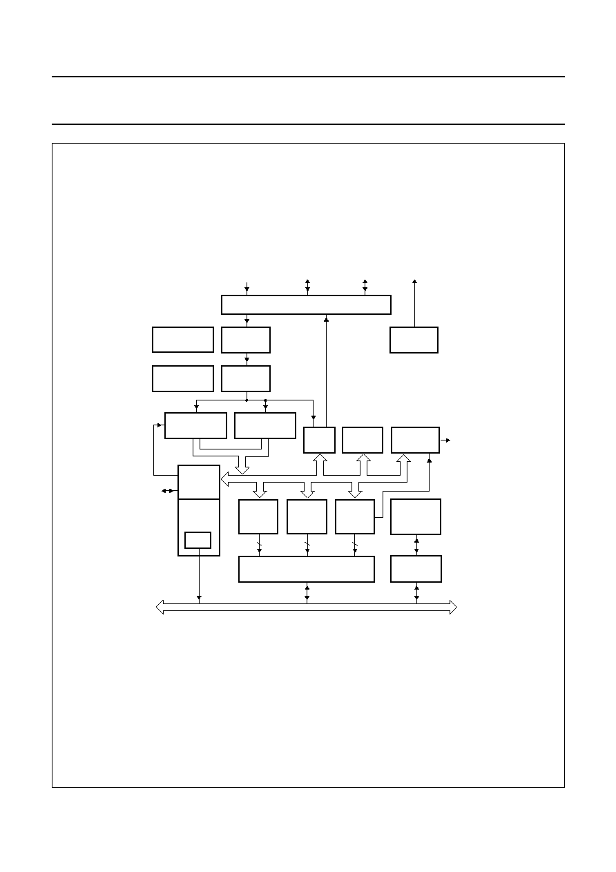
handbook, full pagewidth
BUFFER POOL CONTROLLER
WITH 40 DMA CHANNELS
SECTION
FILTER
PI-bus
FCE824
TS-PES
PACKET
FILTER
TS-PES
HEADER
FILTER
CONTROL &
STATUS
REGISTERS
PI
INTERFACE
AV
INTERFACE
PCR/SCR
GP/HS
MPEG bus
MULTI2
DESCRAMBLER
DVB
DESCRAMBLER
PID
FILTER
BIST
CONTROLLERS
INPUT
INTERFACE
PWM
INTERRUPT
HANDLER
ECM/EMM
FILTER
CA/UART
MODULE
smart
card
interface
AV PES
interface
RAM
4
4
32
INPUT / OUTPUT ROUTER
PKTDATA
TO / FROM SERIAL OR PARALLEL PORTS
GPD
PWM
GPDATA
Fig.2 MSP block diagram.
2001 Oct 22
8
Philips Semiconductors
Product specification
MPEG-2 Transport RISC processor
SAA7240
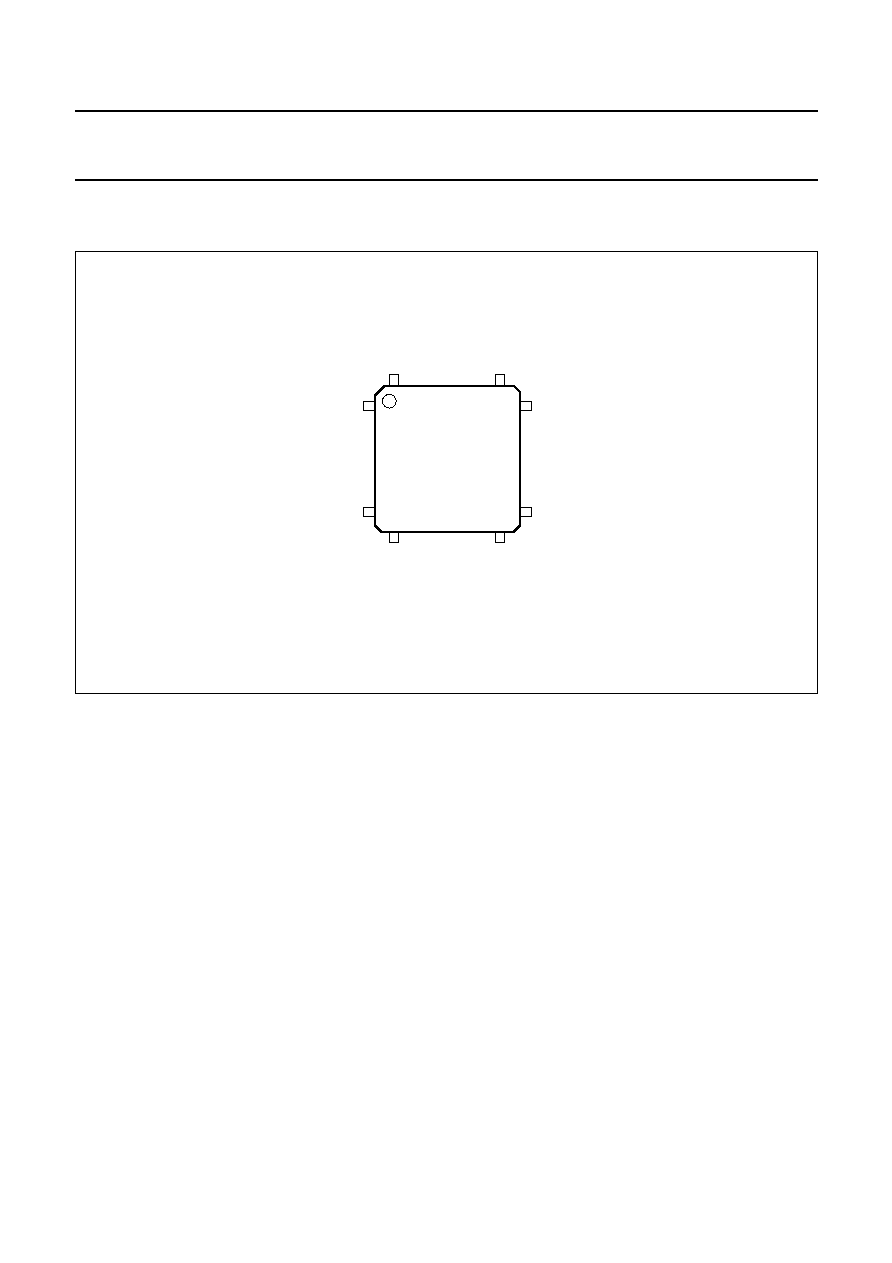
5
PINNING INFORMATION
5.1
Pinning
handbook, halfpage
SAA7240HS
1
208
157
53
104
52
156
105
FCE812
Fig.3 Pin configuration.

2001
Oct
22
9
Philips Semiconductors
Product specification
MPEG-2 T
r
anspor
t RISC processor
SAA7240
This text is here in white to force landscape pages to be rotated correctly when browsing through the pdf in the Acrobat reader.This text is here in
_
white to force landscape pages to be rotated correctly when browsing through the pdf in the Acrobat reader.This text is here inThis text is here in
white to force landscape pages to be rotated correctly when browsing through the pdf in the Acrobat reader. white to force landscape pages to be ...
5.2
Pin description
Table 1
Interface signal descriptions
SYMBOL
PIN
TYPE
DESCRIPTION
BUFFER TYPE
RESET
STATE
Programmable input/output port
PIO[0:7]/INT[0:7]
105 to 112
I/O
I/O lines or interrupt inputs
bidirectional; CMOS input; 2 mA
output drive
Z
PIO8
113
I/O
I/O line
bidirectional; CMOS input; 2 mA
output drive
Z
PIO9
114
I/O
I/O line
bidirectional; CMOS input; 2 mA
output drive
Z
PIO10/BPN
116
I/O
I/O line or bus pre-empt; this requires the bus owner to
release the bus after the current transfer
bidirectional; CMOS input; 2 mA
output drive
Z
PIO11/VPP
117
I/O
I/O line or VPP; control signal for the supply voltage
(ICAM)
bidirectional; CMOS input; 2 mA
output drive
Z
PIO12/C8
118
I/O
I/O line or IO data for conditional access (ICAM)
bidirectional; CMOS input;
8 mA output drive; open-drain;
Z
PIO13/C4
119
I/O
I/O line or IO data for conditional access (ICAM)
bidirectional; 8 mA output drive;
open-drain
Z
PIO14/BRN
120
I/O
I/O line or bus request input
bidirectional; CMOS input; 2 mA
output drive
Z
PIO15/BGN
121
I/O
I/O line or bus grant output
bidirectional; CMOS input; 2 mA
output drive
Z
PIO[16:31]/D[16:31]
20 to 11,
9 to 4, 2
I/O
I/O lines or upper data bus in 32-bit configuration
bidirectional; CMOS input;
3-state output; 2 mA output drive
Z
Extension bus interface
D[0:15]
41 to 28,
25 to 21
I/O
lower 16-bit data bus
bidirectional; CMOS input;
3-state output; 2 mA output drive
Z
A[0:21]
63 to 90
O
address bus
3-state output; 2 mA output drive
LOW
A[22:25]
(1)
n.a.
address bus extension shared with the IEEE 1284
interface
n.a.
n.a.
RAS0N
49
O
row access strobe for DRAM and SDRAM bank 0
3-state output; 2 mA output drive
HIGH
RAS1N/DCS1N
48
O
row access strobe for DRAM and SDRAM bank 1 or
SDRAM chip select bank 1
3-state output; 2 mA output drive
HIGH
LCASN/LBA#/SIZE0
46
O
column access strobe lower byte
3-state output; 2 mA output drive
HIGH

2001
Oct
22
10
Philips Semiconductors
Product specification
MPEG-2 T
r
anspor
t RISC processor
SAA7240
This text is here in white to force landscape pages to be rotated correctly when browsing through the pdf in the Acrobat reader.This text is here in
_
white to force landscape pages to be rotated correctly when browsing through the pdf in the Acrobat reader.This text is here inThis text is here in
white to force landscape pages to be rotated correctly when browsing through the pdf in the Acrobat reader. white to force landscape pages to be ...
MLCASN/BAA#/SIZE1
45
O
column access strobe mid lower byte
3-state output; 2 mA output drive
HIGH
MUCASN/SIZE2
44
O
column access strobe mid upper byte
3-state output; 2 mA output drive
HIGH
UCASN
42
O
column access strobe upper byte
3-state output; 2 mA output drive
HIGH
WEN
62
O
write enable
3-state output; 2 mA output drive
HIGH
DCS0N
47
O
chip select for SDRAM bank 0
3-state output; 2 mA output drive
HIGH
CS[0:8]N
56 to 50,
60, 61
O
chip select
3-state output; 2 mA output drive
HIGH
CS[10:9]N
(1)
n.a.
chip select extension shared with the IEEE 1284
interface
n.a.
n.a.
OEN/TSN
58
O
output enable or Transfer Start indication
3-state output; 2 mA output drive
HIGH
DTACK
59
I
data termination acknowledge
CMOS input
Z
CLK
91
O
40.5 MHz clock
2 mA output drive
T
UART 0 interface
TXD0
142
O
UART 0 transmit data line
2 mA output drive
HIGH
RXD0
141
I
UART 0 receive data line
CMOS input
Z
RTSN0
143
O
UART 0 request to send
2 mA output drive
HIGH
CTSN0
144
I
UART 0 clear to send
CMOS input
Z
UART 1 and SSI interface
TXD1/V34_TXD
(2)
138
O
transmit data line or transmit serial data to the CODEC
2 mA output drive
HIGH
RXD1/V34_RXD
(2)
137
I
receive data line or receive serial data from CODEC
CMOS input
Z
RTSN1/V34_FS
(2)
139
I/O
request to send (output) or Frame synchronization
reference from CODEC (input)
bidirectional; CMOS input;
2 mA output drive
HIGH
CTSN1/V34_CLK
(2)
140
I
clear to send or serial input clock from CODEC (up to
3.375 MHz)
CMOS input
Z
MCLK
146
O
master clock to the CODEC (up to 36.864 MHz)
2 mA output drive
T
UART 2 interface
TXD2
136
O
UART 2 transmit data line
2 mA output drive
HIGH
RXD2
135
I
UART 2 receive data line
CMOS input
Z
SYMBOL
PIN
TYPE
DESCRIPTION
BUFFER TYPE
RESET
STATE

2001
Oct
22
11
Philips Semiconductors
Product specification
MPEG-2 T
r
anspor
t RISC processor
SAA7240
This text is here in white to force landscape pages to be rotated correctly when browsing through the pdf in the Acrobat reader.This text is here in
_
white to force landscape pages to be rotated correctly when browsing through the pdf in the Acrobat reader.This text is here inThis text is here in
white to force landscape pages to be rotated correctly when browsing through the pdf in the Acrobat reader. white to force landscape pages to be ...
I
2
C-bus 0 interface
SDA0
150
I/O
data line
bidirectional; CMOS input;
open-drain; 8 mA output drive
Z
SCL0
149
I/O
clock line
bidirectional; CMOS input;
open-drain; 8 mA output drive
Z
I
2
C-bus 1 interface
SDA1
148
I/O
data line
bidirectional; CMOS input;
open-drain; 8 mA output drive
Z
SCL1
147
I/O
clock line
bidirectional; CMOS input;
open-drain; 8 mA output drive
Z
Smart card 0 interface
SC_I/O0
134
I/O
I/O line
bidirectional; CMOS input;
open-drain; 8 mA output drive
Z
CLK_CARD0
128
O
clock to the card
2 mA output drive
LOW
CMDVCCN0
129
O
command of the card power supply
2 mA output drive
HIGH
RSTIN0
132
O
reset of the card
2 mA output drive
HIGH
OFFN0
133
I
card presence detection
CMOS input
Z
Smart card 1 interface
SC_I/O1
126
I/O
I/O line
bidirectional; CMOS input;
open-drain; 8 mA output drive
Z
CLK_CARD1
122
O
clock to the card
2 mA output drive
LOW
CMDVCCN1
123
O
command of the card power supply
2 mA output drive
HIGH
RSTIN1
124
O
reset of the card
2 mA output drive
HIGH
OFFN1
125
I
card presence detection
CMOS input
Z
Parallel or serial transport input interface from the front-end
PKTDATA[0:7]
164 to 157
I
8-bit primary TS data input
CMOS input
Z
PKTSTROBE
154
I/O
byte strobe or bit strobe
bidirectional; CMOS input;
2 mA output drive
Z
PKTVALID
156
I
data valid or bit stream word select
CMOS input
Z
PKTSYNC
155
I
packet synchronization
Z
SYMBOL
PIN
TYPE
DESCRIPTION
BUFFER TYPE
RESET
STATE

2001
Oct
22
12
Philips Semiconductors
Product specification
MPEG-2 T
r
anspor
t RISC processor
SAA7240
This text is here in white to force landscape pages to be rotated correctly when browsing through the pdf in the Acrobat reader.This text is here in
_
white to force landscape pages to be rotated correctly when browsing through the pdf in the Acrobat reader.This text is here inThis text is here in
white to force landscape pages to be rotated correctly when browsing through the pdf in the Acrobat reader. white to force landscape pages to be ...
GP/HS interface (1 parallel port or 2 serial ports)
GPDATA[0:7]
174 to 166
I/O
GP/HS data bus
bidirectional; CMOS input;
2 mA output drive
Z
GPSYNC
176
I/O
GP/HS synchronization
bidirectional; CMOS input;
2 mA output drive
Z
GPVALID
175
I/O
GP/HS valid
bidirectional; CMOS input;
2 mA output drive
Z
GPSTROBE
177
I/O
GP/HS strobe
bidirectional; CMOS input;
2 mA output drive
Z
Audio/video interface
AVD0/STRAP0
103
I/O
MPEG audio/video data stream output port 0; latched in
PIO_STRAP register during reset
bidirectional; CMOS input;
3-state output; 2 mA output drive
Z
AVD1/STRAP1
102
I/O
MPEG audio/video data stream output port 1; latched in
PIO_STRAP register during reset
bidirectional; CMOS input;
3-state output; 2 mA output drive
Z
AVD2/STRAP2
101
I/O
MPEG audio/video data stream output port 2; latched in
PIO_STRAP register during reset
bidirectional; CMOS input;
3-state output; 2 mA output drive
Z
AVD3/STRAP3
100
I/O
MPEG audio/video data stream output port 3; latched in
PIO_STRAP register during reset
bidirectional; CMOS input;
3-state output; 2 mA output drive
Z
AVD4/BIG
99
I/O
MPEG audio/video data stream output port 4; latched in
PIO_STRAP register during reset
bidirectional; CMOS input;
3-state output; 2 mA output drive
Z
AVD5/BOOTCS0
98
I/O
MPEG audio/video data stream output port 5; latched in
PIO_STRAP register during reset
bidirectional; CMOS input;
3-state output; 2 mA output drive
Z
AVD6/BOOTW1
97
I/O
MPEG audio/video stream data output port 6; latched in
PIO_STRAP register during reset
bidirectional; CMOS input;
3-state output; 2 mA output drive
Z
AVD7/BOOTW0
96
I/O
MPEG audio/video stream data output port 7; latched in
PIO_STRAP register during reset
bidirectional; CMOS input;
3-state output; 2 mA output drive
Z
A_STROBE
94
O
audio data strobe in the AVD stream
2 mA output drive
LOW
V_STROBE
93
O
video data strobe in the AVD stream
2 mA output drive
LOW
AV_ERROR
95
O
flag for bit stream error (active HIGH)
2 mA output drive
LOW
SYMBOL
PIN
TYPE
DESCRIPTION
BUFFER TYPE
RESET
STATE

2001
Oct
22
13
Philips Semiconductors
Product specification
MPEG-2 T
r
anspor
t RISC processor
SAA7240
This text is here in white to force landscape pages to be rotated correctly when browsing through the pdf in the Acrobat reader.This text is here in
_
white to force landscape pages to be rotated correctly when browsing through the pdf in the Acrobat reader.This text is here inThis text is here in
white to force landscape pages to be rotated correctly when browsing through the pdf in the Acrobat reader. white to force landscape pages to be ...
IEEE 1284 or transport stream interface
GPD0/TS_DAT0
190
I/O
parallel data bus or data for serial TSS2_in interface
bidirectional; CMOS input;
2 mA output drive
Z
GPD1/TS_SYN0
191
I/O
parallel data bus or sync for serial TSS2_in interface
bidirectional; CMOS input;
2 mA output drive
Z
GPD2/TS_VAL0
192
I/O
parallel data bus or data valid for serial TSS2_in interface bidirectional; CMOS input;
2 mA output drive
Z
GPD3/TS_CK0
193
I/O
parallel data bus or clock for serial TSS2_in interface
bidirectional; CMOS input;
2 mA output drive
Z
GPD4/TS_VAL1
194
I/O
parallel data bus or data valid for serial CI_out interface
bidirectional; CMOS input;
2 mA output drive
Z
GPD5/TS_SYN1
195
I/O
parallel data bus or sync for serial CI_out interface
bidirectional; CMOS input;
2 mA output drive
Z
GPD6/TS_DAT1
196
I/O
parallel data bus or data for serial CI_out interface
bidirectional; CMOS input;
2 mA output drive
Z
GPD7/TS_CK1
197
I/O
parallel data bus or clock for serial CI_out interface
bidirectional; CMOS input;
2 mA output drive
Z
NSELECTIN/TS_DAT2
199
I/O
host to peripheral select line or data for serial CI_in
interface
bidirectional; CMOS input;
2 mA output drive
Z
NINIT/TS_SYN2
200
I/O
host to peripheral control line or sync for serial CI_in
interface
bidirectional; CMOS input;
2 mA output drive
Z
NSTROBE/TS_VAL2
201
I/O
host to peripheral strobe line or data valid for serial CI_in
interface
bidirectional; CMOS input;
2 mA output drive
Z
NACK/CS10N/TS_CK2 202
I/O
peripheral acknowledge line or clock for serial CI_in
interface or chip select
bidirectional; CMOS input;
3-state output; 2 mA output drive
Z
BUSY/CS9N
203
I/O
peripheral busy line or chip select
bidirectional; CMOS input;
3-state output; 2 mA output drive
Z
PERROR/A25
204
I/O
peripheral error or address line
bidirectional; CMOS input;
3-state output; 2 mA output drive
Z
SELECT/A24
205
I/O
peripheral on-line or address line
bidirectional; CMOS input;
3-state output; 2 mA output drive
Z
NAUTOF/A23
206
I/O
peripheral error line or address line
bidirectional; CMOS input;
3-state output; 2 mA output drive
Z
SYMBOL
PIN
TYPE
DESCRIPTION
BUFFER TYPE
RESET
STATE
2001
Oct
22
14
Philips Semiconductors
Product specification
MPEG-2 T
r
anspor
t RISC processor
SAA7240
This text is here in white to force landscape pages to be rotated correctly when browsing through the pdf in the Acrobat reader.This text is here in
_
white to force landscape pages to be rotated correctly when browsing through the pdf in the Acrobat reader.This text is here inThis text is here in
white to force landscape pages to be rotated correctly when browsing through the pdf in the Acrobat reader. white to force landscape pages to be ...
NFAULT/A22
207
I/O
host to peripheral control line or address line
bidirectional; CMOS input;
3-state output; 2 mA output drive
Z
DIR1284
208
O
direction control of the external buffers
2 mA output drive
LOW
PWM interface
PWM0
165
O
PWM output for VCXO control
open-drain; 8 mA output drive
LOW
System interface
RESETN
1
I/O
general system reset; active LOW; the pad is asserted
LOW (if enabled) when the internal watch dog time-out is
detected
bidirectional; CMOS input;
4 mA output drive open drain;
LOW
XTAL1
153
I
13.5 MHz crystal input
oscillator input
T
XTAL2
152
I/O
13.5 MHz crystal output or external clock input
oscillator output
T
JTAG and test interface
TDO
178
O
test data output/target PC output
2 mA output drive
Z
TDI
179
I
test data input/debug interrupt
CMOS input
Z
TMS
180
I
test mode select
CMOS input
Z
TRST
181
I
test reset
CMOS input
Z
TCK
184
I
test clock
CMOS input
Z
EJTAG interface
DSU_CLK
185
O
DSU clock is equivalent to the processor clock; used to
capture address and data from pin TDO when PC trace
mode is on; is 3-stated when bit 0 or 15 of the
JTAG_Control_Register is LOW or logic 0
2 mA output drive
Z
PCST[0:2]
186 to 189
O
CPU status (debug mode, pipeline stall and occurrence
of exception)
2 mA output drive
Z
SYMBOL
PIN
TYPE
DESCRIPTION
BUFFER TYPE
RESET
STATE

2001
Oct
22
15
Philips Semiconductors
Product specification
MPEG-2 T
r
anspor
t RISC processor
SAA7240
This text is here in white to force landscape pages to be rotated correctly when browsing through the pdf in the Acrobat reader.This text is here in
_
white to force landscape pages to be rotated correctly when browsing through the pdf in the Acrobat reader.This text is here inThis text is here in
white to force landscape pages to be rotated correctly when browsing through the pdf in the Acrobat reader. white to force landscape pages to be ...
Notes
1. These signals are internal.
2. Shared with UART 1 and SSI.
Power supplies
V
DDA
151
S
2.5 V analog supply voltage for the PLL and oscillator
n.a.
V
DDC
27, 79, 130,
182
S
2.5 V supply voltage for the core
n.a.
V
DDP
3, 17, 31,
43, 66, 80,
92, 115,
145, 187
S
3.3 V supply voltage for interface I/O pads
n.a.
V
SSC
26, 78, 131,
183
S
ground for the core
n.a.
V
SSP
10, 23, 37,
57, 72, 86,
104, 127,
170, 190
S
ground for the interface pads
n.a.
SYMBOL
PIN
TYPE
DESCRIPTION
BUFFER TYPE
RESET
STATE

2001 Oct 22
16
Philips Semiconductors
Product specification
MPEG-2 Transport RISC processor
SAA7240
5.3
Pin list in numerical order
Table 2
Numbered list of SAA7240 pins
PIN
NAME
1
RESETN
2
PIO31/D31
3, 17, 31, 43, 66, 80, 92,
115, 145, 187
V
DDP
4
PIO30/D30
5
PIO29/D29
6
PIO28/D28
7
PIO27/D27
8
PIO26/D26
9
PIO25/D25
10, 23, 37, 57, 72, 86, 104,
127, 170, 198
V
SSP
11
PIO24/D24
12
PIO23/D23
13
PIO22/D22
14
PIO21/D21
15
PIO20/D20
16
PIO19/D19
18
PIO18/D18
19
PIO17/D17
20
PIO16/D16
21
D15
22
D14
24
D13
25
D12
26, 78, 131, 183
V
SSC
27, 79, 130, 182
V
DDC
28
D11
29
D10
30
D9
32
D8
33
D7
34
D6
35
D5
36
D4
38
D3
39
D2
40
D1
41
D0
42
UCASN
44
MUCASN/SIZE2
45
MLCASN/BAA#/SIZE1
46
LCASN/LBA#/SIZE0
47
DCS0N
48
RAS1N/DCS1N
49
RAS0N
50
CS6N
51
CS5N
52
CS4N
53
CS3N
54
CS2N
55
CS1N
56
CS0N
58
OEN/TSN
59
DTACK
60
CS7N
61
CS8N
62
WEN
63
A0
64
A1
65
A2
67
A3
68
A4
69
A5
70
A6
71
A7
73
A8
74
A9
75
A10
76
A11
77
A12
81
A13
82
A14
83
A15
84
A16
85
A17
87
A18
88
A19
89
A20
90
A21
PIN
NAME

2001 Oct 22
17
Philips Semiconductors
Product specification
MPEG-2 Transport RISC processor
SAA7240
91
CLK
93
V_STROBE
94
A_STROBE
95
AV_ERROR
96
AVD7/BOOTW0
97
AVD6/BOOTW1
98
AVD5/BOOTCS0
99
AVD4/BIG
100
AVD3/STRAP3
101
AVD2/STRAP2
102
AVD1/STRAP1
103
AVD0/STRAP0
105
PIO0/INT0
106
PIO1/INT1
107
PIO2/INT2
108
PIO3/INT3
109
PIO4/INT4
110
PIO5/INT5
111
PIO6/INT6
112
PIO7/INT7
113
PIO8
114
PIO9
116
PIO10/BPN
117
PIO11/VPP
118
PIO12/C8
119
PIO13/C4
120
PIO14/BRN
121
PIO15/BGN
122
CLK_CARD1
123
CMDVCCN1
124
RSTIN1
125
OFFN1
126
SC_I/O1
128
CLK_CARD0
129
CMDVCCN0
132
RSTIN0
133
OFFN0
134
SC_I/O0
135
RXD2
136
TXD2
137
RXD1/V34_RXD
PIN
NAME
138
TXD1/V34_TXD
139
RTSN1/V34_FS
140
CTSN1/V34_CLK
141
RXD0
142
TXD0
143
RTSN0
144
CTSN0
146
MCLK
147
SCL1
148
SDA1
149
SCL0
150
SDA0
151
V
DDA
152
XTAL2
153
XTAL1
154
PKTSTROBE
155
PKTSYNC
156
PKTVALID
157
PKTDATA7
158
PKTDATA6
159
PKTDATA5
160
PKTDATA4
161
PKTDATA3
162
PKTDATA2
163
PKTDATA1
164
PKTDATA0
165
PWM0
166
GPDATA7
167
GPDATA6
168
GPDATA5
169
GPDATA4
171
GPDATA3
172
GPDATA2
173
GPDATA1
174
GPDATA0
175
GPVALID
176
GPSYNC
177
GPSTROBE
178
TDO
179
TDI
180
TMS
PIN
NAME
2001 Oct 22
18
Philips Semiconductors
Product specification
MPEG-2 Transport RISC processor
SAA7240
181
TRST
184
TCK
185
DSU_CLK
186
PCST0
188
PCST1
189
PCST2
190
GPD0/TS_DAT0
191
GPD1/TS_SYN0
192
GPD2/TS_VAL0
193
GPD3/TS_CK0
194
GPD4/TS_VAL1
195
GPD5/TS_SYN1
PIN
NAME
196
GPD6/TS_DAT1
197
GPD7/TS_CK1
199
NSELECTIN/TS_DAT2
200
NINIT/TS_SYN2
201
NSTROBE/TS_VAL2
202
NACK/CS10N/TS_CK2
203
BUSY/CS9N
204
PERROR/A25
205
SELECT/A24
206
NAUTOF/A23
207
NFAULT/A22
208
DIR1284
PIN
NAME
2001 Oct 22
19
Philips Semiconductors
Product specification
MPEG-2 Transport RISC processor
SAA7240
6
LIMITING VALUES
In accordance with the Absolute Maximum Rating System (IEC 60134).
Notes
1. System designers should be aware that:
a) The IC junction temperature (T
j
) is greatly influenced by the environment and the Printed-Circuit Board (PCB)
layout thermal behaviour. Total allowable power P
tot
in the customer application depends on its thermal
characteristics; thermal resistance from junction to air; (R
th(j-a)
, refer to Chapter 8) and ambient temperature T
amb
.
P
tot(max)
= (T
j(max)
-
T
amb
)/R
th(j-a)
= P
INT
+ P
I/O
. P
INT
represents the internal device power (core and PLL). P
I/O
is
the power dissipation in the input and output buffers. P
INT
depends on the user application and is limited by the
maximum drive capability of the output buffers.
b) Table 3 gives some examples of theoretical maximum power dissipation supported by the package; the designer
has to check that there is no I
DDP
maximum current violation.
2. This value represents the maximum current that the power track can carry without excessive voltage drop in the
internal chip. This value does not reflect the maximum current consumption of the core, which is far below this value.
3. This theoretical maximum value which should never be exceeded is determined when all output buffers are driving
their specified maximum static drive current. In a standard application, this worst case never occurs because the
output loads are mainly line capacitance and not resistive loads.
7
HANDLING
Inputs and outputs are protected against electrostatic discharges in normal handling. However, to be totally safe, it is
desirable to take normal precautions appropriate to handling CMOS integrated circuits.
8
THERMAL CHARACTERISTICS
Note
1. When the device is soldered onto a PCB, the intrinsic thermal resistance of the package is improved. The R
th(j-a)
value depends on the PCB type; some typical values are given below:
a) For a standard PCB; R
th(j-a)
= 32
∞
C/W.
b) For a 4-layer PCB; R
th(j-a)
= 28
∞
C/W.
c) For a 4-layer PCB with thermal dissipation layer; R
th(j-a)
= 24
∞
C/W.
SYMBOL
PARAMETER
MIN.
MAX.
UNIT
V
DDP
supply voltage for the I/O buffers
-
0.5
4.0
V
V
DDC
, V
DDA
supply voltages for the core, PLL and oscillator
-
0.5
3.0
V
V
I
input voltage on any pin with respect to ground (V
SS
)
-
0.5
V
DD
+
0.5 V
P
tot
total power dissipation (based on package transfer, not IC power consumption)
-
P
tot(max)
(1)
W
I
DDC
core supply current
-
500
(2)
mA
I
DDP
supply current for the I/O buffers
-
330
(3)
mA
T
stg
storage temperature
-
55
150
∞
C
T
amb
ambient temperature
0
70
∞
C
T
j
junction temperature
-
125
∞
C
SYMBOL
PARAMETER
CONDITIONS
VALUE
UNIT
R
th(j-a)
thermal resistance from junction to ambient
in free air
35
(1)
∞
C/W
2001 Oct 22
20
Philips Semiconductors
Product specification
MPEG-2 Transport RISC processor
SAA7240
Table 3
Theoretical package maximum power dissipation
9
DC CHARACTERISTICS
V
DDP
= 3.0 to 3.6 V; V
DDC
= 2.25 to 2.75 V; V
DDA
= 2.25 to 2.75 V; V
SS
= 0 V; T
amb
= 0 to 70
∞
C; all voltages with
respect to V
SS
; unless otherwise specified.
Notes
1. Typical current measured on a test board running a set-top box-like application (bitstream decoding and a few
on-chip peripherals activated).
2. The typical current in Sleep and Coma modes is given in Table 4.
THERMAL COEFFICIENT
(R
th(j-a)
)
P
tot(max)
at T
amb
= 70
∞
C
P
tot
at T
amb
= 50
∞
C
P
tot
at T
amb
= 25
∞
C
35
∞
C/W
1.57 W
2.14 W
2.85 W
32
∞
C/W
1.72 W
2.34 W
3.12 W
28
∞
C/W
1.96 W
2.67 W
3.57 W
24
∞
C/W
2.29 W
3.26 W
4.34 W
SYMBOL
PARAMETER
CONDITIONS
MIN.
TYP.
MAX.
UNIT
V
DDP
supply voltage for the I/O buffers
3.0
3.3
3.6
V
V
DDC
supply voltage for the core
2.25
2.5
2.75
V
V
DDA
analog supply voltage for PLL and
oscillator
2.25
2.5
2.75
V
I
DDP
supply current for the interface I/O
pads
V
DDP
= 3.3 V
-
30
(1)
-
mA
I
DDC
core supply current
V
DDC
= 2.5 V
-
220
(2)
-
mA
I
DDA
analog supply current
V
DDA
= 2.5 V; f
clk
= 13.5 MHz
-
2
(2)
-
mA
I
DDC(sleep)
core supply current in Sleep mode
values are measured at V
DD(max)
;
f
clk
= 13.5 MHz
-
(2)
-
mA
I
DDC(coma)
core supply current in Coma mode
-
(2)
-
mA
Inputs
V
IL
LOW-level input voltage
-
-
0.8
V
V
IH
HIGH-level input voltage (except
XTAL1)
2.0
-
V
DDP
+
0.5 V
V
IH(XTAL1)
HIGH-level input voltage (XTAL1)
2.0
-
2.5
V
I
IL
input leakage current
V
DD
= 3.3 V; V
SS
< V
i
< V
DD
-
10
+
1
+
10
mA
I
IZ
3-state input current
V
i
= 2.4 or 0.4 V
-
10
+
1
+
10
mA
I
IZ(off)
3-state (off-state) input current;
SDA, SCL and SC_I/O
V
DD
= V
i
= 3.6 V
-
10
+
1
+
10
mA
Outputs
V
OH
HIGH-level output voltage
output drive current = I
OH(max)
2.4
-
-
V
V
OL
LOW-level output voltage
output sink current = I
OL(min)
-
-
0.4
V
C
i
input capacitance
-
-
10
pF

2001 Oct 22
21
Philips Semiconductors
Product specification
MPEG-2 Transport RISC processor
SAA7240
9.1
Power saving in Sleep and Coma modes
Table 4 shows an example of typical current savings when either the Sleep mode or Coma mode is set. The
measurement is carried out on a test board running an application at room temperature with V
DDC
= 2.5 V. First, the total
current consumption of the SAA7240 is measured with all peripherals enabled; this value is taken as a reference. Then,
the Sleep and Coma modes of the peripherals and CPU are set one at a time to measure the power consumption and
determine the relevant current saving.
Table 4
Typical current consumption for Sleep and Coma modes
Note
1. This is the measured value used to determine the power savings.
9.2
Maximum allowable load capacitance on output pins
Table 5 shows the maximum load capacitances that are allowed on the output pins. These loads should not be exceeded.
Table 5
Maximum output load capacitances
MIPS
CONFIGURATION
REGISTER
VALUE
PERIPHERAL
TYPICAL I
DDC
CURRENT (mA)
SAVINGS
(mA)
0000H
no shutdown; used for reference
220
(1)
n.a.
0001H
CPU core in Sleep mode and peripherals active
210
10
0002H
CPU core in Coma mode and peripherals active
208
12
0004H
peripheral section in Coma mode and CPU active
12
208
7FFFH
everything down; including CPU
12
208
OUTPUT PIN
MAXIMUM LOAD
UNIT
SDA0, SCL0, SDA1 and SCL1
400
pF
D[15:0], A[21:0], LCASN, MLCASN, MUCASN, UCASN, WEN, OEN and
PIO[31:16]/D[31:16]
100
pF
CLK, MCLK, DSU_CLK and PCST[2:0]
25
pF
PKTSTROBE, GPDATA[7:0], GPSYNC, GPVALID, GPSTROBE, GPD0/TS_DAT0,
GPD1/TS_SYN0, GPD2/TS_VAL0, GPD3/TS_CK0, GPD4/TS_VAL1,
GPD5/TS_SYN1, GPD6/TS_DAT1, GPD7/TS_CK1, NSELECTIN/TS_DAT2,
NINIT/TS_SYN2, NSTROBE/TS_VAL2 and NACK/CS10N/TS_CK2
20
pF
All other outputs
50
pF

2001 Oct 22
22
Philips Semiconductors
Product specification
MPEG-2 Transport RISC processor
SAA7240
10 APPLICATION INFORMATION
handbook, full pagewidth
FCE815
ADAC
TDA8004
smart
cards
Telco
interface
FLASH
DRAM
(OPTIONAL)
VXX
MODEM
IEEE1394
L
+
PHY
BUFFERS
IEEE 1284
RS232
IEEE 1394
16-Mbit
SDRAM
16-Mbit
SDRAM
(OPTIONAL)
FRONT
PANEL
CONTROL
SAA8044
(SDD)
TDA8060
TDA5056
TUNER
SWITCHING
SCART1 SCART2 SCART3
SAA7215
SAA7240
AV PES
MPEG-2
I
2
C-bus
RF-in
2
LR
RGB
CVBS
/
Y
C
Fig.4 Set-top box example.
2001 Oct 22
23
Philips Semiconductors
Product specification
MPEG-2 Transport RISC processor
SAA7240
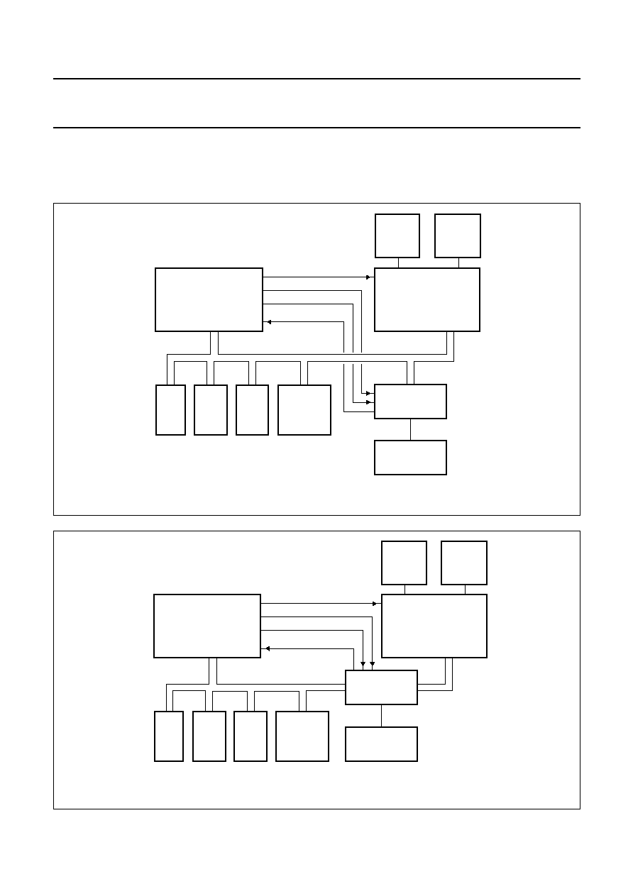
10.1
Application examples of the multi-master mode
The SAA7240 supports a multi-master mode. The SAA7240 is always the bus arbiter of the External Bus Interface Unit
(EBIU) bus. The possible configurations are depicted in Figs 5 and 6.
handbook, full pagewidth
ROM
FLASH
SDRAM
PERIPHERAL
GATEWAY
SAA7215
SAA7240
BPN
BGN
BRN
AV PES
FCE813
EBIU BUS
CO-PROCESSOR
16-Mbit
VIDEO
16-Mbit
GRAPHICS
Fig.5 Multi-master mode; EBIU bus is shared with a co-processor.
handbook, full pagewidth
ROM
FLASH
SDRAM
PERIPHERAL
CO-PROCESSOR
GATEWAY
16-Mbit
VIDEO
16-Mbit
GRAPHICS
SAA7215
SAA7240
BPN
BGN
BRN
AV PES
FCE814
EBIU BUS
SAA7215 BUS
Fig.6 Multi-master mode; EBIU bus is split with a co-processor.

2001 Oct 22
24
Philips Semiconductors
Product specification
MPEG-2 Transport RISC processor
SAA7240
10.2
Memory configurations
Figures 7 and 8 show some examples of typical set-top box memory configurations.
handbook, full pagewidth
FCE816
SAA7240
SAA7215
DRAM/
SDRAM
SDRAM
(MPEG)
PROM
16
8
16
FLASH
RESERVED
16
16
Fig.7 Typical low-end memory configuration; data bus is 16 bits wide.
handbook, full pagewidth
FCE817
SAA7240
SAA7215
DRAM/
SDRAM
SDRAM
(MPEG)
PROM
32
32
16
16
FLASH-1
FLASH-2
16
16
SDRAM
GRAPHICS
Fig.8 Typical high-end configuration; data bus is 32 bits wide.
2001 Oct 22
25
Philips Semiconductors
Product specification
MPEG-2 Transport RISC processor
SAA7240
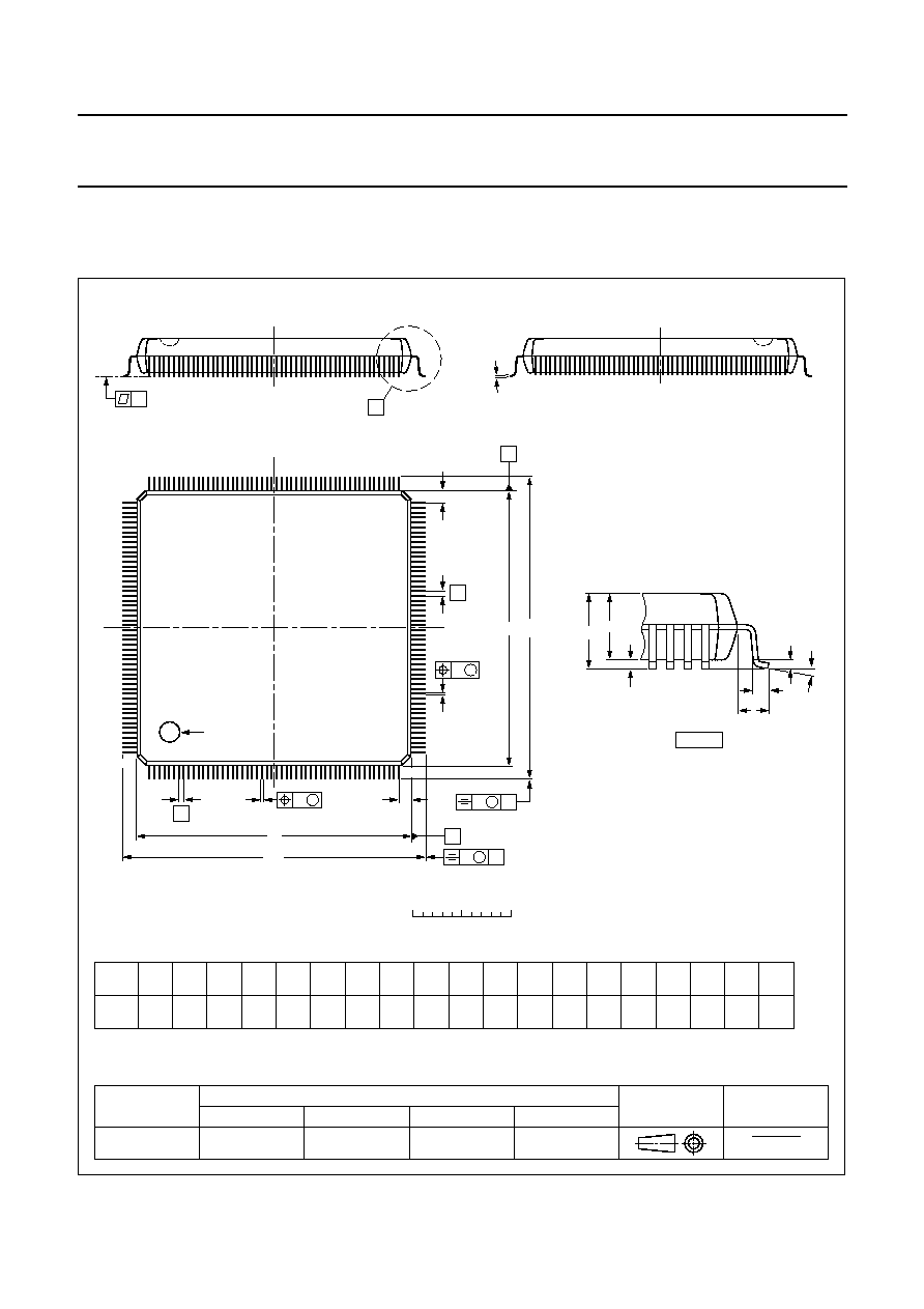
11 PACKAGE OUTLINE
UNIT
A
1
A
2
A
3
b
p
c
E
(1)
e
H
E
L
L
p
Z
y
w
v
REFERENCES
OUTLINE
VERSION
EUROPEAN
PROJECTION
ISSUE DATE
IEC
JEDEC
EIAJ
mm
0.50
0.25
3.6
3.2
0.25
0.27
0.17
0.20
0.09
28.1
27.9
0.5
30.9
30.3
1.39
1.11
8
0
o
o
0.08
0.2
1.3
0.08
DIMENSIONS (mm are the original dimensions)
Note
1. Plastic or metal protrusions of 0.25 mm maximum per side are not included.
0.75
0.45
SOT316-1
MS-029
99-12-27
00-01-25
D
(1)
(1)
(1)
28.1
27.9
H
D
30.9
30.3
E
Z
1.39
1.11
D
pin 1 index
b
p
e
E
A
1
A
L
p
detail X
L
(A )
3
B
52
c
D
H
b
p
E
H
A
2
v
M
B
D
Z D
A
Z E
e
v
M
A
X
1
208
157
156
105
104
53
y
w
M
w
M
0
5
10 mm
scale
208 leads (lead length 1.3 mm); body 28 x 28 x 3.4 mm; high stand-off height
SQFP208: plastic shrink quad flat package;
SOT316-1
A
max.
4.10

2001 Oct 22
26
Philips Semiconductors
Product specification
MPEG-2 Transport RISC processor
SAA7240
12 SOLDERING
12.1
Introduction to soldering surface mount
packages
This text gives a very brief insight to a complex technology.
A more in-depth account of soldering ICs can be found in
our
"Data Handbook IC26; Integrated Circuit Packages"
(document order number 9398 652 90011).
There is no soldering method that is ideal for all surface
mount IC packages. Wave soldering can still be used for
certain surface mount ICs, but it is not suitable for fine pitch
SMDs. In these situations reflow soldering is
recommended.
12.2
Reflow soldering
Reflow soldering requires solder paste (a suspension of
fine solder particles, flux and binding agent) to be applied
to the printed-circuit board by screen printing, stencilling or
pressure-syringe dispensing before package placement.
Several methods exist for reflowing; for example,
convection or convection/infrared heating in a conveyor
type oven. Throughput times (preheating, soldering and
cooling) vary between 100 and 200 seconds depending
on heating method.
Typical reflow peak temperatures range from
215 to 250
∞
C. The top-surface temperature of the
packages should preferable be kept below 220
∞
C for
thick/large packages, and below 235
∞
C for small/thin
packages.
12.3
Wave soldering
Conventional single wave soldering is not recommended
for surface mount devices (SMDs) or printed-circuit boards
with a high component density, as solder bridging and
non-wetting can present major problems.
To overcome these problems the double-wave soldering
method was specifically developed.
If wave soldering is used the following conditions must be
observed for optimal results:
∑
Use a double-wave soldering method comprising a
turbulent wave with high upward pressure followed by a
smooth laminar wave.
∑
For packages with leads on two sides and a pitch (e):
≠ larger than or equal to 1.27 mm, the footprint
longitudinal axis is preferred to be parallel to the
transport direction of the printed-circuit board;
≠ smaller than 1.27 mm, the footprint longitudinal axis
must be parallel to the transport direction of the
printed-circuit board.
The footprint must incorporate solder thieves at the
downstream end.
∑
For packages with leads on four sides, the footprint must
be placed at a 45
∞
angle to the transport direction of the
printed-circuit board. The footprint must incorporate
solder thieves downstream and at the side corners.
During placement and before soldering, the package must
be fixed with a droplet of adhesive. The adhesive can be
applied by screen printing, pin transfer or syringe
dispensing. The package can be soldered after the
adhesive is cured.
Typical dwell time is 4 seconds at 250
∞
C.
A mildly-activated flux will eliminate the need for removal
of corrosive residues in most applications.
12.4
Manual soldering
Fix the component by first soldering two
diagonally-opposite end leads. Use a low voltage (24 V or
less) soldering iron applied to the flat part of the lead.
Contact time must be limited to 10 seconds at up to
300
∞
C.
When using a dedicated tool, all other leads can be
soldered in one operation within 2 to 5 seconds between
270 and 320
∞
C.

2001 Oct 22
27
Philips Semiconductors
Product specification
MPEG-2 Transport RISC processor
SAA7240
12.5
Suitability of surface mount IC packages for wave and reflow soldering methods
Notes
1. All surface mount (SMD) packages are moisture sensitive. Depending upon the moisture content, the maximum
temperature (with respect to time) and body size of the package, there is a risk that internal or external package
cracks may occur due to vaporization of the moisture in them (the so called popcorn effect). For details, refer to the
Drypack information in the
"Data Handbook IC26; Integrated Circuit Packages; Section: Packing Methods".
2. These packages are not suitable for wave soldering as a solder joint between the printed-circuit board and heatsink
(at bottom version) can not be achieved, and as solder may stick to the heatsink (on top version).
3. If wave soldering is considered, then the package must be placed at a 45
∞
angle to the solder wave direction.
The package footprint must incorporate solder thieves downstream and at the side corners.
4. Wave soldering is only suitable for LQFP, TQFP and QFP packages with a pitch (e) equal to or larger than 0.8 mm;
it is definitely not suitable for packages with a pitch (e) equal to or smaller than 0.65 mm.
5. Wave soldering is only suitable for SSOP and TSSOP packages with a pitch (e) equal to or larger than 0.65 mm; it is
definitely not suitable for packages with a pitch (e) equal to or smaller than 0.5 mm.
PACKAGE
SOLDERING METHOD
WAVE
REFLOW
(1)
BGA, HBGA, LFBGA, SQFP, TFBGA
not suitable
suitable
HBCC, HLQFP, HSQFP, HSOP, HTQFP, HTSSOP, HVQFN, SMS
not suitable
(2)
suitable
PLCC
(3)
, SO, SOJ
suitable
suitable
LQFP, QFP, TQFP
not recommended
(3)(4)
suitable
SSOP, TSSOP, VSO
not recommended
(5)
suitable

2001 Oct 22
28
Philips Semiconductors
Product specification
MPEG-2 Transport RISC processor
SAA7240
13 DATA SHEET STATUS
Notes
1. Please consult the most recently issued data sheet before initiating or completing a design.
2. The product status of the device(s) described in this data sheet may have changed since this data sheet was
published. The latest information is available on the Internet at URL http://www.semiconductors.philips.com.
DATA SHEET STATUS
(1)
PRODUCT
STATUS
(2)
DEFINITIONS
Objective data
Development
This data sheet contains data from the objective specification for product
development. Philips Semiconductors reserves the right to change the
specification in any manner without notice.
Preliminary data
Qualification
This data sheet contains data from the preliminary specification.
Supplementary data will be published at a later date. Philips
Semiconductors reserves the right to change the specification without
notice, in order to improve the design and supply the best possible
product.
Product data
Production
This data sheet contains data from the product specification. Philips
Semiconductors reserves the right to make changes at any time in order
to improve the design, manufacturing and supply. Changes will be
communicated according to the Customer Product/Process Change
Notification (CPCN) procedure SNW-SQ-650A.
14 DEFINITIONS
Short-form specification
The data in a short-form
specification is extracted from a full data sheet with the
same type number and title. For detailed information see
the relevant data sheet or data handbook.
Limiting values definition
Limiting values given are in
accordance with the Absolute Maximum Rating System
(IEC 60134). Stress above one or more of the limiting
values may cause permanent damage to the device.
These are stress ratings only and operation of the device
at these or at any other conditions above those given in the
Characteristics sections of the specification is not implied.
Exposure to limiting values for extended periods may
affect device reliability.
Application information
Applications that are
described herein for any of these products are for
illustrative purposes only. Philips Semiconductors make
no representation or warranty that such applications will be
suitable for the specified use without further testing or
modification.
15 DISCLAIMERS
Life support applications
These products are not
designed for use in life support appliances, devices, or
systems where malfunction of these products can
reasonably be expected to result in personal injury. Philips
Semiconductors customers using or selling these products
for use in such applications do so at their own risk and
agree to fully indemnify Philips Semiconductors for any
damages resulting from such application.
Right to make changes
Philips Semiconductors
reserves the right to make changes, without notice, in the
products, including circuits, standard cells, and/or
software, described or contained herein in order to
improve design and/or performance. Philips
Semiconductors assumes no responsibility or liability for
the use of any of these products, conveys no licence or title
under any patent, copyright, or mask work right to these
products, and makes no representations or warranties that
these products are free from patent, copyright, or mask
work right infringement, unless otherwise specified.
ICs with MPEG-2 functionality
Use of this product in
any manner that complies with the MPEG-2 Standard is
expressly prohibited without a license under applicable
patents in the MPEG-2 patent portfolio, which license is
available from MPEG LA, L.L.C., 250 Steele Street, Suite
300, Denver, Colorado 80206.

2001 Oct 22
29
Philips Semiconductors
Product specification
MPEG-2 Transport RISC processor
SAA7240
16 PURCHASE OF PHILIPS I
2
C COMPONENTS
Purchase of Philips I
2
C components conveys a license under the Philips' I
2
C patent to use the
components in the I
2
C system provided the system conforms to the I
2
C specification defined by
Philips. This specification can be ordered using the code 9398 393 40011.

2001 Oct 22
30
Philips Semiconductors
Product specification
MPEG-2 Transport RISC processor
SAA7240
NOTES

2001 Oct 22
31
Philips Semiconductors
Product specification
MPEG-2 Transport RISC processor
SAA7240
NOTES

© Koninklijke Philips Electronics N.V. 2001
SCA73
All rights are reserved. Reproduction in whole or in part is prohibited without the prior written consent of the copyright owner.
The information presented in this document does not form part of any quotation or contract, is believed to be accurate and reliable and may be changed
without notice. No liability will be accepted by the publisher for any consequence of its use. Publication thereof does not convey nor imply any license
under patent- or other industrial or intellectual property rights.
Philips Semiconductors ≠ a worldwide company
Contact information
For additional information please visit http://www.semiconductors.philips.com.
Fax: +31 40 27 24825
For sales offices addresses send e-mail to: sales.addresses@www.semiconductors.philips.com.
Printed in The Netherlands
753504/01/pp
32
Date of release:
2001 Oct 22
Document order number:
9397 750 07749