Document Outline
- 1 FEATURES
- 2 APPLICATIONS
- 3 GENERAL DESCRIPTION
- 4 ORDERING INFORMATION
- 5 BLOCK DIAGRAM
- 6 PINNING
- 7 FUNCTIONAL DESCRIPTION
- 8 LIMITING VALUES
- 9 ELECTRICAL SPECIFICATIONS
- 10 MECHANICAL SPECIFICATIONS
- 11 APPLICATION INFORMATION
- 12 REFERENCE DOCUMENTS
- 13 DATA SHEET STATUS
- 14 DEFINITIONS
- 15 DISCLAIMERS
DATA SHEET
Product specification
Supersedes data of 1999 Oct 01
2002 May 24
INTEGRATED CIRCUITS
SLRM900
I-CODE Long range reader
module hardware

2002 May 24
2
Philips Semiconductors
Product specification
I-CODE Long range reader
module hardware
SLRM900
CONTENTS
1
FEATURES
2
APPLICATIONS
3
GENERAL DESCRIPTION
4
ORDERING INFORMATION
5
BLOCK DIAGRAM
6
PINNING
6.1
Antenna connector
6.2
Serial interface connector
6.3
Power supply connector
6.4
Switches
6.5
PCB connector
7
FUNCTIONAL DESCRIPTION
7.1
System overview
7.1.1
I-CODE labels
7.1.2
Host
7.1.3
I/O ports
7.1.4
Antenna
7.1.5
Power supply
7.2
Reader software
7.3
Reader hardware
7.3.1
RF board
7.3.1.1
Voltage regulation
7.3.1.2
Clock generator
7.3.1.3
Modulator and transmitter amplifier
7.3.1.4
Modulation index and RF power regulation
7.3.1.5
Receiver, filter, demodulator, and ADC
7.3.1.6
Opto-couplers
7.3.2
Microcontroller board
7.3.2.1
Microcontroller
7.3.2.2
RS232 interface
7.4
Printed circuit boards
7.5
EMC and EMI
7.6
Safety and reliability considerations
7.6.1
Antenna rupture and antenna short-circuit
7.6.2
Supply voltage
8
LIMITING VALUES
9
ELECTRICAL SPECIFICATIONS
10
MECHANICAL SPECIFICATIONS
11
APPLICATION INFORMATION
11.1
Jumper settings
11.2
Hints for system integration
12
REFERENCE DOCUMENTS
13
DATA SHEET STATUS
14
DEFINITIONS
15
DISCLAIMERS
2002 May 24
3
Philips Semiconductors
Product specification
I-CODE Long range reader
module hardware
SLRM900
1
FEATURES
∑
24 V DC power supply
∑
13.56 MHz carrier frequency
∑
RS232 serial interface, 115.2 or 57.6 kbaud data rate
∑
Regulated RF output power, software adjustable from
2 up to 10 W at 50
∑
Software adjustable modulation index from 10% to 20%
∑
Firmware upgradable via RS232 interface
∑
Programmable input and output ports (optional)
∑
Electronic Article Surveillance (EAS) stand-alone mode
(EAS output signal optional)
∑
Anticollision capability
∑
Support of both standard and fast mode
∑
BundesAmt fuer Post und Telekommunikation (BAPT)
and Federal Communications Commission (FCC)
approval
∑
CE compliant.
2
APPLICATIONS
∑
Long range reading appliances in I-CODE
(1)
systems.
3
GENERAL DESCRIPTION
Generally, the SLRM900 can communicate with smart
labels based on Philips I-CODE1 label IC SL1ICS3001.
It consists of a 2-way communication transmitter and
receiver, for generating, transmitting, receiving, and
processing identification signals.
Optional input and output ports, and an RS232 interface
offer the possibility to connect the unit to a microcontroller
or PC.
The SLRM900 is designed to access all types of labels and
transponders that are based on the I-CODE1 label IC.
Read and write functionality is included, as well as
sophisticated ways to use the anticollision capability of
I-CODE.
High emphasis is put on long range functionality, which
makes the SLRM900 suitable for gate antennas and
tunnel reader applications. In order to provide the
appropriate output power level for various types of
connected antennas, the output power may be adjusted,
using simple software configuration commands.
Many reference installations with high demands on
anticollision, reading range, and data reliability in noisy
environments, have proven the capability of both the
reader module and the I-CODE1 label IC.
This document describes the reader hardware, interface,
and connection of the antenna.
(1) I-CODE - is a trademark of Koninklijke Philips Electronics N.V.
4
ORDERING INFORMATION
PART NUMBER
NAME
ORDERING CODE (12NC)
SLRM900/AFB
I-CODE Long range reader module
9352 623 27122
2002 May 24
4
Philips Semiconductors
Product specification
I-CODE Long range reader
module hardware
SLRM900
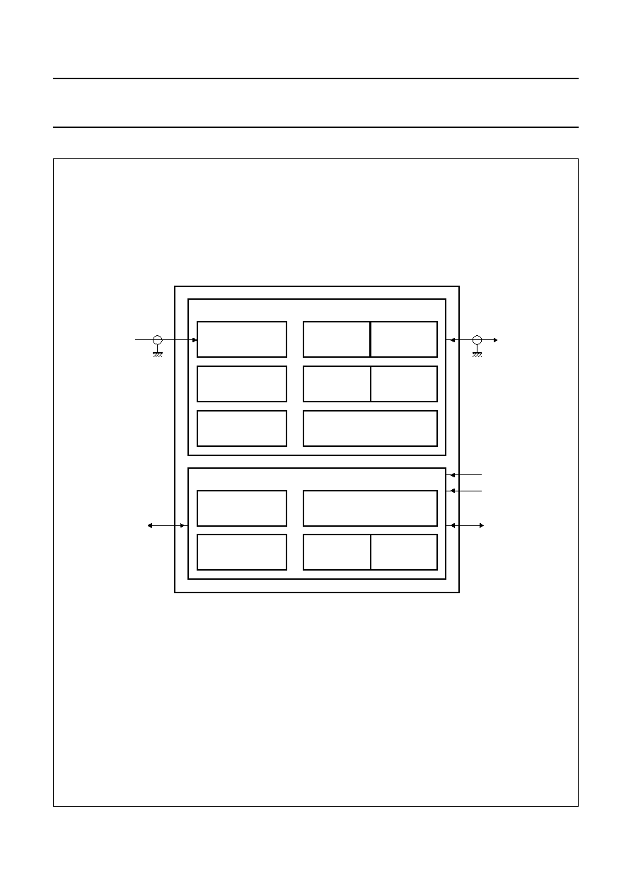
5
BLOCK DIAGRAM
handbook, full pagewidth
MGW307
VOLTAGE
REGULATION
MODULATOR
MODULATION
INDEX
ADJUSTMENT
RF POWER
REGULATION
TRANSMITTER
AMPLIFIER
13.56 MHz
CLOCK GENERATOR
(AND DIVIDER)
OPTO COUPLERS
ADC
RS232 DRIVER
MICROCONTROLLER
UNIT
MICROCONTROLLER BOARD
RF BOARD
FLASH
EPROM
RAM
RECEIVER, FILTER
AND DEMODULATOR
I/O
(optional)
SW1
SW2
antenna
serial
interface
power
supply
+
24 V DC
Fig.1 Block diagram.

2002 May 24
5
Philips Semiconductors
Product specification
I-CODE Long range reader
module hardware
SLRM900
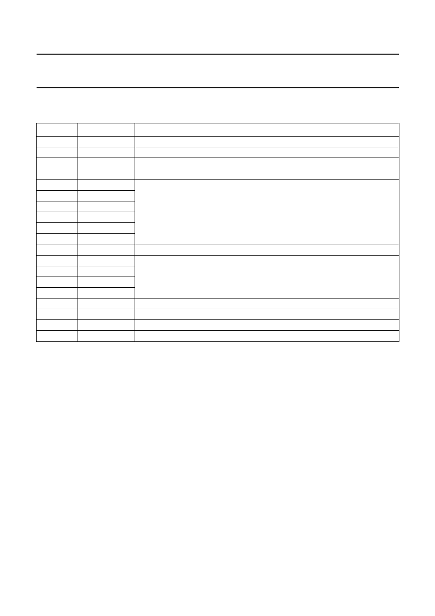
6
PINNING
The locations of the connectors and switches are shown
in Fig.9.
6.1
Antenna connector
ST3 in Fig.8.
6.2
Serial interface connector
ST2 in Fig.8; see Fig.3 for front view of connector.
6.3
Power supply connector
See Fig.4 for front view of connector
6.4
Switches
See Fig.5 for front view of switches.
SYMBOL
DESCRIPTION
ANT
antenna input and output; BNC female
GND
antenna ground
SYMBOL
PIN
DESCRIPTION
I/O
1
internally connected for DCE
TxD
2
output
RxD
3
input
I/O
4
internally connected for DCE
GND
5
ground
I/O
6
internally connected for DCE
I/O
7
internally connected for DCE
I/O
8
internally connected for DCE
RFU
9
ready for use
MGW308
handbook, halfpage
GND
ANT
Fig.2 Antenna connector.
MGW310
handbook, halfpage
1
5
6
9
Fig.3 RS232 connector D-sub.
SYMBOL
DESCRIPTION
+24VDC
power supply voltage; DC-jack (
2.1 mm)
GND
power supply ground
SYMBOL
DESCRIPTION
RST
Resets the SLRM900. By resetting the
SLRM900, all programmable parameters
will be preset to their default values
described in data sheet:
"SLRM900 I-CODE
Long Range Reader Module, protocol
Reader-Host", except for stored RF output
power and modulation index. The SLRM900
will restart with the mode selected by jumper
JP3 (see Table 3).
NMI
Non Maskable Interrupt. To change from the
default start-up mode to the alternative
mode (see setting of jumper JP3 in Table 3).
For switching back to default start-up mode,
press switch RST (SW1).
MGW309
handbook, halfpage
GND
+
24VDC
Fig.4 Power supply connector.
MGW311
handbook, halfpage
SW1 (RST)
SW2 (NMI)
Fig.5 Switches SW1 and SW2.
2002 May 24
6
Philips Semiconductors
Product specification
I-CODE Long range reader
module hardware
SLRM900
6.5
PCB connector
ST3 in Fig.8.
Notes
1. For the electrical characteristics of all input and output ports, please refer to the specification
"SAB-C167CR-LM".
2. For programming of the input and output ports, please refer to data sheet
"SLRM900 I-CODE Long Range Reader
Module protocol, Reader-Host".
SYMBOL
PIN
DESCRIPTION
RFU
A1 to A31
ready for use
GND
A32
ground
RFU
B1 to B32
ready for use
RFU
C1 to C3
ready for use
IN5
C4
programmable input ports IN5 to IN0; notes 1 and 2
IN4
C5
IN3
C6
IN2
C7
IN1
C8
IN0
C9
RFU
C10 to C13
ready for use
OUT3
C14
programmable output ports OUT3 to OUT0; notes 1 and 2
OUT2
C15
OUT1
C16
OUT0
C17
RFU
C18 to C24
ready for use
EAS OUT
C25
programmable EAS alarm output
RFU
C26 to C31
ready for use
OUT
C32
ground
2002 May 24
7
Philips Semiconductors
Product specification
I-CODE Long range reader
module hardware
SLRM900
7
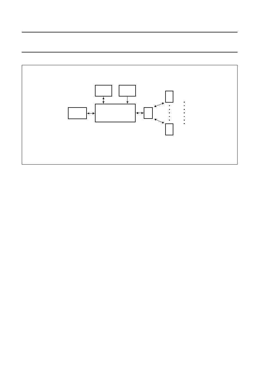
FUNCTIONAL DESCRIPTION
handbook, full pagewidth
MGW306
I/O
(optional)
HOST
SYSTEM
SLRM900
antenna
I - CODE label 1
I - CODE label n
POWER
SUPPLY
Fig.6 System overview.
7.1
System overview
The SLRM900 is part of a complete Radio Frequency
Identification (RFID) system (see Fig.6).
The SLRM900 can communicate with I-CODE smart
labels. The device consists of a two-way communication
transmitter and receiver, for generating, transmitting,
receiving, and processing identification signals.
In the transmit mode, the microcontroller board generates
data whereas the RF board uses this signal to modulate a
carrier. This modulated carrier will be amplified, and
transmitted by the antenna to the label. This label will
subsequently generate its response, which will be
picked-up by the SLRM900 in the receive mode, and
processed by the digital hardware.
By using the RS232 serial interface (or the optional input
and output ports) the output parameters of the module can
be set.
7.1.1
I-CODE labels
The SLRM900 is designed for communication with smart
labels based on Philips I-CODE1 label IC SL1ICS3001.
7.1.2
H
OST
The connection to the host (e.g. microcontroller or PC) is a
serial interface on RS232 level for data transmission. For
the protocol please refer to data sheet
"SLRM900 I-CODE
Long Range Reader Module, protocol Reader-Host".
7.1.3
I/O
PORTS
There are 6 input ports, 4 output ports, and one EAS
signal output port available on the microcontroller board
(see Section 6.5). These ports are software
programmable. The input and output ports are not lead out
of the metal housing and therefore not ESD protected.
7.1.4
A
NTENNA
A 50
antenna has to be connected to the antenna
connector. This antenna has to be designed according to
application note
"I-CODE design of Read/Write antennas".
7.1.5
P
OWER SUPPLY
To work with the SLRM900, an external linear regulated
power supply has to be used. Using the supplied power
supply cable is recommended, in order to comply with the
EMC and EMI limits (see Section 7.5).
The reader module contains filtering circuitries for the
power supply. However, some requirements are to be
fulfilled by the power supply. The maximum ripple of the
supply voltage must not exceed the maximum values
specified in Table 2.
2002 May 24
8
Philips Semiconductors
Product specification
I-CODE Long range reader
module hardware
SLRM900
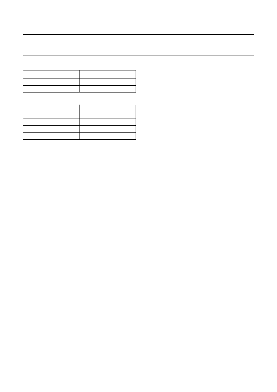
Table 1
DC power supply output voltage
Table 2
DC power supply ripple voltage
7.2
Reader software
The available software for the SLRM900 is contained in
document
"SLRM900 I-CODE Long Range Reader
Module, protocol Reader-Host".
7.3
Reader hardware
The internal electronics of the SLRM900 can be divided in
two major units:
∑
RF board (see Fig.7)
∑
Microcontroller board (see Fig.8).
7.3.1
RF
BOARD
7.3.1.1
Voltage regulation
All necessary internal voltages for the module are derived
internally from the 24 V DC power supply voltage.
7.3.1.2
Clock generator
This part generates the 13.56 MHz clock frequency for the
transmitter amplifier. A divided clock signal is connected to
the microcontroller for synchronization purposes.
7.3.1.3
Modulator and transmitter amplifier
To transmit data to the I-CODE labels, the carrier has to be
modulated by the modulator with a digital signal from the
microcontroller according to data sheet
"SL1ICS3001
I-CODE Label IC, protocol air interface". The transmitter
amplifier amplifies the modulated carrier signal.
7.3.1.4
Modulation index and RF power regulation
The RF power regulator keeps the antenna output voltage
to a level determined by software settings. Also, by using
software settings, the modulation index can be set,
according to data sheet
"SL1ICS3001 I-CODE Label IC".
The required modulation index has to be re-adjusted after
any change of the RF output power and at large
temperature variations.
7.3.1.5
Receiver, filter, demodulator, and ADC
An amplitude modulated signal is received from the
I-CODE1 label IC. After filtering, demodulation, and
amplification, the analog data signal is converted by the
12-bit ADC for further digital processing.
7.3.1.6
Opto-couplers
All internal analog and digital signals between the
RF board and microcontroller board are galvanically
separated by opto-couplers.
7.3.2
M
ICROCONTROLLER BOARD
7.3.2.1
Microcontroller
The microcontroller processes the protocol for the
communication between the I-CODE labels and the
SLRM900. The serial interface signals are converted in
such a way, that the labels are able to process them, and
the outgoing signals from the labels are converted into
serial interface-compatible signals.
Another important microcontroller task is its control
function. Software control offers the possibility to change
both the RF-output power and the modulation index.
7.3.2.2
RS232 interface
The device communicates with the host (processor or PC)
via a serial interface, using a jumper-selectable baud rate
of either 57.6 kbaud in standard mode, or 115.2 kbaud in
fast mode (see setting for JP4 in Table 3).
OUTPUT PARAMETER
VALUE
DC supply voltage
+24 V
DC current
2 A
RIPPLE FREQUENCY
MAXIMUM
RIPPLE VOLTAGE
50 Hz
f < 10 MHz
100 mV (p-p)
10 MHz
f < 20 MHz
50 mV (p-p)
f
20 MHz
100 mV (p-p)
2002 May 24
9
Philips Semiconductors
Product specification
I-CODE Long range reader
module hardware
SLRM900
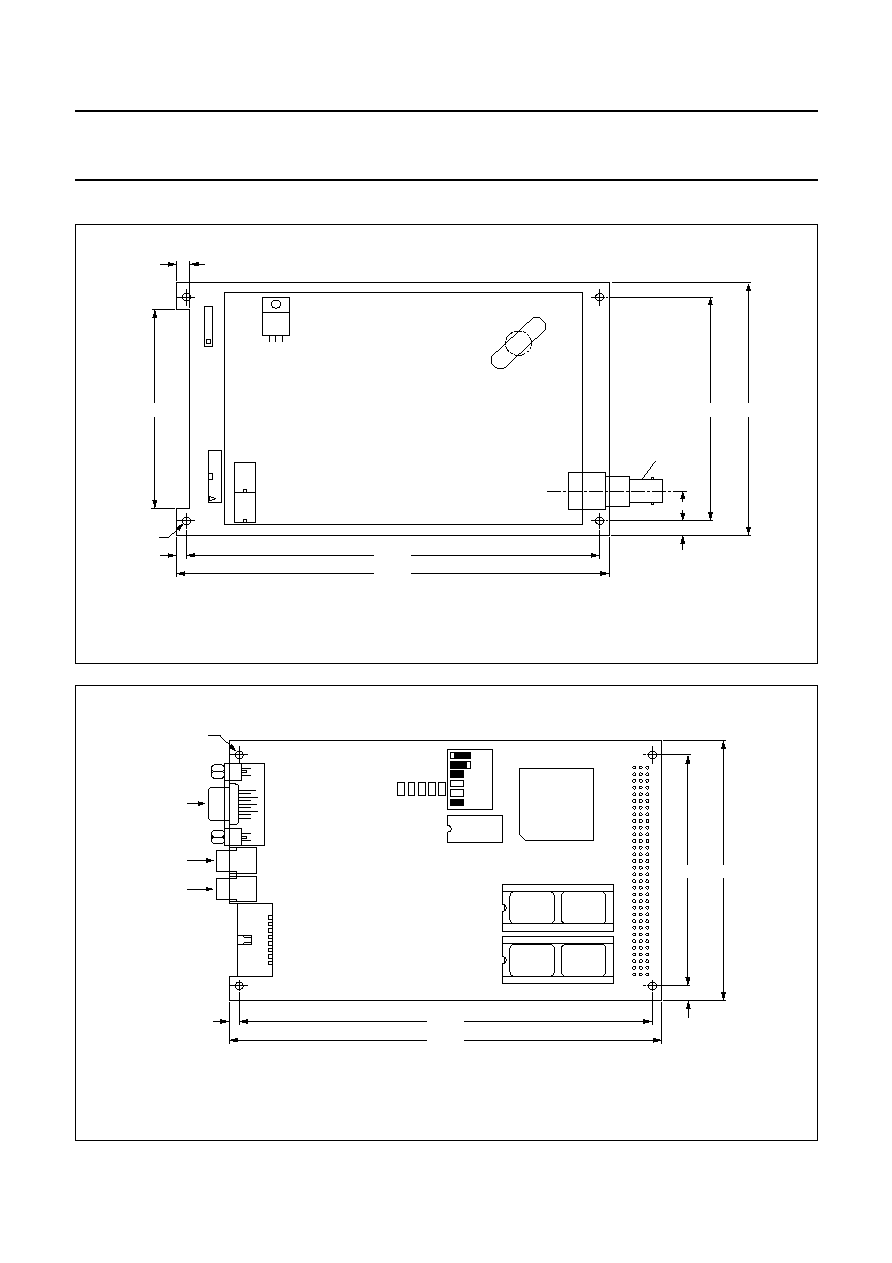
7.4
Printed circuit boards
handbook, full pagewidth
MGW313
152.84
3.58
3.00
160.00
all dimensions are in mm
4.90
11.40
antenna
connector
5.56
78.60
88.88
100.00
Fig.7 Analog RF board I-CODEHFE3.
handbook, full pagewidth
MGW314
152.84
3.58
3.00
ST2
SW1
SW2
160.00
JP5
JP6
JP2
JP1
JP3
JP4
5.56
88.88
ST3
1
32
C
B
A
100.00
all dimensions are in mm
Fig.8 Digital microcontroller board I-CODE
µ
PE1.

2002 May 24
10
Philips Semiconductors
Product specification
I-CODE Long range reader
module hardware
SLRM900
7.5
EMC and EMI
The SLRM900 is designed in such a way that it is possible
to build systems with it, which are in conformance with
EMC and EMI standards.
Electromagnetic emissions comply with the guidelines in
BAPT 222 ZV 122 and EN 300 330. Electromagnetic
immunity complies with the guidelines in ETS 300 683.
The conformance to EMC and EMI standards can only be
granted for systems, not for components.
The following measurements have been passed:
∑
EMI: EN 300 330, BAPT 222 ZV 122, FCC 47 part 15
∑
Immunity: ETS 300 683.
The following configuration is in compliance with the
telecommunication standards:
∑
SLRM900: output power 4 W at 50
; modulation index
m = 15%; standard mode
∑
Linear power supply (according to the recommendations
in Table 1), connected via the supplied power supply
cable
∑
Antenna from the I-CODE evaluation kit:
≠ size: 38 cm
◊
28 cm
≠ number of turns: N = 1
≠ quality factor: Q = 30
≠ impedance:
Z
= 50
≠
= 0
∞
≠ according to application note
"I-CODE, Design of
Read/Write antennas".
7.6
Safety and reliability considerations
The SLRM900 has implemented measures for high
reliability.
7.6.1
A
NTENNA RUPTURE AND ANTENNA SHORT
-
CIRCUIT
The SLRM900 does not immediately get damaged in case
of either an antenna short-circuit, or an antenna rupture
with short duration. However, permanent antenna
short-circuit, or antenna rupture, will definitely damage the
SLRM900. The supply current of the SLRM900 will be
limited at typical 1.6 A.
7.6.2
S
UPPLY VOLTAGE
The SLRM900 is protected against short supply voltage
peaks and incorrect polarity for a short time, but
permanent incorrect supply will definitely damage the
device.
2002 May 24
11
Philips Semiconductors
Product specification
I-CODE Long range reader
module hardware
SLRM900
8
LIMITING VALUES
In accordance with the Absolute Maximum Rating System (IEC 60134).
9
ELECTRICAL SPECIFICATIONS
T
amb
= 0 to 70
∞
C; antenna load is 50
; unless otherwise specified.
Notes
1. Typical ratings are not guaranteed. These values listed are at T
amb
= 25
∞
C.
2. Values listed above are continuous currents; peak values can be up to 650 mA higher, by switching, or modulating
the RF carrier.
3. Calculated from the measured RF output voltage across a 50
load; RF output voltage measured with Tektronix
TDS520B oscilloscope.
4. Default value, adjusted at delivery.
5. Definition:
where V
max
is RF level without modulation and V
min
is RF level during modulation.
Modulation method is Amplitude Shift Keying (ASK).
SYMBOL
PARAMETER
MIN.
MAX.
UNIT
V
dd
supply voltage
-
0.6
+27
V
T
amb
ambient temperature
0
70
∞
C
T
case
operating in-case temperature
0
85
∞
C
T
stg
storage temperature
-
25
+85
∞
C
SYMBOL
PARAMETER
CONDITIONS
MIN.
TYP.
(1)
MAX.
UNIT
V
dd
DC supply voltage
23
24
25
V
I
dd
DC supply current
P
o
= 4 W; note 2
-
0.975
1.100
A
P
o
= 8 W; note 2
-
1.215
1.350
A
P
out
RF output power
calculated: note 3
minimum
-
2
4
(4)
W
maximum
8
10
-
W
m
adjustable modulation index
note 5
10
15
(4)
20
%
m
V
max
V
min
≠
V
max
V
min
+
------------------------------
=
2002 May 24
12
Philips Semiconductors
Product specification
I-CODE Long range reader
module hardware
SLRM900
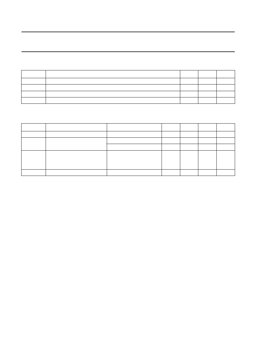
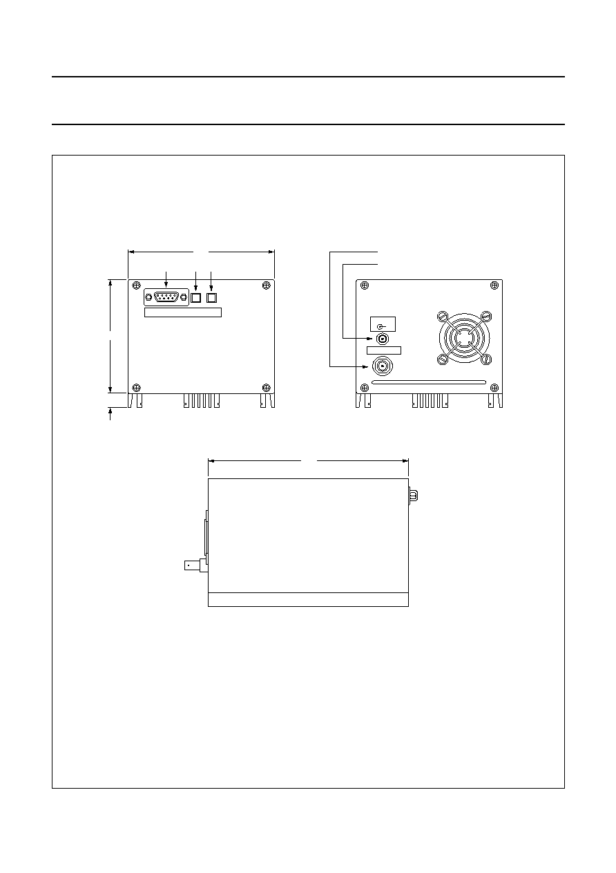
10 MECHANICAL SPECIFICATIONS
handbook, full pagewidth
MGW312
INTERFACE
RST NMI
ANTENNA
power supply connector
REAR VIEW
SIDE VIEW
FRONT VIEW
antenna connector
antenna
connector
24V DC
+
164
105
ST2
SW1 SW2
84
11
all dimensions are in mm
Fig.9 Views and dimensions.
2002 May 24
13
Philips Semiconductors
Product specification
I-CODE Long range reader
module hardware
SLRM900
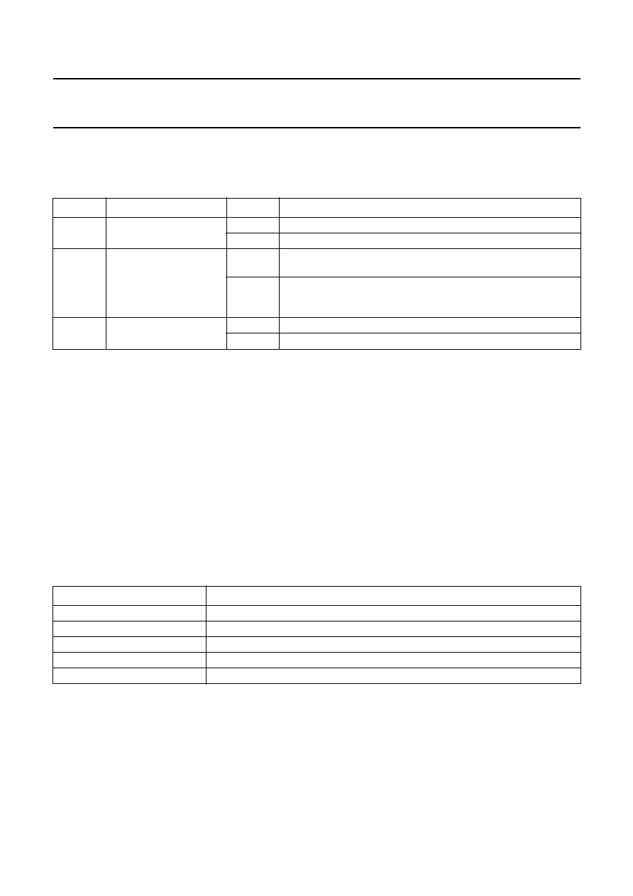
11 APPLICATION INFORMATION
11.1
Jumper settings
Table 3
Jumper settings on microcontroller board I-CODE
µ
PE1 (see Fig.8)
The settings of JP1, JP5 and JP6 must not be changed.
NAME
FUNCTION
SETTING
DESCRIPTION
JP2
bootstrap loader mode
not set
bootstrap loader mode disabled (default)
set
for firmware update via RS232
JP3
start-up mode
not set
PC mode (default); the reader starts up expecting commands from
the host
set
stand-alone EAS mode; the reader is transmitting EAS commands
continuously after start-up; if a label with EAS bits set is detected,
the EAS Out port will change to HIGH level
JP4
baud rate
not set
serial communication interface baud rate at 57.6 kbaud (default)
set
serial communication interface baud rate at 115.2 kbaud
11.2
Hints for system integration
The following list should be checked if any problem (e.g.
reduced read and write distances) occurs:
∑
Power supply cable is not correctly plugged into the
power supply
∑
Power supply is out of specification (see Table1)
∑
Serial interface not properly connected
∑
Serial interface cable, power supply cable or antenna
cable are too close to the antenna
∑
Interference received by the antenna because of an
external noise source; the remedy is the removal of the
antenna from the interfering area and execute the
command CRM_config(CFG_INIT,0). See data sheet
"SLRM900; I-CODE Long Range Reader Module,
protocol Reader-Host"
∑
Antenna is mounted in metal environment; the remedy is
to place a non-metal space keeper between the antenna
and the metal
∑
Antenna is not designed according to application note
"I-CODE, Design of Read/Write antennas".
12 REFERENCE DOCUMENTS
Table 4
Survey of reference documents
CATEGORY
NUMBER OR TITLE
Application note
"I-CODE, Design of Read/Write antennas"
Specification
"SAB-C167CR-LM"
Data sheet
"SLRM900; I-CODE Long Range Reader Module, protocol Reader-Host"
Data sheet
"SL1ICS3001; I-CODE1 Label IC"
Data sheet
"SL1ICS3001; I-CODE1 Label IC, protocol air interface"

2002 May 24
14
Philips Semiconductors
Product specification
I-CODE Long range reader
module hardware
SLRM900
13 DATA SHEET STATUS
Notes
1. Please consult the most recently issued data sheet before initiating or completing a design.
2. The product status of the device(s) described in this data sheet may have changed since this data sheet was
published. The latest information is available on the Internet at URL http://www.semiconductors.philips.com.
DATA SHEET STATUS
(1)
PRODUCT
STATUS
(2)
DEFINITIONS
Objective data
Development
This data sheet contains data from the objective specification for product
development. Philips Semiconductors reserves the right to change the
specification in any manner without notice.
Preliminary data
Qualification
This data sheet contains data from the preliminary specification.
Supplementary data will be published at a later date. Philips
Semiconductors reserves the right to change the specification without
notice, in order to improve the design and supply the best possible
product.
Product data
Production
This data sheet contains data from the product specification. Philips
Semiconductors reserves the right to make changes at any time in order
to improve the design, manufacturing and supply. Changes will be
communicated according to the Customer Product/Process Change
Notification (CPCN) procedure SNW-SQ-650A.
14 DEFINITIONS
Short-form specification
The data in a short-form
specification is extracted from a full data sheet with the
same type number and title. For detailed information see
the relevant data sheet or data handbook.
Limiting values definition
Limiting values given are in
accordance with the Absolute Maximum Rating System
(IEC 60134). Stress above one or more of the limiting
values may cause permanent damage to the device.
These are stress ratings only and operation of the device
at these or at any other conditions above those given in the
Characteristics sections of the specification is not implied.
Exposure to limiting values for extended periods may
affect device reliability.
Application information
Applications that are
described herein for any of these products are for
illustrative purposes only. Philips Semiconductors make
no representation or warranty that such applications will be
suitable for the specified use without further testing or
modification.
15 DISCLAIMERS
Life support applications
These products are not
designed for use in life support appliances, devices, or
systems where malfunction of these products can
reasonably be expected to result in personal injury. Philips
Semiconductors customers using or selling these products
for use in such applications do so at their own risk and
agree to fully indemnify Philips Semiconductors for any
damages resulting from such application.
Right to make changes
Philips Semiconductors
reserves the right to make changes, without notice, in the
products, including circuits, standard cells, and/or
software, described or contained herein in order to
improve design and/or performance. Philips
Semiconductors assumes no responsibility or liability for
the use of any of these products, conveys no licence or title
under any patent, copyright, or mask work right to these
products, and makes no representations or warranties that
these products are free from patent, copyright, or mask
work right infringement, unless otherwise specified.

2002 May 24
15
Philips Semiconductors
Product specification
I-CODE Long range reader
module hardware
SLRM900
NOTES

© Koninklijke Philips Electronics N.V. 2002
SCA74
All rights are reserved. Reproduction in whole or in part is prohibited without the prior written consent of the copyright owner.
The information presented in this document does not form part of any quotation or contract, is believed to be accurate and reliable and may be changed
without notice. No liability will be accepted by the publisher for any consequence of its use. Publication thereof does not convey nor imply any license
under patent- or other industrial or intellectual property rights.
Philips Semiconductors ≠ a worldwide company
Contact information
For additional information please visit http://www.semiconductors.philips.com.
Fax: +31 40 27 24825
For sales offices addresses send e-mail to: sales.addresses@www.semiconductors.philips.com.
Printed in The Netherlands
613502/02/pp
16
Date of release:
2002 May 24
Document order number:
9397 750 08394