1999 Jan 27
2
Philips Semiconductors
Preliminary specification
Fast charge ICs for NiCd, NiMH, SLA and
LiIon
TEA1102; TEA1102T;
TEA1102TS
FEATURES
∑
Safe and fast charging of Nickel Cadmium (NiCd),
Nickel Metal Hydride (NiMH), Lithium Ion (LiIon), and
Sealed Lead Acid (SLA) batteries
∑
Three charge states for NiCd or NiMH; fast, top-off and
trickle or voltage regulation (optional)
∑
Two charge states for LiIon or SLA; current and voltage
limited
∑
Adjustable fast charge current [0.5CA to 5CA nominal
(CA = Capacity Amperes)]
∑
DC top-off and pulsating trickle charge current (NiCd
and NiMH)
∑
Temperature dependent
T/
t battery full detection
∑
Automatic switch-over to accurate peak voltage
detection (
-
1
/
4
%) if no NTC is applied
∑
Possibility to use both
T/
t and peak voltage detection
as main fast charge termination
∑
Support of inhibit during all charging states
∑
Manual refresh with regulated adjustable discharge
current (NiCd and NiMH)
∑
Voltage regulation in the event of no battery
∑
Support of battery voltage based charge indication and
buzzer signalling at battery insertion, end of refresh and
at full detection
∑
Single, dual and separate LED outputs for indication of
charge status state
∑
Minimum and maximum temperature protection
∑
Time-out protection
∑
Short-circuit battery voltage protection
∑
Can be applied with few low-cost external components.
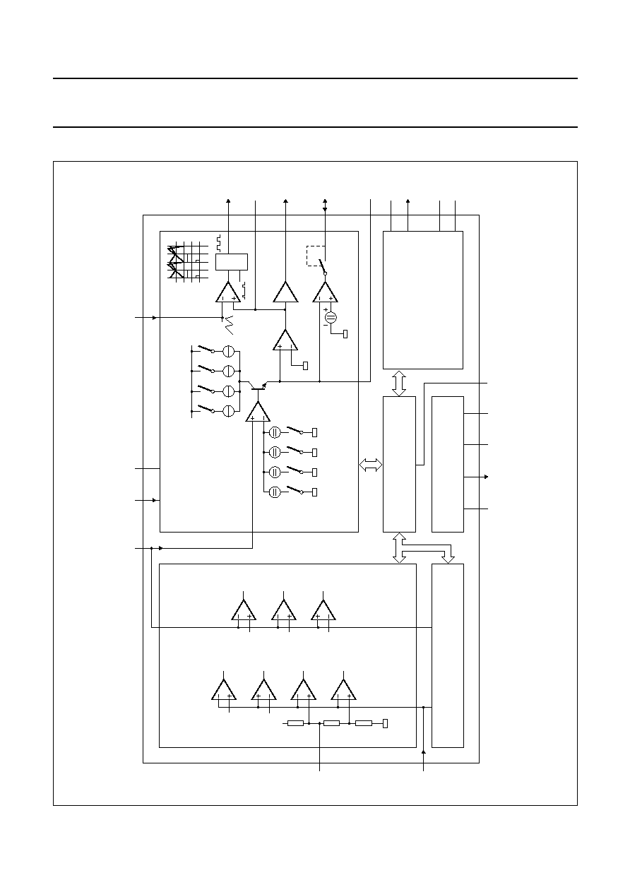
GENERAL DESCRIPTION
The TEA1102x are fast charge ICs which are able fast
charge NiCd and NiMH, SLA and Lilon batteries.
The main fast charge termination for NiCd and NiMH
batteries are
T/
t and peak voltage detection, both of
which are well proven techniques. The TEA1102x
automatically switches over from
T/
t to peak voltage
detection if the thermistor fails or is not present. The
T/
t
detection sensitivity is temperature dependent, thus
avoiding false charge termination. Three charge states
can be distinguished; fast, top-off and trickle.
Charging Lilon and SLA batteries is completely different.
When the batteries reach their maximum voltage
(adjustable), the TEA1102x switches over from current
regulation to voltage regulation. After a defined time
period, which is dependent on battery capacity and charge
current, charge is terminated. Due to small self discharge
rates of Lilon and SLA batteries, trickle charge can be
omitted.
Several LEDs, as well as a buzzer, can be connected to
the TEA1102x for indicating battery insertion, charge
states, battery full condition and protection mode.
The TEA1102x are contained in a 20-pin package and are
manufactured in a BiCMOS process, essentially for
integrating the complex mix of requirements in a single
chip solution. Only a few external low cost components are
required in order to build a state of the art charger.
ORDERING INFORMATION
TYPE
NUMBER
PACKAGE
NAME
DESCRIPTION
VERSION
TEA1102
DIP20
plastic dual in-line package; 20 leads (300 mil)
SOT 146-1
TEA1102T
SO20
plastic small outline package; 20 leads; body width 7.5 mm
SOT163-1
TEA1102TS
SSOP20
plastic shrink small outline package; 20 leads; body width 5.3 mm
SOT339-1

1999 Jan 27
3
Philips Semiconductors
Preliminary specification
Fast charge ICs for NiCd, NiMH, SLA and
LiIon
TEA1102; TEA1102T;
TEA1102TS
QUICK REFERENCE DATA
SYMBOL
PARAMETER
CONDITIONS
MIN.
TYP.
MAX.
UNIT
V
P
supply voltage
5.5
-
11.5
V
I
P
supply current
outputs off
-
4
-
mA
V
NTC
/V
NTC
temperature rate dependent
(
T/
t) detection level
V
NTC
= 2 V;
T
j
= 0 to 50
∞
C
-
-
0.25
-
%
V
bat
/V
bat
voltage peak detection level with
respect to top value
V
bat
= 2 V;
T
j
= 0 to 50
∞
C
-
-
0.25
-
%
I
Vbat
input current battery monitor
V
bat
= 0.3 to 1.9 V
-
1
-
nA
V
bat(l)
voltage at pin 19 for detecting low
battery voltage
-
0.30
-
V
I
IB
battery charge current
fast charge
10
-
100
µ
A
top-off mode
-
3
-
µ
A
I
IB(max)
maximum battery charge current
voltage regulation full
NiCd and NiMH battery
-
10
-
µ
A
I
IB(Lmax)
maximum load current
no battery
-
40
-
µ
A
f
osc
oscillator frequency
10
-
200
kHz
V
reg
regulating voltage
LiIon
-
1.37
-
V
SLA
-
1.63
-
V
NiCd and NiMH
(pin V
stb
open-circuit)
-
1.325 or
V
stb
-
V
open battery
-
1.9
-
V
1999 Jan 27
5
Philips Semiconductors
Preliminary specification
Fast charge ICs for NiCd, NiMH, SLA and
LiIon
TEA1102; TEA1102T;
TEA1102TS
PINNING
SYMBOL
PIN
DESCRIPTION
V
stb
1
standby regulation voltage input
(NiCd and NiMH)
IB
2
charge current setting
GND
3
ground
PSD
4
program pin sample divider
LED
5
LED output
POD
6
program pin oscillator divider
PTD
7
program pin time-out divider
NTC
8
temperature sensing input
MTV
9
maximum temperature voltage
RFSH
10
refresh input/output
FCT
11
fast charge termination and
battery chemistry identification
V
P
12
positive supply voltage
V
sl
13
switched reference voltage output
OSC
14
oscillator input
PWM
15
pulse width modulator output
V
S
16
stabilized reference voltage
LS
17
loop stability pin
AO
18
analog output
V
bat
19
single-cell battery voltage input
R
ref
20
reference resistor pin
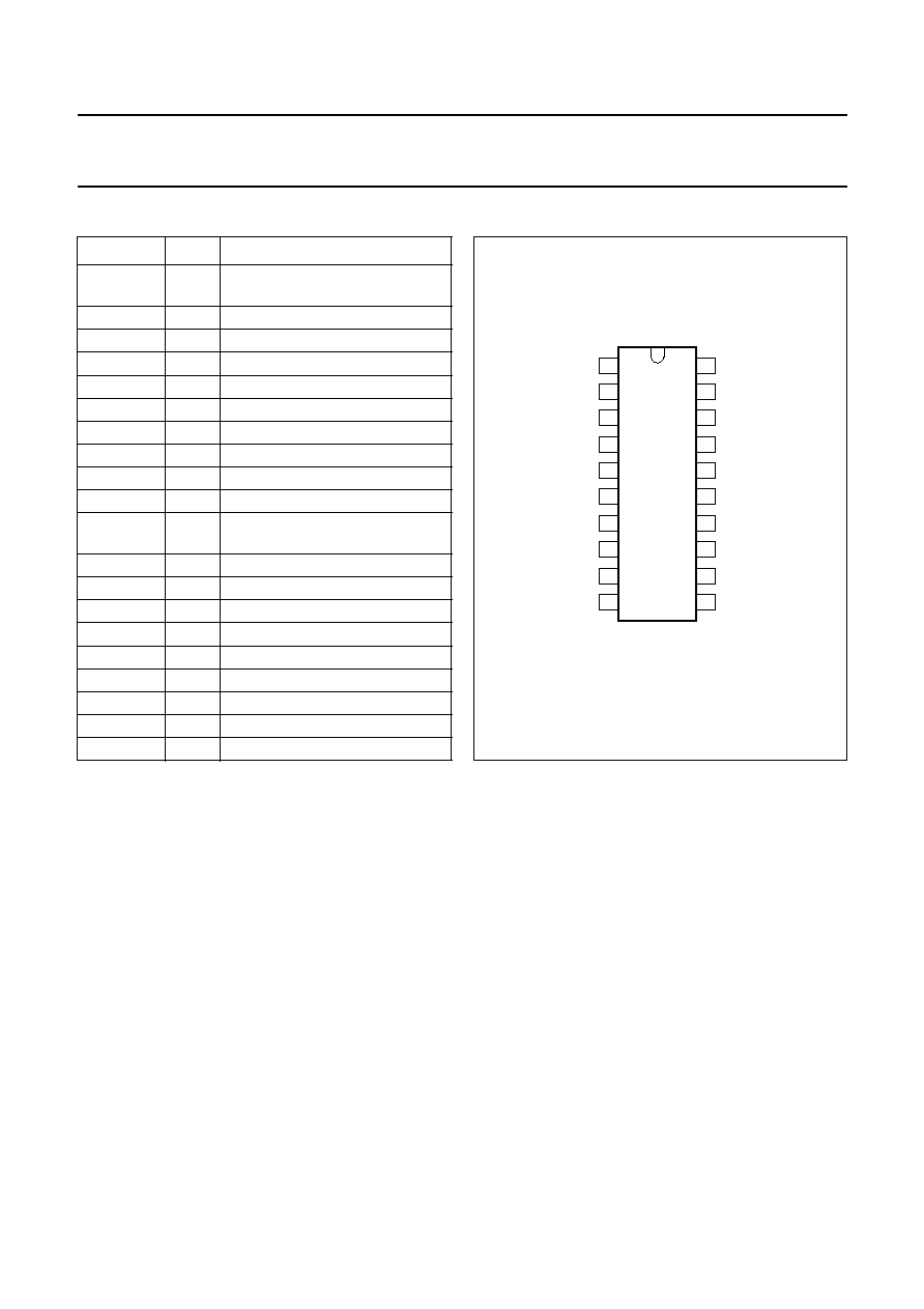
Fig.2 Pin configuration.
handbook, halfpage
TEA1102
MBH067
1
2
3
4
5
6
7
8
9
10
20
19
18
17
16
15
14
13
12
11
Vstb
Rref
Vbat
Vsl
VP
VS
AO
LS
PWM
OSC
FCT
IB
GND
PSD
LED
POD
PTD
NTC
MTV
RFSH