2003 Dec 19
2
Philips Semiconductors
Product specification
New In Car Entertainment car radio tuner IC with
Precision Adjacent Channel Suppression (NICE-PACS)
TEA6849H
CONTENTS
1
FEATURES
2
GENERAL DESCRIPTION
3
ORDERING INFORMATION
4
QUICK REFERENCE DATA
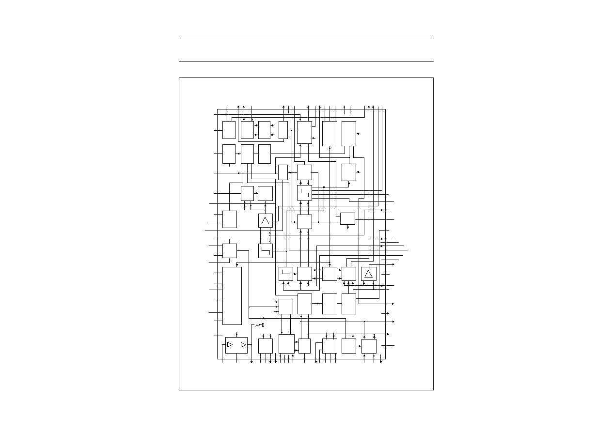
5
BLOCK DIAGRAM
6
PINNING
7
FUNCTIONAL DESCRIPTION
7.1
Oscillators
7.1.1
VCO
7.1.2
PLL
7.1.3
Crystal oscillator
7.2
DAA
7.3
FM signal channel
7.3.1
FM mixer 1
7.3.2
Buffer output for weather band flag
(pin WBFLAG)
7.3.3
FM keyed AGC
7.3.4
FM IF amplifier
7.3.5
FM mixer 2
7.3.6
FM IF2 dynamic selectivity
7.3.7
FM quadrature demodulator
7.3.8
FM MPX soft mute
7.3.9
Adjacent channel detector and threshold
extension
7.3.10
Bandwidth control `active' flag (pin IFBWFLAG)
7.3.11
Bandwidth control monitor voltage (pin V
IFBW
)
7.4
AM signal channel
7.4.1
AM tuner including mixer 1 and mixer 2
7.4.2
AM RF AGC
7.4.3
AM detector
7.4.4
AM noise blanker
7.5
FM and AM level detector
8
LIMITING VALUES
9
THERMAL CHARACTERISTICS
10
DC CHARACTERISTICS
11
AC CHARACTERISTICS
12
I
2
C-BUS PROTOCOL
12.1
I
2
C-bus specification
12.1.1
Data transfer
12.1.2
I
2
C-bus pull-up resistors
12.1.3
Frequency setting
12.1.4
Default settings
12.2
I
2
C-bus protocol
12.2.1
Data transfer mode and IC address
12.2.2
Write mode: data byte 0
12.2.3
Write mode: data byte 1
12.2.4
Write mode: data byte 2
12.2.5
Write mode: data byte 3
12.2.6
Write mode: data byte 4
12.2.7
Write mode: data byte 5
12.2.8
Write mode: data byte 6
12.2.9
Write mode: data byte 7
12.2.10
Read mode: data byte 0
13
TEST AND APPLICATION INFORMATION
14
INTERNAL CIRCUITRY
15
PACKAGE OUTLINE
16
SOLDERING
16.1
Introduction to soldering surface mount
packages
16.2
Reflow soldering
16.3
Wave soldering
16.4
Manual soldering
16.5
Suitability of surface mount IC packages for
wave and reflow soldering methods
17
DATA SHEET STATUS
18
DEFINITIONS
19
DISCLAIMERS
20
PURCHASE OF PHILIPS I
2
C COMPONENTS
2003 Dec 19
3
Philips Semiconductors
Product specification
New In Car Entertainment car radio tuner IC with
Precision Adjacent Channel Suppression (NICE-PACS)
TEA6849H
1
FEATURES
·
FM mixer 1 for conversion of FM RF (65 to 108 MHz
and US weather band) to IF of 10.7 MHz; the mixer
provides inherent image rejection; for European and
US FM band/WB (weather band) the mixer is driven with
a `high' injection Local Oscillator (LO); in Japan
FM band and East Europe FM band the mixer is driven
with a `low' injection LO
·
AM mixer 1 for conversion of AM RF to AM IF1 of
10.7 MHz
·
LC tuner oscillator providing mixer frequencies for
FM mixer and AM mixer 1
·
AM mixer 2 for conversion of AM IF1 to AM IF2 of
450 kHz
·
Crystal oscillator providing mixer frequencies for
AM mixer 2 and FM mixer 2 and reference for
synthesizer PLL, IF count, timing for Radio Data System
(RDS) update and reference frequency for car audio
signal processor ICs
·
Fast synthesizer PLL tuning system with local control for
inaudible RDS updating
·
Timing function for RDS update algorithm and control
signal output for car audio signal processor ICs
(TEA688x, SAA77xx, TEF689x)
·
I
2
C-bus adjustable FM MPX soft mute
·
Digital alignment circuit for bus controlled matching of
oscillator tuning voltage to FM antenna tank circuit
tuning voltage
·
AGC PIN diode drive circuit for FM RF AGC; AGC
detection at FM mixer input; the AGC PIN diode drive
can be activated by the I
2
C-bus as a local function for
search tuning; AGC threshold is a programmable and
keyed function switchable via the I
2
C-bus
·
FM IF linear amplifier with high dynamic input range
·
FM mixer 2 for conversion of FM IF1 to FM IF2 of
450 kHz with inherent image rejection
·
Fully integrated dynamic selectivity and
FM demodulator at IF2; improved sensitivity with
dynamic threshold extension; centre frequency of IF2
selectivity alignment via the I
2
C-bus
·
Level detector for AM and FM with temperature
compensated output voltage; starting point and slope of
level output is programmable via the I
2
C-bus
·
AM cascode AGC stage and RF PIN diode drive circuit;
AGC threshold detection at AM mixer 1 and IF2 AGC
input; threshold for detection at mixer 1 input is
programmable via the I
2
C-bus
·
AM IF2 AGC and demodulator
·
AM AF output switchable to provide AM IF2 for
AM stereo decoder
·
AM noise blanker with detection at IF1 and blanking at
AM IF2
·
Software controlled flag output
·
Buffer output for weather band flag
·
Adjacent channel detector and modulation detector for
instantaneous bandwidth control of the integrated filter
·
Flag and voltage output indicating the actual bandwidth.
2
GENERAL DESCRIPTION
The TEA6849H is a single IC with car radio tuner for AM,
FM and Weather Band (WB) intended for microcontroller
tuning with the I
2
C-bus. It provides the following functions:
·
AM double conversion receiver for LW, MW and SW
(31 m, 41 m and 49 m bands) with IF1 = 10.7 MHz and
IF2 = 450 kHz
·
FM double conversion receiver with integrated image
rejection for IF1 and for IF2 capable of selecting US FM,
US weather, Europe FM, East Europe FM and
Japan FM bands; fully integrated dynamic selectivity at
450 kHz FM IF2; FM demodulator with dynamic
threshold extension; centre frequency alignment of IF2
selectivity via the I
2
C-bus
·
The tuning system includes VCO, crystal oscillator and
PLL synthesizer on one chip.
3
ORDERING INFORMATION
TYPE NUMBER
PACKAGE
NAME
DESCRIPTION
VERSION
TEA6849H
LQFP80
plastic low profile quad flat package; 80 leads; body 12
×
12
×
1.4 mm
SOT315-1

2003 Dec 19
4
Philips Semiconductors
Product specification
New In Car Entertainment car radio tuner IC with
Precision Adjacent Channel Suppression (NICE-PACS)
TEA6849H
4
QUICK REFERENCE DATA
SYMBOL
PARAMETER
CONDITIONS
MIN.
TYP.
MAX.
UNIT
V
DDA(n)
analog supply voltage 1 to 4 and 6
8
8.5
9
V
I
DDA(tot)
sum of analog supply
currents 1 to 4 and 6
FM mode
45
56
67
mA
AM mode
40
50
60
mA
V
DDA5
analog supply voltage 5
4.75
5
5.25
V
I
DDA5
analog supply current 5
FM mode
-
7.4
-
mA
AM mode
-
11
-
mA
V
DDD
digital supply voltage
4.75
5
5.25
V
I
DDD
digital supply current
FM mode
21
26
31
mA
AM mode
22
27
32
mA
f
AM(ant)
AM input frequency
LW
0.144
-
0.288
MHz
MW
0.522
-
1.710
MHz
SW
5.730
-
9.99
MHz
f
FM(ant)
FM input frequency
65
-
108
MHz
f
FM(WB)(ant)
FM weather band input frequency
162.4
-
162.55
MHz
T
amb
ambient temperature
-
40
-
+85
°
C
AM overall system parameters; see Figs 12 and 13
(S+N)/N
signal plus noise-to-noise ratio
m = 0.3; B
AF
= 2.15 kHz
-
59
-
dB
THD
total harmonic distortion
m = 0.8; f
mod
= 1 kHz
-
0.3
-
%
V
sens(rms)
sensitivity (RMS value)
m = 0.3; f
mod
= 1 kHz;
(S+N)/N = 26 dB;
with European dummy
aerial 15 pF/60 pF;
B
AF
= 2.15 kHz
-
45
-
µ
V
FM overall system parameters; see Figs 12 and 13
(S+N)/N
signal plus noise-to-noise ratio
f = 22.5 kHz;
de-emphasis = 50
µ
s;
B
AF
= 300 Hz to 15 kHz
-
63
-
dB
THD
total harmonic distortion
f = 75 kHz;
with 2
×
SFE10.7MS3
-
0.35
-
%
V
sens(rms)
sensitivity (RMS value)
f = 22.5 kHz;
f
mod
= 1 kHz;
(S+N)/N = 26 dB;
de-emphasis = 50
µ
s;
B
AF
= 300 Hz to 15 kHz;
with 75
dummy antenna
-
1.4
2
µ
V