1996 Jan 15
2
Philips Semiconductors
Product specification
Advanced pager receiver
UAA2082
FEATURES
∑
Wide frequency range: VHF, UHF and 900 MHz bands
∑
High sensitivity
∑
High dynamic range
∑
Electronically adjustable filters on chip
∑
Suitable for data rates up to 2400 bits/s
∑
Wide frequency offset and deviation range
∑
Fully POCSAG compatible FSK receiver
∑
Power on/off mode selectable by the chip enable input
∑
Low supply voltage; low power consumption
∑
1-cell battery-low detection circuit
∑
High integration level
∑
Interfaces directly to the PCA5000A, PCF5001 and
PCD5003 POCSAG decoders.
APPLICATIONS
∑
Wide area paging
∑
On-site paging
∑
Telemetry
∑
RF security systems
∑
Low bit-rate wireless data links.
GENERAL DESCRIPTION
The UAA2082 is a high-performance low-power radio
receiver circuit primarily intended for VHF, UHF and
900 MHz pager receivers for wide area digital paging
systems, employing direct FM non-return-to-zero (NRZ)
frequency shift keying (FSK).
The receiver design is based on the direct conversion
principle where the input signal is mixed directly down to
the baseband by a local oscillator on the signal frequency.
Two complete signal paths with signals of 90
∞
phase
difference are required to demodulate the signal.
All channel selectivity is provided by the built-in IF filters.
The circuit makes extensive use of on-chip capacitors to
minimize the number of external components.
The battery monitoring circuit has an external sense input
and a 1.1 V detection threshold for easy operation in a
single-cell supply concept.
The UAA2082 was designed to operate together with the
PCA5000A, PCF5001 or PCD5003 POCSAG decoders,
which contain a digital input filter for optimum call success
rate.
ORDERING INFORMATION
TYPE
NUMBER
PACKAGE
NAME
DESCRIPTION
VERSION
UAA2082H
LQFP32
plastic low profile quad flat package; 32 leads; body 7
◊
7
◊
1.4 mm
SOT358-1
UAA2082U
28 pads
naked die; see Fig.8
1996 Jan 15
4
Philips Semiconductors
Product specification
Advanced pager receiver
UAA2082
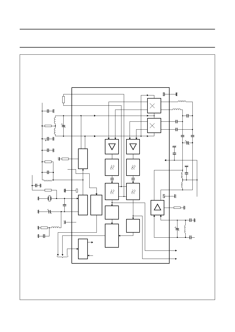
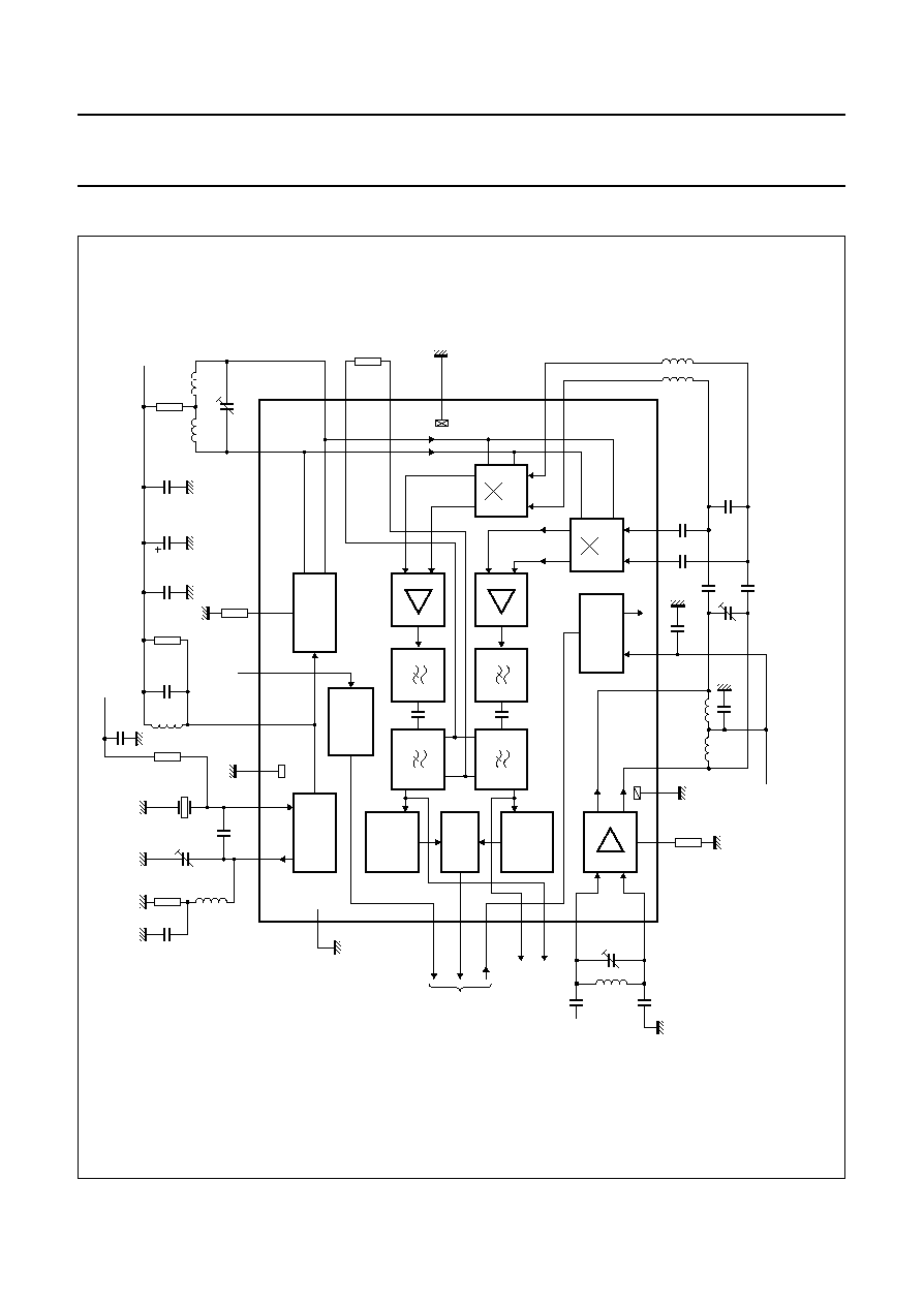
BLOCK DIAGRAMS (173 MHz)
handbook, full pagewidth
MLC222
ACTIVE
FILTER
GYRATOR
FILTER
ACTIVE
FILTER
GYRATOR
FILTER
low noise
amplifier Q
low noise
amplifier I
15
16
18
19
RF pre-amplifier
11
R1
10
8
C3
5 to
20 pF
L1
43
nH
C2
8.2 pF
C1
8.2 pF
BAND GAP
REFERENCE
IF testpoints
TPI
TPQ
5
6
7
GND1
L3
22 nH
L2
22 nH
12
C4 1 nF
C5 1 nF
C10
22 pF
C11
22 pF
C7
8.2 pF
C6
5 to
20 pF
C8
8.2 pF
C9
8.2 pF
L4
150
nH
L5
150
nH
13
14
CRYSTAL
OSCILLATOR
FREQUENCY
MULTIPLIER
V
ref
BLI
RE
to
decoder
3
2
1
TS
C18
1 nF
R5
1.5
k
R6
22
k
L9
560
nH
C16
13 to
50 pF
XTAL
C17
15 pF
C14
1 nF
V
P
V
P
C13
10
µ
F
R7
100
C20
1 nF
26
27
SENSE
28
C15
27 pF
L8
27
nH
GND3
30
31
32
R4
2.2 k
C19
1 nF
UAA2082H
24
25
C12
5 to 20 pF
L7
33 nH
L6
33 nH
R3
1.5 k
R2
47
k
22
21
20
GND2
BATTERY
LOW
INDICATOR
LIMITER
Q
DEMO-
DULATOR
LIMITER
I
DO
MIXER I
MIXER Q
V
P
4
330
V
i(RF)
V
bias(osc)
Fig.1 Block, test and application diagram drawn for LQFP32; f
i(RF)
=
172.941
MHz.
Pins 9, 17, 23 and 29 are not connected.