Document Outline
- 1 FEATURES
- 2 APPLICATIONS
- 3 GENERAL DESCRIPTION
- 4 ORDERING INFORMATION
- 5 BLOCK DIAGRAM
- 6 PINNING
- 7 FUNCTIONAL DESCRIPTION
- 7.1 Control
- 7.2 OFF mode
- 7.3 SHUTDOWN mode
- 7.4 SLOW CHARGE mode
- 7.5 FAST CHARGE mode
- 7.6 REVERSE mode
- 7.7 REVERSE and SLOW CHARGE mode
- 7.8 REVERSE and FAST CHARGE mode
- 8 LIMITING VALUES
- 9 THERMAL CHARACTERISTICS
- 10 CHARACTERISTICS
- 11 APPLICATION INFORMATION
- 11.1 Application diagram
- 11.2 Soft switching
- 11.3 Current measurement possibility
- 11.4 Drop voltage dependence
- 12 PACKAGE OUTLINE
- 13 SOLDERING
- 13.1 Introduction to soldering surface mount packages
- 13.2 Reflow soldering
- 13.3 Wave soldering
- 13.4 Manual soldering
- 13.5 Suitability of surface mount IC packages for wave and reflow soldering methods
- 14 DATA SHEET STATUS
- 15 DEFINITIONS
- 16 DISCLAIMERS
DATA SHEET
Product specification
2003 Oct 01
INTEGRATED CIRCUITS
UBA2007
Charge switch

2003 Oct 01
2
Philips Semiconductors
Product specification
Charge switch
UBA2007
CONTENTS
1
FEATURES
2
APPLICATIONS
3
GENERAL DESCRIPTION
4
ORDERING INFORMATION
5
BLOCK DIAGRAM
6
PINNING
7
FUNCTIONAL DESCRIPTION
7.1
Control
7.2
OFF mode
7.3
SHUTDOWN mode
7.4
SLOW CHARGE mode
7.5
FAST CHARGE mode
7.6
REVERSE mode
7.7
REVERSE and SLOW CHARGE mode
7.8
REVERSE and FAST CHARGE mode
8
LIMITING VALUES
9
THERMAL CHARACTERISTICS
10
CHARACTERISTICS
11
APPLICATION INFORMATION
11.1
Application diagram
11.2
Soft switching
11.3
Current measurement possibility
11.4
Drop voltage dependence
12
PACKAGE OUTLINE
13
SOLDERING
13.1
Introduction to soldering surface mount
packages
13.2
Reflow soldering
13.3
Wave soldering
13.4
Manual soldering
13.5
Suitability of surface mount IC packages for
wave and reflow soldering methods
14
DATA SHEET STATUS
15
DEFINITIONS
16
DISCLAIMERS

2003 Oct 01
3
Philips Semiconductors
Product specification
Charge switch
UBA2007
1
FEATURES
�
Very low ohmic charge switch (0.25
) with soft
switching and adjustable current limitation
�
Very low ohmic reverse switch (0.25
) with built-in
current limitation
�
130 mA pre-charge current
�
Battery overvoltage and undervoltage protection
�
Charger overvoltage protection of up to +20 V and
reverse polarity protection down to
-
20 V
�
On-chip thermal protection
�
Charger detection
�
Built-in current sensing
�
Small 3
�
3 mm HVSON10 package with excellent
thermal properties
�
The UBA2007 is qualified according to the
IEC 61000-4-2 standard for ESD performance.
2
APPLICATIONS
�
Charging circuits.
3
GENERAL DESCRIPTION
The UBA2007 is an intelligent charge switch IC for pulse
mode charging applications. With its integrated low ohmic
power switch it is designed for charging of 1-cell Li-Ion or
3-cell NiMH batteries in either a pre-charge or fast charge
mode. The reverse mode of the UBA2007 allows the
supply of accessories connected to the charger pin.
Several integrated safety mechanisms such as current
limitation, overvoltage protection, thermal protection and
ESD guarantee fail-safe operation.
4
ORDERING INFORMATION
TYPE NUMBER
PACKAGE
NAME
DESCRIPTION
VERSION
UBA2007TK/N2
HVSON10
plastic thermal enhanced very thin small outline package;
no leads; 10 terminals; body 3
�
3
�
0.85 mm
SOT650-1
2003 Oct 01
4
Philips Semiconductors
Product specification
Charge switch
UBA2007
5
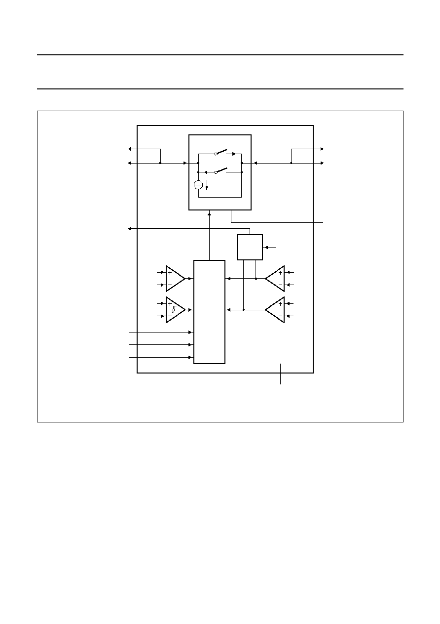
BLOCK DIAGRAM
handbook, full pagewidth
MRC312
reverse mode
DIGITAL
CONTROL
MUX
fast charge mode
slow charge mode
RLIMF
8
1
fast charge mode
current limit
BAT
6 V
temp
Tmax
CHG
BAT
CHG
2.5 V
REVMOD
CURMOD
10
SWMOD
9
REVMOD
2
UBA2007
VSS
3
BAT
BAT
5
4
CHG
CHG
7
6
CHGOK_N
Fig.1 Block diagram.

2003 Oct 01
5
Philips Semiconductors
Product specification
Charge switch
UBA2007
6
PINNING
SYMBOL
PIN
DESCRIPTION
RLIMF
1
FAST CHARGE mode current limiting resistor; output current source
REVMOD
2
REVERSE mode control; see Table 1 for operating modes; digital input
V
SS
3
ground
BAT
4
battery pin; power input/output
BAT
5
battery pin; power input/output
CHG
6
charger input/REVERSE mode output; power input/output
CHG
7
charger input/REVERSE mode output; power input/output
CHGOK_N
8
charger detection output; if REVMOD is LOW, the output is in high-impedance state when
V
CHG
< 2.5 V; if REVMOD is HIGH the output is in high-impedance state when V
CHG
< V
BAT
;
open drain output
SWMOD
9
PWM mode input; see Table 1 for operating modes; digital input 160 k
pull-down
CURMOD
10
charge mode input; see Table 1 for operating modes; digital input 160 k
pull-down
handbook, halfpage
MRC313
terminal 1
index area
CURMOD
REVMOD
RLIMF
SWMOD
VSS
BAT
CHG
BAT
CHG
CHGOK_N
UBA2007TK
1
10
2
9
3
8
4
7
5
6
This diagram is a bottom view
For mechanical specification of HVSON10 package, see Chapter 12.
Fig.2 Pin configuration.