Philips Semiconductors
Preliminary specification
UCB1100
Advanced modem/audio analog front-end
Version 1.2
2
1998 May 08
GENERAL DESCRIPTION
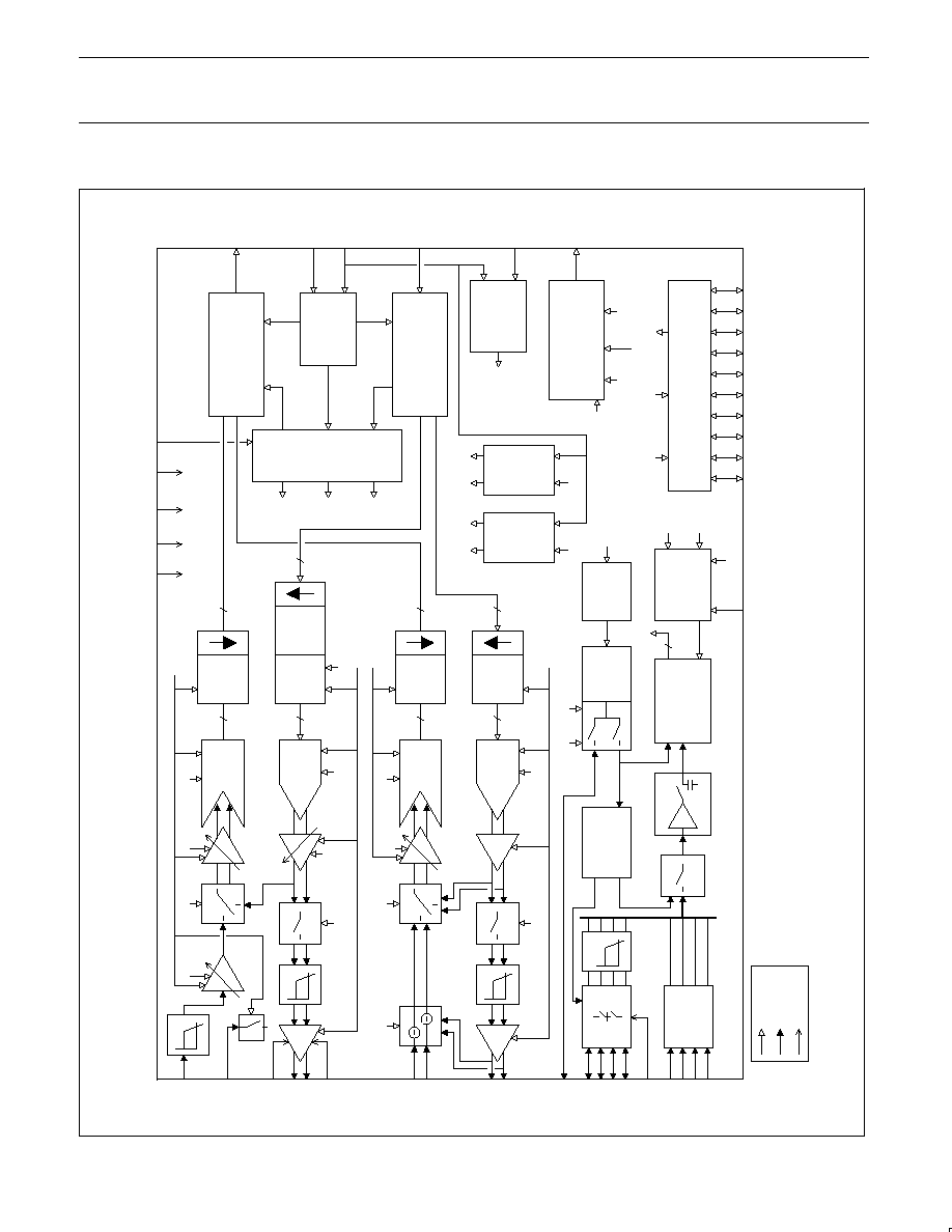
The UCB1100 is a single chip, integrated mixed signal audio and
telecom codec. The single channel audio codec is designed for
direct connection of a microphone and speaker. The built-in telecom
codec can directly be connected to a DAA and supports high speed
modem protocols. The incorporated 10 bit analogue to digital
converter and the touch screen interface provides complete control
and readout of a connected 4 wire resistive touch screen. The 10
additional general purpose I/O pins provides programmable inputs
and/or outputs to the system.
The UCB1100 has a serial interface bus (SIB) intended to
communicate to the system controller. Both the codec input and
output data and the control register data is multiplexed on this SIB
interface.
APPLICATIONS
∑
Personal Intelligent Communicators
∑
Personal Digital Assistants (PDA)
∑
Screen phones
∑
Smart Phone and smart Fax
∑
Intelligent Communicators
KEY FEATURES
∑
48-pin LQFP (SOT313-2) small body SMD package and low
external component count result in minimal PCB space
requirement.
∑
A 12-bit sigma delta audio codec with programmable sample rate,
input and output voltage levels, capable of connecting directly to
speaker and microphone, including digitally controlled mute,
loopback and clip detection functions
∑
A 14-bit sigma delta telecom codec with programmable sample
rate, including digitally controlled input voltage level, mute,
loopback and clip detection functions. The telecom codec is
intended for direct connection to a DAA (digital access
arrangement) and includes a built-in sidetone suppression circuit.
∑
A complete 4 wire resistive touch screen interface circuit
supporting position, pressure and plate resistance measurements.
∑
A 10-bit successive approximation ADC with internal track and
hold circuit and analogue multiplier for touch screen readout and
monitoring of four external high voltage (7.5V) analogue voltages.
∑
A high speed, 4 wire serial interface data bus (SIB) for
communication to system controller.
∑
A 3.3V supply voltage and built in power saving modes make the
UCB1100 optimal for portable and battery powered applications.
TABLE OF CONTENTS
GENERAL DESCRIPTION
2
. . . . . . . . . . . . . . . . . . . . . . . . . . . . . . . . .
APPLICATIONS
2
. . . . . . . . . . . . . . . . . . . . . . . . . . . . . . . . . . . . . . . . . . .
KEY FEATURES
2
. . . . . . . . . . . . . . . . . . . . . . . . . . . . . . . . . . . . . . . . . .
TABLE OF CONTENTS
2
. . . . . . . . . . . . . . . . . . . . . . . . . . . . . . . . . . . .
1.0
FUNCTIONAL BLOCK DIAGRAM
3
. . . . . . . . . . . . . . . . . . . . .
2.0
ORDERING INFORMATION
4
. . . . . . . . . . . . . . . . . . . . . . . . . .
3.0
ABSOLUTE MAXIMUM RATINGS
4
. . . . . . . . . . . . . . . . . . . . .
4.0
DC ELECTRICAL CHARACTERISTICS
5
. . . . . . . . . . . . . . . .
5.0
PINOUT
6
. . . . . . . . . . . . . . . . . . . . . . . . . . . . . . . . . . . . . . . . . . . .
5.1
PINLIST
7
. . . . . . . . . . . . . . . . . . . . . . . . . . . . . . . . . . . . . .
6.0
FUNCTIONAL DESCRIPTION
8
. . . . . . . . . . . . . . . . . . . . . . . .
6.1
AUDIO CODEC
8
. . . . . . . . . . . . . . . . . . . . . . . . . . . . . . .
6.1.1 AUDIO INPUT SPECIFICATIONS
10
. . . . . . . .
6.1.2 AUDIO OUTPUT SPECIFICATIONS
11
. . . . . . .
6.2
TELECOM CODEC
12
. . . . . . . . . . . . . . . . . . . . . . . . . . .
6.2.1 TELECOM INPUT SPECIFICATIONS
14
. . . . .
6.2.2 TELECOM OUTPUT SPECIFICATIONS
15
. . .
6.3
TOUCH SCREEN MEASUREMENT MODES
16
. . . .
6.3.1 POSITION MEASUREMENT
16
. . . . . . . . . . . . .
6.3.2 PRESSURE MEASUREMENT
16
. . . . . . . . . . .
6.3.3 PLATE RESISTANCE MEASUREMENT
16
. . .
6.4
TOUCH SCREEN INTERFACE
17
. . . . . . . . . . . . . . . . .
6.4.1 TOUCH SCREEN SPECIFICATIONS
18
. . . . .
6.5
10 BIT ADC.
19
. . . . . . . . . . . . . . . . . . . . . . . . . . . . . . . . .
6.5.1 SPECIFICATION OVERVIEW
21
. . . . . . . . . . . .
6.6
ON CHIP REFERENCE CIRCUIT
21
. . . . . . . . . . . . . .
6.6.1 SPECIFICATION OVERVIEW
21
. . . . . . . . . . . .
6.7
SERIAL INTERFACE BUS
22
. . . . . . . . . . . . . . . . . . . . .
6.7.1 SIB DATA FORMAT
23
. . . . . . . . . . . . . . . . . . . . .
6.7.2 CODEC DATA TRANSFER
24
. . . . . . . . . . . . . .
6.7.3 CONTROL REGISTER DATA TRANSFER
26
.
6.7.4 AC ELECTRICAL CHARACTERISTICS
27
. . .
6.8
GENERAL PURPOSE I/Os
27
. . . . . . . . . . . . . . . . . . . .
6.9
INTERRUPT GENERATION
27
. . . . . . . . . . . . . . . . . . .
6.10
RESET CIRCUITRY
28
. . . . . . . . . . . . . . . . . . . . . . . . . .
7.0
MISCELLANEOUS
29
. . . . . . . . . . . . . . . . . . . . . . . . . . . . . . . . .
7.1
POWER ROUTING STRATEGY
29
. . . . . . . . . . . . . . . .
8.0
CONTROL REGISTER OVERVIEW
30
. . . . . . . . . . . . . . . . . .
9.0
PACKAGE OUTLINES
34
. . . . . . . . . . . . . . . . . . . . . . . . . . . . . .
9.1
PACKAGE OUTLINE LQFP48
34
. . . . . . . . . . . . . . . . . .
10.0
DEFINITIONS
36
. . . . . . . . . . . . . . . . . . . . . . . . . . . . . . . . . . . . .
Philips Semiconductors
Preliminary specification
UCB1100
Advanced modem/audio analog front-end
1998 May 08
4
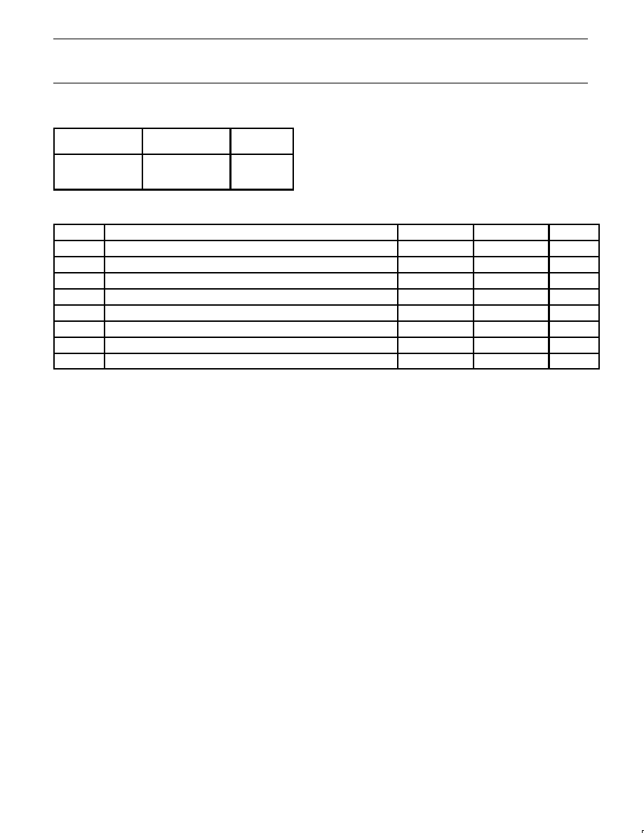
2.0
ORDERING INFORMATION
¡¡¡¡¡¡
¡
¡¡¡¡
¡
¡¡¡¡¡¡
DESCRIPTION
¡¡¡¡¡¡¡
¡
¡¡¡¡¡
¡
¡¡¡¡¡¡¡
ORDERING
CODE
¡¡¡¡¡
¡
¡¡¡
¡
¡¡¡¡¡
PACKAGE
DRAWING
¡¡¡¡¡¡
¡
¡¡¡¡
¡
¡¡¡¡¡¡
Plastic low profile
quad flat package;
48 leads
¡¡¡¡¡¡¡
¡
¡¡¡¡¡
¡
¡¡¡¡¡¡¡
UCB1100LP/X3
¡¡¡¡¡
¡
¡¡¡
¡
¡¡¡¡¡
SOT313-2
3.0
ABSOLUTE MAXIMUM RATINGS
SYMBOL
PARAMETER
MIN
MAX
UNIT
V
DDMAX
Supply voltage
≠0.5
5.0
V
V
IMAX
DC input voltage, except AD0≠3 inputs
≠0.5
V
DD
+0.5
V
V
ADMAX
DC input voltage AD0≠3 inputs
≠0.5
8.5
V
V
OMAX
DC output voltage
≠0.5
V
DD
+0.5
V
I
IKMAX
DC diode input current, all inputs
10
mA
I
OKMAX
DC diode output current
10
mA
I
OLMAX
Continuous output current, digital outputs
4
mA
T
stg
Storage temperature
≠55
150
∞
C
NOTES:
1. Stresses above those listed under Absolute Maximum Ratings may cause permanent damage to the device. This is a stress rating only and
functional operation of the device at these or any conditions other than those described in the Absolute Maximum Rating section of this
specification is not implied.
2. This product includes circuitry specially designed for the protection of its internal devices from damaging effects of excessive static charge.
Nonetheless, it is suggested that conventional precautions be taken to avoid submitting the UCB1100 to conditions exceeding the maximum
ratings.
3. Parameters are valid over the operating ambient temperature unless otherwise specified. All voltages are with respect to the V
SSD
pin,
unless otherwise noted.
Philips Semiconductors
Preliminary specification
UCB1100
Advanced modem/audio analog front-end
1998 May 08
5
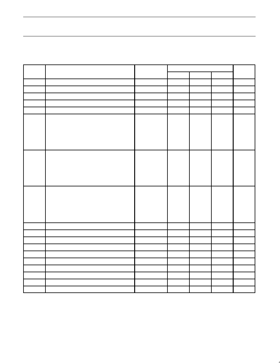
4.0
DC ELECTRICAL CHARACTERISTICS
T
amb
= 0
∞
C to 70
∞
C, V
SSD
= V
SSA1
= V
SSA2
= V
SSA3
= 0V, sibclk = 10MHz, audio_divisor = 12, telecom_divisor = 40.
Voltage with respect to the V
SSD
pin, unless otherwise specified.
SYMBOL
PARAMETER
NOTES
LIMITS
UNIT
SYMBOL
PARAMETER
NOTES
MIN
TYP
MAX
UNIT
V
DDD
digital supply voltage
3.0
3.3
3.6
V
V
DDA1
analogue supply voltage (excl.speaker driver)
3.0
3.3
3.6
V
V
DDA2
analogue supply voltage (speaker driver only)
3.0
3.3
3.6
V
V
SSA2
analogue ground voltage wrt. V
SSD
≠0.4
0
0.4
V
V
SSA3
analogue ground voltage wrt V
SSD
≠0.4
0
0.4
V
I
DDD
digital supply current,
Note 1
full functionality
19
mA
only audio codec activated
17
mA
only telecom codec activated
19
mA
only touch screen activated
15
mA
only adc activated
15
mA
no functions activated, sibclk stopped
10
µ
A
I
DDA1
analogue supply current,
Note 1, Note 2
full functionality
3.8
mA
only audio codec activated
1.5
mA
only telecom codec activated
1.7
mA
only touch screen activated
0.4
mA
only adc activated
0.5
mA
no analogue functions activated
<10
µ
A
I
DDA2
total speaker driver supply current
Note 1, Note 2
full functionality
0.2
mA
only audio codec activated
0.2
mA
only telecom codec activated
10
µ
A
only touch screen activated
10
µ
A
only adc activated
10
µ
A
no analogue functions activated
10
µ
A
V
TSCB
touch screen bias voltage
1.8
V
I
TSCB
maximum touch screen bias current
10
mA
V
ADFS
full scale voltage ad0≠ad3 inputs
7.5
V
V
TSFS
full scale input touch screen inputs
7.5
V
V
IL
input low voltage
≠0.5
0.3*V
DDD
V
V
IH
input high voltage
0.7*V
DDD
V
DDD
+0.5
V
V
OL
output low voltage
I
OL
=2mA
0.2*V
DDD
V
V
OH
output high voltage
I
OH
=2mA
0.8*V
DDD
V
f
SIBCLK
clock frequency
0
10
15
MHz
T
amb
Operating Ambient Temperature
0
70
∞
C
NOTES:
1. Indicative value only. Value will be frozen following silicon measurements.
2. Excluding connected touch screen and speaker load currents.