2000 Feb 18
2
Philips Semiconductors
Preliminary specification
96 kHz IEC 958 audio DAC
UDA1351H
CONTENTS
1
FEATURES
1.1
General
1.2
Control
1.3
IEC 958 input
1.4
Digital output and input interfaces
1.5
Digital sound processing and DAC
2
APPLICATIONS
3
GENERAL DESCRIPTION
4
QUICK REFERENCE DATA
5
ORDERING INFORMATION
6
BLOCK DIAGRAM
7
PINNING
8
FUNCTIONAL DESCRIPTION
8.1
Operating modes
8.2
Clock regeneration and lock detection
8.3
Mute
8.4
Auto mute
8.5
Data path
8.5.1
IEC 958 input
8.5.2
Digital data output and input interface
8.5.3
Audio feature processor
8.5.4
Interpolator
8.5.5
Noise shaper
8.5.6
The Filter Stream DAC (FSDAC)
8.6
Control
8.6.1
Static pin control mode
8.6.2
L3 control mode
8.7
L3 interface
8.7.1
General
8.7.2
Device addressing
8.7.3
Register addressing
8.7.4
Data write mode
8.7.5
Data read mode
8.7.6
Initialization string
8.7.7
Overview of L3 interface registers
8.7.8
Writable registers
8.7.9
Readable registers
9
LIMITING VALUES
10
THERMAL CHARACTERISTICS
11
CHARACTERISTICS
12
TIMING CHARACTERISTICS
13
APPLICATION INFORMATION
14
PACKAGE OUTLINE
15
SOLDERING
15.1
Introduction to soldering surface mount
packages
15.2
Reflow soldering
15.3
Wave soldering
15.4
Manual soldering
15.5
Suitability of surface mount IC packages for
wave and reflow soldering methods
16
DEFINITIONS
17
LIFE SUPPORT APPLICATIONS

2000 Feb 18
3
Philips Semiconductors
Preliminary specification
96 kHz IEC 958 audio DAC
UDA1351H
1
FEATURES
1.1
General
�
2.7 to 3.6 V power supply
�
Integrated digital filter and Digital-to-Analog
Converter (DAC)
�
Master-mode data output interface for off-chip sound
processing
�
256f
s
system clock output
�
20-bit data-path in interpolator
�
High performance
�
No analog post filtering required for DAC
�
Supports sampling frequencies from 28 up to 100 kHz
�
The UDA1351H is fully pin and function compatible with
the UDA1350AH.
1.2
Control
�
Controlled either by means of static pins or via the
L3 microcontroller interface.
1.3
IEC 958 input
�
On-chip amplifier for converting IEC 958 input to CMOS
levels
�
Selectable IEC 958 input channel, one out of two
�
Lock indication signal available on pin LOCK
�
Lock indication signal combined on-chip with the Pulse
Code Modulation (PCM) status bit; in case non-PCM
has been detected pin LOCK indicates out-of-lock
�
Key channel-status bits available via L3 interface (lock,
pre-emphasis, audio sample frequency, 2 channel PCM
indication and clock accuracy).
1.4
Digital output and input interfaces
�
When the UDA1351H is clock master of the data output
interfaces:
� BCKO and WSO signals are output
� I
2
S-bus or LSB-justified 16, 20 and 24 bits formats
are supported.
�
When the UDA1351H is clock slave of the data input
interface:
� BCK and WS signals are input
� I
2
S-bus or LSB-justified 16, 20 and 24 bits formats
are supported.
1.5
Digital sound processing and DAC
�
Pre-emphasis information of IEC 958 input bitstream
available in L3 interface register and on pins
�
Automatic de-emphasis when using IEC 958 input with
32.0, 44.1 and 48.0 kHz audio sample frequencies
�
Soft mute by means of a cosine roll-off circuit selectable
via pin MUTE or the L3 interface
�
Interpolating filter (f
s
to 128f
s
) by means of a cascade of
a recursive filter and a FIR filter
�
Third-order noise shaper operating at 128f
s
generates
bitstream for the DAC
�
Filter stream digital-to-analog converter.
2
APPLICATIONS
�
Digital audio systems.
3
GENERAL DESCRIPTION
The UDA1351H is a single chip IEC 958 audio decoder
with an integrated stereo digital-to-analog converter
employing bitstream conversion techniques.
Besides the UDA1351H, which is the full featured version
in QFP44 package, there also exists the UDA1351TS.
The UDA1351TS has IEC 958 input to the DAC only and
is in SSOP28 package.
The UDA1351H can operate in various operating modes:
�
IEC 958 input to the DAC including on-chip signal
processing
�
IEC 958 input via the digital data output interface to the
external Digital Signal Processor (DSP)
�
IEC 958 input to the DAC and a DSP
�
IEC 958 input via a DSP to the DAC including on-chip
signal processing
�
External source data input to the DAC including on-chip
signal processing.
2000 Feb 18
4
Philips Semiconductors
Preliminary specification
96 kHz IEC 958 audio DAC
UDA1351H
The IEC 958 input audio data including the accompanying
pre-emphasis information is available on the output data
interface.
A lock indication signal is available on pin LOCK indicating
that the IEC 958 decoder is locked.
By default the DAC output and the data output interface
are muted when the decoder is out-of-lock. However, this
setting can be overruled in the L3 control mode.
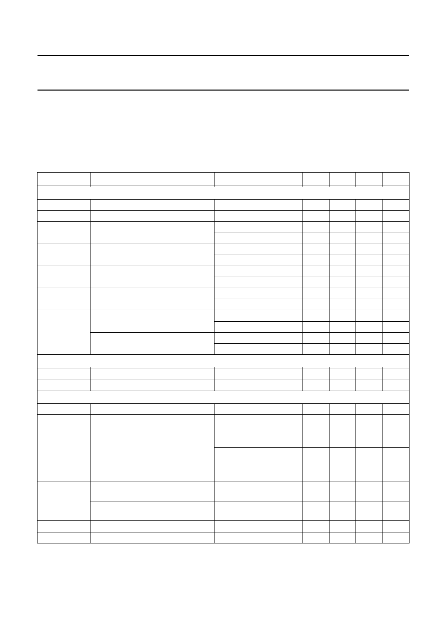
4
QUICK REFERENCE DATA
Note
1. The DAC output voltage is proportionally to the DAC power supply voltage.
SYMBOL
PARAMETER
CONDITIONS
MIN.
TYP.
MAX.
UNIT
Supplies
V
DDD
digital supply voltage
2.7
3.0
3.6
V
V
DDA
analog supply voltage
2.7
3.0
3.6
V
I
DDA(DAC)
analog supply current of DAC
power-on
-
8.0
-
mA
power-down
-
750
-
�
A
I
DDA(PLL)
analog supply current of PLL
at 48 kHz
-
0.7
-
mA
at 96 kHz
-
1.0
-
mA
I
DDD(C)
digital supply current of core
at 48 kHz
-
16.0
-
mA
at 96 kHz
-
24.5
-
mA
I
DDD
digital supply current
at 48 kHz
-
2.0
-
mA
at 96 kHz
-
3.0
-
mA
P
power consumption at 48 kHz
DAC in playback mode
-
80
-
mW
DAC in Power-down mode
-
58
-
mW
power consumption at 96 kHz
DAC in playback mode
-
109
-
mW
DAC in Power-down mode
-
87
-
mW
General
t
rst
reset active time
-
250
-
�
s
T
amb
ambient temperature
-
40
-
+85
�
C
Digital-to-analog converter
V
o(rms)
output voltage (RMS value)
note 1
-
900
-
mV
(THD + N)/S
total harmonic distortion-plus-noise to
signal ratio
f
i
= 1.0 kHz tone at 48 kHz
at 0 dB
-
-
90
-
85
dB
at
-
40 dB; A-weighted
-
-
60
-
55
dB
f
i
= 1.0 kHz tone at 96 kHz
at 0 dB
-
-
85
-
80
dB
at
-
40 dB; A-weighted
-
-
58
-
53
dB
S/N
signal-to-noise ratio at 48 kHz
f
i
= 1.0 kHz tone;
code = 0; A-weighted
95
100
-
dB
signal-to-noise ratio at 96 kHz
f
i
= 1.0 kHz tone;
code = 0; A-weighted
95
100
-
dB
cs
channel separation
f
i
= 1.0 kHz tone
-
96
-
dB
V
o
unbalance of output voltages
f
i
= 1.0 kHz tone
0.4
0.1
-
dB