16
Cooled OEM Modules
w w w. a d va n c e d p h o t o n i x . c o m
Electro-Optical Characteristics
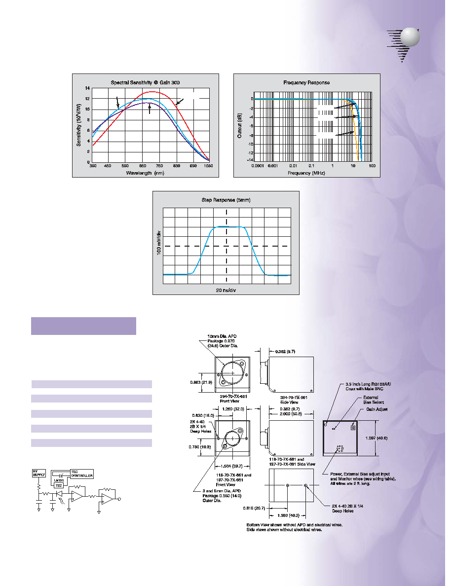
All specifications apply when APD is at 0∫C with a gain of 300 and a load resistance of 50 ohms.
Part
Number
118-70-73-661
118-70-74-661
118-70-72-661
197-70-73-661
197-70-74-661
197-70-72-661
394-70-73-661
394-70-74-661
394-70-72-661
APD
Spectral
Enhancement
UV
Blue
Red/IR
UV
Blue
Red/IR
UV
Blue
Red/IR
APD
Diameter
(mm)
3
5
10
Frequency
High Cutoff
Typ
Min
(MHz) (MHz)
14
12
14
12
11
10
Sensitivity
@ 1 MHz
Typical*
(10
5
V/W)
5.5
9.5
13.5
5.5
9.5
13.5
5.5
9.5
13.5
NEP
Typical*
(pW/ Hz)
0.12
0.065
0.045
0.17
0.095
0.065
0.35
0.21
0.15
Feedback
Resistance
(k )
20±1%
Output
Offset
Typ
Max
(mV) (mV)
±1
±5
Output
Impedance
( )
50
Linear
Output
Swing
(V)
+1
Output
Stability
Typical
(%/∫C)
0.15
Current Consumption
+12V±1V Supply -12V±1V Supply +5V ±0.25V Supply
Typ
Max
Typ
Max
Typ
Max
(mA)
(mA)
(mA)
(mA)
(A)
(A)
120
220
30
50
0.8
1.9
Absolute Maximum Ratings
APD Active
Diameter
(mm)
3
5
10
Continuous Incident
Light Intensity
APD gain =200
=675nm (µW)
0.6
.75
1.5
APD Gain @
23∫C
=675nm
350
Ambient
Operating
Temp.
(∫C)
0 to +40
Storage
Temp.
(∫C)
-40 to +70
Supply
Voltage
(V)
±13 +6
HV bias/APD gain control realized by potentiometer located on backside of the module or remote 0 to +5V analog pro-
gramming configured by jumper located on backside of the module.
Remote HV control ratio: 404 V per 1V (typical).
HV monitor ratio: 404 V per 1V (typical).
Temperature monitor output is 10mV/∫K. (See National Semiconductor data sheet for LM335 temperature sensor)
Devices must be mounted to a heat sink with TEC on.
Recommended load on amplifier output is from 50 ohms to 1 Mohm.
Modules can be modified or customized by Advanced Photonix to meet individual customer requirements.
Operating beyond these limits may cause permanent damage to the device.
* Sensitivity and NEP for UV, Blue, and Red/IR specified at wavelengths of 350nm, 500nm and 750nm, respectively.

