
Subminiature Automotive PCB Power Relay
FEATURES
Subminiature design
1 A (SPST NO) and 1 C (SPDT) contact forms available
Larger contact gap available for heavy motor loads
Contact switching capacity up to 60 Amps
85 degrees C operating temperature
Industry standard 1/2 size terminal layout
PC236A
Max. Switching Voltage
16 VDC
1 Form A or 1 Form C
CONTACT RATINGS
CHARACTERISTICS
Operate Time
10 ms. typical
Release Time
Insulation Resistance
5 ms. typical
100 megohms min, at 500VDC, 50%RH
Dielectric Strength
1250 Vrms, 1 min. between coil and contacts
Shock Resistance
10 g, 11ms, functional; 100 g, destructive
Vibration Resistance
DA 1.5 mm, 10 - 55 Hz
Power Consumption
Standard: 0.6 W; Large Gap: 0.8 W
Ambient Temperature Range
-30 to 85 degrees C operating, -40 to 100 storage
Weight
6 grams approx.
Sales: Call Toll Free (888)997-3933 Fax (818) 342-5296 email: pickerwest@sbcglobal.net URL: pickercomponents.com
3220 Commander Drive, Suite 102, Carrollton, Texas 75006
PC236A Rev B 4-13-04
PAGE 1
Sealed, immersion cleanable
CONTACT DATA
Material
Initial Contact Resistance
Service Life
Mechanical
Electrical
AgSnOInO (Silver Tin Oxide Indium Oxide)
100 milliohms max @ 0.1A, 6VDC
1 X 10
7
1 X 10
5
Operations
Operations
SPST NO or SPDT
Contact Form
Max Switching Current
Break 20 Amps
Make 60 Amps
35 A for 10 Min; 25 A for 1 hr.
AgNiO 15 (Silver Nickel Oxide 15%)
Max. Continuous Current
Minimum Load
0.1 A @ 12 VDC
Drop Resistance
1 Meter height drop on concrete
ORDERING INFORMATION
Example:
PC236A
Model
-12
Coil Voltage
Insulation System
-1C
Nil: Class B (125 degrees C); F: Class F (155 degrees C)
Contact Form
F
Nil: Standard; G: Large Gap
Contact Gap
-G
1A or 1C
PC236A
PC236A
COIL DATA
Coil Voltage
6
9
12
Resistance ohms
Must Operate
Voltage Max.
(VDC)
Must Release
Voltage Min.
(VDC)
60
135
240
960
3.6
5.4
7.3
14.4
0.6
0.9
1.2
2.4
Sales: Call Toll Free (888) 997-3933 Fax (818) 342-5296 email: pickerwest@sbcglobal.net URL: pickercomponents.com
3220 Commander Drive, Suite 102, Carrollton, Texas 75006
PAGE 2
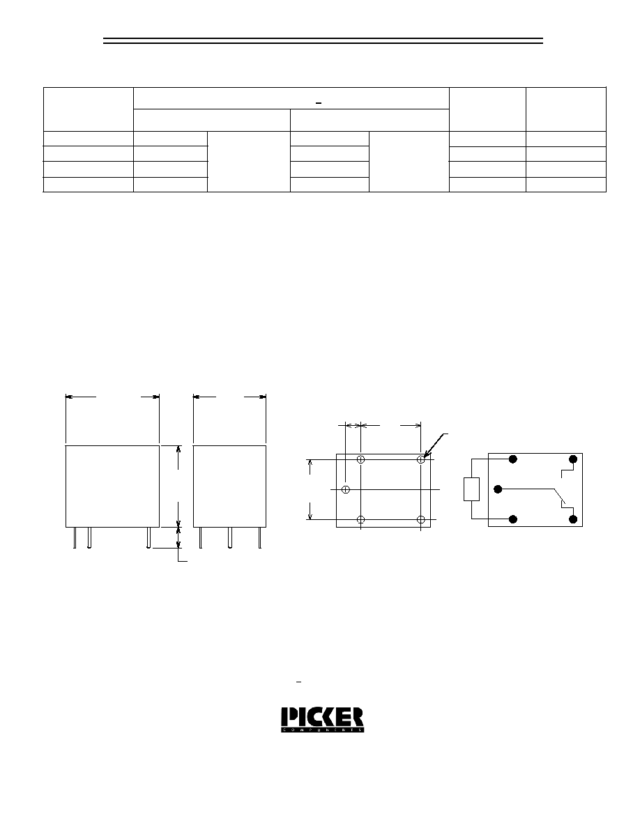
Tolerances + .010 unless otherwise noted
Notes:
Contact Form C shown
On Contact Forms A & B Unused Pins are Omitted
Dimensions in Inches (millimeters)
Side View
End View
Bottom View
PC Board Layout
Wiring Diagram
24
+ 10%
Standard Coil
Large Gap
45
100
180
720
0.6 W
0.8 W
Drawings are 2X actual size
(10.0)
.393
(10.2)
.402
(2.5)
.10
(12.3)
.484
(15.7)
.618
(13.7)
.539
(3.5)
.138
.051 Dia. Typ.
(1.3)