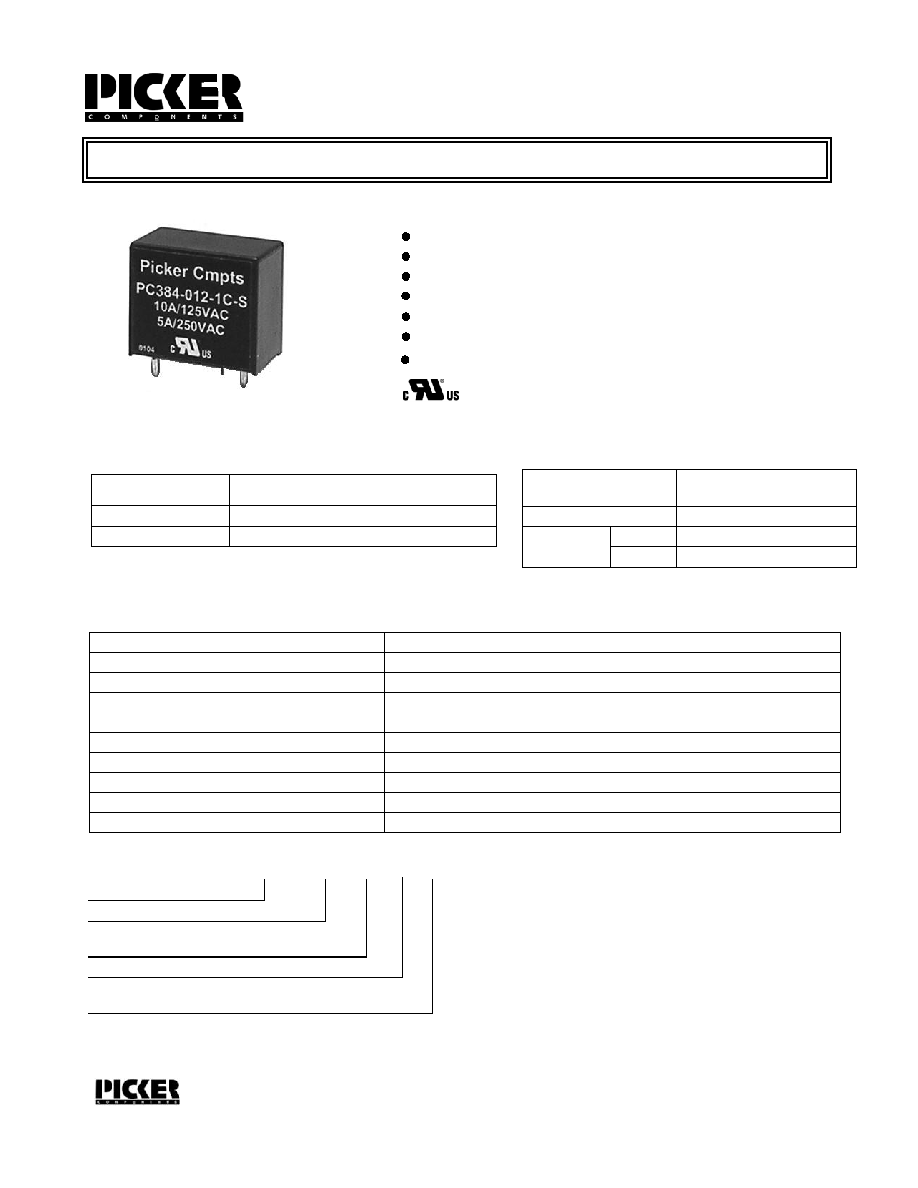
10 Amp Minature PCB Power Relay
FEATURES
10 Amp continous contact capacity
1A or 1C contact form
Class "B" insulation standard
2 KV dielectric between coil and contacts
Class "F" insulation available
PC384
Load Type
General Use
10 Amps @ 125 VAC, 5 Amps @ 250 VAC
All Forms
UL/CSA RATINGS
CHARACTERISTICS
Operate Time
10 ms. Max.
Release Time
Insulation Resistance
4 ms. Max.
250 megohms min, at 500VDC, 50%RH
Dielectric Strength
2000 Vrms, 1 min. between coil and contacts
Shock Resistance
10 g, 11ms, functional; 100 g, destructive
Vibration Resistance
DA 1.5 mm, 10 - 55 Hz
Power Consumption
.36 W
Ambient Temperature Range
-25 to 70 C operating for class B, -40 to 130 C storage
Weight
8.6 grams approx.
Sales: Call Toll Free (888)997-3933 Fax (818) 342-5296 email: pickerwest@sbcglobal.net URL: pickercomponents.com
3220 Commander Drive, Suite 102, Carrollton, Texas 75006
PC384 Rev B 4-6-04
PAGE 1
Sealed, immersion cleanable
CONTACT DATA
Material
Initial Contact Resistance
Service Life
Mechanical
Electrical
AgSnO (Silver Tin Oxide)
50 milliohms max @ 0.1A, 6VDC
1 X 10
7
1 X 10
5
Operations
Operations
All Contacts
Max Switching Power
1250 VA, 280W
750 Vrms, 1 min. between open contacts
File # E86876
AgCdO (Silver Cadmium Oxide)
4KV surge voltage
ORDERING INFORMATION
Example:
PC384
Model
-1C
Contact Form
1A, 1C
-12
Enclosure
S: Sealed; C: Flux Free
Coil Voltage
S

PC384
PC384
Sales: Call Toll Free (888) 997-3933 Fax (818) 342-5296 email: pickerwest@sbcglobal.net URL: pickercomponents.com
3220 Commander Drive, Suite 102, Carrollton, Texas 75006
PAGE 2
Dimensions in Inches (millimeters)
Side View
End View
COIL DATA
Coil Voltage
5
6
12
18
24
Resistance
ohms + 10%
Must Operate
Voltage Max.
(VDC)
Must Release
Voltage Min.
(VDC)
Continuous
Voltage Max.
(VDC)
25
69
100
400
900
1600
3.5
4.2
8.4
12.6
16.8
0.5
0.6
1.2
1.8
2.4
5.5
6.6
13.2
19.8
26.4
_
Note: Custom coil voltages within the ranges shown are available on special order.
3
2.1
0.3
3.3
9
225
6.3
0.9
9.9
(15.0)
.591
(22.5)
.886
(3.5)
.138
(19.0)
.748
(22.5)
.886
(7.5)
.295
(7.5)
.295
(5.0)
.197
Drill .051 (1.3) 4 Places
Tolerances + .010 unless otherwise noted
Notes:
Contact Form C shown
On Contact Forms A & B Unused Pins are Omitted
Bottom View
PC Board Layout
Wiring Diagram