
Ultra Slim 5 Amp Relay
FEATURES
Handles from signal level to 5 amps
1 Form A contact form
200 milliwatt sensitive coil
Ultra Slim, 7.2 MM package
4 Kv dielectric between coil and contacts
7 Kv surge voltage
PC563
Load Type
General Use
5A at 30VDC / 250VAC
All Forms
UL/CSA RATINGS
CHARACTERISTICS
Operate Time
10 ms. Max.
Release Time
Insulation Resistance
4 ms. Max.
1000 megohms min, at 500VDC, 50%RH
Dielectric Strength
4000 Vrms, 1 min. between coil and contacts
Shock Resistance
10 g, 11ms, functional; 100 g, destructive
Vibration Resistance
DA 2.5 mm, 10 - 55 Hz
Power Consumption
0.2W
Ambient Temperature Range
-30 to 70 C operating for class B, -40 to 130 C storage
Weight
4 grams approx.
Sales: Call Toll Free (888)997-3933 Fax (818) 342-5296 email: pickerwest@sbcglobal.net URL: pickercomponents.com
3220 Commander Drive, Suite 102, Carrollton, Texas 75006
PC563 Rev B 4-6-04
PAGE 1
Sealed, immersion cleanable
CONTACT DATA
Material
Initial Contact Resistance
Service Life
Mechanical
Electrical
AgCdO+Au (Silver Cad Oxide Gold Clad)
100 milliohms max @ 0.1A, 6VDC
1 X 10
7
1 X 10
5
Operations
Operations
All Contacts
Resistive
5A at 30VDC / 250VAC
Minimum Load
10 mA at 5 VDC
750 Vrms, 1 min. between open contacts
File # E86876
AgCdO (Silver Cadmium Oxide)
ORDERING INFORMATION
Example:
PC563
Model
-1A
Contact Form
1A
-12
Enclosure
S: Sealed; C: Flux Free
Coil Voltage
S
PC563
PC563
Sales: Call Toll Free (888) 997-3933 Fax (818) 342-5296 email: pickerwest@sbcglobal.net URL: pickercomponents.com
3220 Commander Drive, Suite 102, Carrollton, Texas 75006
PAGE 2
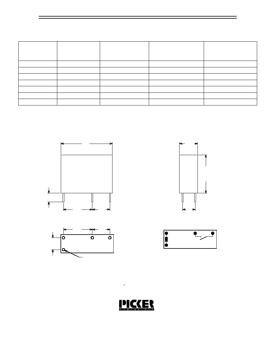
Tolerances + .010 unless otherwise noted
Notes:
Dimensions in Inches (millimeters)
Side View
End View
COIL DATA
Coil Voltage
5
6
12
18
24
Resistance
ohms + 10%
Must Operate
Voltage Max.
(VDC)
Must Release
Voltage Min.
(VDC)
Continuous
Voltage Max.
(VDC)
45
125
180
720
1620
2880
3.75
4.5
9.00
13.5
18.0
0.5
0.6
1.2
1.8
2.4
5.5
6.6
13.2
19.8
26.4
_
Note: Custom coil voltages within the ranges shown are available on special order.
3
2.25
0.3
3.3
9
405
6.75
0.9
9.9
Wiring Diagram
Drawings are 2X actual size
.283
(7.2)
(15.3)
.602
(20.5)
.807
(3.4)
.134
(7.0)
.275
(1.2)
.047 Dia. 4 Places
Hole Pattern
Relays previously tested or used above 10mA at 6VDC or higher
are not recommended for subsequent use in low level applications
(11.5)
.453
(4.7)
.185
(4.7)
.185
(7.0)
.275
(11.5)
.453